1
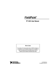
fpoint cd.qxd
11/13/00
1:23 PM
Page 1
FP-1600 FieldPoint Quick Start Guide
What You Need to Get Set Up
· Network Module
· Mounting Hardware (DIN rail
or panel mount accessory)
· Terminal Base(s)
· I/O Module(s)
1
· Power Supply
· FieldPoint Software CD
· Accessories: Ethernet cable,
screwdriver
Install the Network Module
DIN Rail Mount
A. Unlock rail clip.
Panel Mount
A. Unlock rail clip.
1
fpoint cd.qxd
11/13/00
1:23 PM
DIN Rail Mount
NOTE: Do not use spliced DIN
rails. Use only a single DIN rail.
Page 2
Panel Mount
B. Snap panel mount accessory
(which you can order separately)
onto module.
B. Hook lip on back of module onto top
of DIN rail, press down, and snap
into place.
C. Lock rail clip.
C. Slide module into position and lock
rail clip.
2
D. Use template that came with your
accessory to drill pilot holes and
mount module onto
panel using
accessory.
fpoint cd.qxd
2
11/13/00
1:23 PM
Page 3
Install the Terminal Base(s)
CAUTION: Terminal bases must be connected to the network module
before applying power to the module. Do not connect or disconnect
terminal bases while power is applied to the network module.
DIN Rail Mount
A. Unlock rail clip.
Panel Mount
A. Use template that came with your
accessory to drill pilot holes.
B. Connect terminal base to network
module connector, being careful not
to bend any connector pins.
B. Press base onto rail.
C. Fasten terminal base to panel.
3
fpoint cd.qxd
11/13/00
1:23 PM
DIN Rail Mount
C. Slide into position and lock the rail
clip. Be careful not to bend any pins.
Page 4
Panel Mount
D. Repeat for each terminal base, up to
nine for each network module in
most cases. You can use one or two
extender cables (which you can order
separately) if your FieldPoint bank is
too long for your available space.
E. Place protective cover on last base.
D. Repeat for each terminal base, up
to nine for each network module in
most cases. You can use one or
two extender cables (which you can
order separately) if your FieldPoint
bank is too long for your available
space.
E. Place protective cover on last base,
and install rail locks at each end.
4
fpoint cd.qxd
3
11/13/00
1:23 PM
Page 5
Install the I/O Module(s)
It does not matter where you install each I/O module, except for
these types of situations:
· If you plan to cascade power between any I/O modules using the
V and C terminals, those modules should be grouped together.
· For more accurate measurements, you might want to locate any
thermocouple modules away from heat sources, including network
modules or relay modules, unless you are mounting them on an FP-TB-3.
A. Align slots on module with guide rails on
base, and press onto base until terminal
base’s latch locks the module in place.
B. Repeat for each I/O module.
4
Connect the Network Cables
Connect the FP-1600 to an Ethernet network by connecting the RJ-45
Ethernet port of the FP-1600 to an Ethernet hub using a standard Category 5
Ethernet cable.
Straight-Through
UTP Cable
Straight-Through
UTP Cable
5
fpoint cd.qxd
11/13/00
1:23 PM
Page 6
Optionally, you can connect an FP-1600 directly to a computer using an
Ethernet crossover cable.
Cross-Over Cable
Do not use a cable longer than 100 m. If you are using a 100 Mbps Ethernet,
National Instruments recommends using a Category 5 shielded twisted-pair
Ethernet. If you need to build your own cable, refer to the FP-1600 User
Manual for cabling details.
5
Wire Power to Your FieldPoint System
A. Connect 11-30 VDC power supply leads to V and C terminals of the
network module. If you want to verify that your power supply is sufficient
for your modules and devices, refer to your FieldPoint hardware
documents for instructions on calculating power requirements.
B. Connect power to the FieldPoint modules that require external power for
outputs (output modules, counter modules, PWM, PG, QUAD). Refer to
the I/O module’s operating instructions for power requirement details.
You can power a module by connecting the V and C inputs on its terminal
base to a separate power supply, connecting the V and C outputs of a
neighboring terminal base or network module, or using a combination of
both methods. If you want to power field I/O devices from a terminal
base, supply power to the terminal base, and then connect the terminal
base V and C output terminals to the field device.
6
fpoint cd.qxd
11/13/00
1:23 PM
Page 7
CAUTION: Cascading power from neighboring bases or network modules
defeats isolation between cascaded modules.
Separate Power Supply
(Recommended)
No External
Power Required
Cascaded Power
(Reduces Isolation)
FP-1600
Power Supply
FP-AI-100
FP-AO-200
FP-RLY-420
FP-TC-120
Power Supply
15 16 V
Shades of gray indicate
different voltage potentials.
31 32 C
V 1 2 3
C 17 18
CAUTION: Cascading
power defeats isolation.
7
fpoint cd.qxd
6
11/13/00
1:23 PM
Page 8
Connect to Field Devices
Use each I/O module’s operating instructions, or the diagram under its
removable label, to help you connect your field devices.
FP-AI-110
8 Channel, 16-Bit Analog Input Module
Highlights
FP-AI-110
To Power
Supply
Overview
h.
-Bit
16
t
pu
g In A
alo
0m
An
,2
,V
mV
8-C
1
0
11
_1
MP
TE MP_23
TE MP_
E
T
-AI-
FP
0
17
4
Loop-Powered
Sensor
6
7
1
2
FP-AI-110
READY
POWER
3
CH0
CH1
CH2
CH3
CH4
CH5
CH6
CH7
VIN
1
3
5
7
9
11
13
15
8-Ch. 16-Bit Analog Input
I IN
2
4
6
8
10
12
14
16
2
15
32
5
VSUP COM
18
17
20
19
21
22
23
24
26
25
28
27
29
30
31
32
V
CURRENT
SOURCE
VSUP
POWERED
SOURCE
VIN
I Sensor
Channel 0
Self-Powered
Floating Sensor
VSensor
Channel 7
VOUT
I IN
+
-
COM
C
VOLTAGE
SOURCE
NOTE: Either the self-powered
sensor or power supply should be
floating (not tied to earth ground).
8
fpoint cd.qxd
7
11/13/00
1:23 PM
Page 9
Power Up Your FieldPoint System
CAUTION: Terminal bases must be connected to the FP-1600 before
power is applied to the FP-1600.
Plug in each power supply to
your FieldPoint bank. You should
see all except the STATUS and
PROCESS LEDs flash once, and
the POWER LED come on and
stay on. After a few seconds, the
POWER and READY LEDs should
be lit on each I/O module. If this
is not the case, refer to your
FP-1600 user manual for
troubleshooting instructions.
POWER and READY LEDs Stay Lit
The READY LEDs will not light until an IP address is assigned. Likewise, the
STATUS LED will stay lit until an IP address is assigned.
After the hardware is installed, you should verify communication, configure
the modules, configure your power-up states and watchdog settings. If you
are using National Instruments FieldPoint software for these tasks, continue
to the following section.
9
fpoint cd.qxd
8
11/13/00
1:24 PM
Page 10
Install the FieldPoint Software
A. Close all other applications. If you
plan to install National Instruments
development software such as
Lookout, LabVIEW, or Measurement
Studio, install them before you
install the FieldPoint software.
B. Insert the FieldPoint software CD and follow the onscreen instructions.
9
Verify the Installation
A. Select Start»Programs»National Instruments FieldPoint»FieldPoint
Explorer.
B. Right-click on the FieldPoint icon and select Add a comm resource to this
server.
10
fpoint cd.qxd
11/13/00
1:24 PM
Page 11
C. In the Comm Resource
Configuration dialog box, select
Ethernet as the Type.
D. Click Browse, select the
FP-1600, and click the Device
Properties button.
11
fpoint cd.qxd
11/13/00
1:24 PM
Page 12
E. In the FP-1600 Properties box, enter
values for the IP address, Subnet
mask, and Time server IP. You might
also want to enter a comment to help
you identify the FP-1600 module.
• IP address is the address of the
FP-1600 on the network.
• Subnet mask is the mask that is
applied to the IP address that the
device uses to find other devices on
the Ethernet network (255.255.255.0
is the most common).
• Time server IP is the address of the
host computer that the FP-1600 will synchronize its clock to. The
computer must have the Lookout Time Synch service (installed with
Lookout 4.x or FieldPoint 2.x).
F Click on Apply, then OK twice to return to the Comm Resource
Configuration dialog box.
G. Click on Find Devices.
H. Expand the +FP Res item on the left side of the Explorer window to see
the devices found on the network.
12
fpoint cd.qxd
11/13/00
1:24 PM
Page 13
If your modules are not
listed, check the cable and
connections and make sure the
modules are all powered on. If
you still have problems, refer
to your FP-1600 user manual
for troubleshooting
information.
I. Select an input module and
click on the start monitoring button
to view live data.
J. Select an output channel and click on the write button
outputs.
to change
K. Select File»Save.
13
fpoint cd.qxd
11/13/00
1:24 PM
Page 14
10 Configure I/O Modules
A. Right-click on the device name in FieldPoint Explorer and select Edit this
Device from the pop-up menu.
B. Click on the Channel Configuration button to bring up the Channel
Configuration dialog box.
C. Select the type of
channel to show,
then select the
channel(s) that
you want to
change. To select
more than one
channel, uncheck
the One channel
at a time box.
NOTE: Configuration options are module-dependent. The options
listed here might not be available for your particular module. Refer to
your I/O module operating instructions for details on configuration
options.
14
fpoint cd.qxd
11/13/00
1:24 PM
Page 15
D. Set the range and output values of the selected channel(s).
E. Set the attributes for the selected channel(s) by selecting the attribute and
entering the desired value.
F. Send commands to the selected channel(s) by choosing a command and
value and clicking on Send.
G. Repeat this procedure for each channel you want to configure.
H. Click on the OK button when you are finished, or click on the Apply
button to save the changes and continue to configure channels. When
you click on OK or Apply, the changes are immediately sent to the device.
I. Select File»Save when you are done.
15
fpoint cd.qxd
11/13/00
1:24 PM
11 Where to Go from Here
Page 16
After you get your hardware up and running, you might want to implement
features such as power-up defaults or network watchdog settings. Refer to
your FP-1600 user manual or online help for information about features,
configuration, application development, and troubleshooting.
16
fpoint cd.qxd
11/13/00
1:24 PM
Page 17
FP-1600 Specifications
Network interface . . . . . . . . . . . . . . . . . . . . 10BaseT and 100BaseTX Ethernet
Compatibility. . . . . . . . . . . . . . . . . . . . . . . . IEEE 802.3
Communications rate . . . . . . . . . . . . . . . . . 10 Mbps, 100 Mbps, autonegotiated
Cabling distance . . . . . . . . . . . . . . . . . . . . . 100 m
Power supply range . . . . . . . . . . . . . . . . . . 11 to 30 VDC
Power consumption . . . . . . . . . . . . . . . . . . 7 W + 1.15 * (I/O module power requirements)
Maximum terminal bases per bank . . . . . . . 9
Maximum number of banks. . . . . . . . . . . . . determined by network topology
Operating temperature. . . . . . . . . . . . . . . . . –20 to +55 °C
Storage temperature . . . . . . . . . . . . . . . . . . –55 to +85 °C
Relative humidity . . . . . . . . . . . . . . . . . . . . 5% to 90% non-condensing
Weight . . . . . . . . . . . . . . . . . . . . . . . . . . . . 280 g (9.9 oz.)
Compliance
Electrical safety . . . . . . . . . . . . . . . . . . . . . . designed to meet IEC 1010
EMI emissions/immunity . . . . . . . . . . . . . . . CISPR 11
CE Mark Compliance
This product meets applicable EU directive(s) as follows:
EMC directive
Immunity . . . . . . . . . . . . . . . . . . . . . . EN 50082–1:1994
Emissions . . . . . . . . . . . . . . . . . . . . . EN 55011:1991 Group I Class A at 10 meters
17
fpoint cd.qxd
11/13/00
1:24 PM
Page 18
Mechanical Dimensions
Dimensions are given in inches [millimeters].
4.22 [107.19]
4.31
[109.5]
3.60 [91.44]
18
fpoint cd.qxd
11/13/00
1:24 PM
Page 20
United States 512 795-8248
Australia 03 9879 5166, Austria 0662 45 79 90 0, Belgium 02 757 00 20,
Brazil 011 284 5011, Canada (Calgary) 403 274 9391,
Canada (Ontario) 905 785 0085, Canada (Québec) 514 694 8521,
China 0755 3904939, Denmark 45 76 26 00, Finland 09 725 725 11,
France 01 48 14 24 24, Germany 089 741 31 30, Greece 30 1 42 96 427,
Hong Kong 2645 3186, India 91805275406, Israel 03 6120092, Italy 02 413091,
Japan 03 5472 2970, Korea 02 596 7456, Mexico (D.F.) 5 280 7625,
Mexico (Monterrey) 8 357 7695, Netherlands 0348 433466, Norway 32 27 73 00,
Singapore 2265886, Spain (Barcelona) 93 582 0251, Spain (Madrid) 91 640
0085, Sweden 08 587 895 00, Switzerland 056 200 51 51, Taiwan 02 2377 1200,
United Kingdom 01635 523545
© Copyright 1999, 2000 National Instruments Corporation.
All rights reserved. CVI™, FieldPoint™, LabVIEW™, Lookout™, Measurement Studio™, and
ni.com™ are trademarks of National Instruments Corporation. Product and company names
mentioned herein are trademarks or trade names of their respective companies.