1
User’s
Manual
Model UT150L
Communication Functions
IM 05C01E22-10E
IM 05C01E22-10E
3rd Edition
Introduction
This instruction manual describes the communication functions of the UT150L controller and contains
information on how to create communication programs.
Read the manual carefully to understand the communication functions of the UT150L.
The UT150L controller has the following communication protocols.
1) PC link communication protocol
2) MODBUS communication protocol
Note that the UT150L controller cannot communicate with a host device with a communication
protocol other than these.
■ Intended Readers
This manual is intended for people familiar with the functions of the UT150L Controller and control
engineers and personnel in charge of maintaining instrumentation and control equipment.
You are required to understand as a background knowledge the communication specifications of
higher-level devices, in regard to their communication hardware, language used for creating communication programs, and so on.
■ Related Documents
The following instruction manuals all relate to the communication functions.
Read them as necessary. The codes enclosed in parentheses are the document numbers.
• Model UT150L Limit Controller
Explains the basic operation of the UT150L controller.
Supplied with the UT150L Limit Controller.
FD No. IM 05C01E22-10E
3rd Edition: Jun. 2004 (YK)
AllRights Reserved. Copyright © 2000. Yokogawa Electric Corporation
IM 05C01E22-10E
(IM 05C01E22-01E)
i
Documentation Conventions
■ Symbols
The following symbols are used in this manual.
●Symbols Used in the Main Text
CAUTION
Draws attention to information that is essential for understanding the operation and/or features of the
product.
NOTE
Gives additional information to complement the present topic and/or describe terms specific to this
document.
See Also
Gives reference locations for further information on the topic.
■ Description of Displays
(1) Some of the representations of product displays shown in this manual may be exaggerated,
simplified, or partially omitted for reasons of convenience when explaining them.
(2) Figures and illustrations representing the controller’s displays may differ from the real displays in
regard to the position and/or indicated characters (upper-case or lower-case, for example), to the
extent that they do not impair a correct understanding of the functions and the proper operation and
monitoring of the system.
ii
IM 05C01E22-10E
Notices
■ Regarding This Instruction Manual
(1) This manual should be passed on to the end user. Keep at least one extra copy of the manual in a
safe place.
(2) Read this manual carefully to gain a thorough understanding of how to operate this product before
you start using it.
(3) This manual is intended to describe the functions of this product. Yokogawa Electric Corporation
(hereinafter simply referred to as Yokogawa) does not guarantee that these functions are suited to
the particular purpose of the user.
(4) Under absolutely no circumstance may the contents of this manual, in part or in whole, be transcribed or copied without permission.
(5) The contents of this manual are subject to change without prior notice.
(6) Every effort has been made to ensure accuracy in the preparation of this manual. Should any
errors or omissions come to your attention however, please contact your nearest Yokogawa
representative or our sales office.
■ Regarding Protection, Safety, and Prohibition Against Unauthorized Modification
(1) In order to protect the product and the system controlled by it against damage and ensure its safe
use, make certain that all of the instructions and precautions relating to safety contained in this
document are strictly adhered to. Yokogawa does not guarantee safety if products are not handled
according to these instructions.
(2) The following safety symbols are used on the product and/or in this manual.
●Symbols Used on the Product and in This Manual
CAUTION
This symbol on the product indicates that the operator must refer to an explanation in the instruction
manual in order to avoid the risk of injury or death of personnel or damage to the instrument. The
manual describes how the operator should exercise special care to avoid electrical shock or other
dangers that may result in injury or loss of life.
Protective Grounding Terminal
This symbol indicates that the terminal must be connected to ground prior to operating the equipment.
Functional Grounding Terminal
This symbol indicates that the terminal must be connected to ground prior to operating the equipment.
IM 05C01E22-10E
iii
■ Force Majeure
(1) Yokogawa does not make any warranties regarding the product except those mentioned in the
WARRANTY that is provided separately.
(2) Yokogawa assumes no liability to any party for any loss or damage, direct or indirect, caused by
the use or any unpredictable defect of the product.
(3) Be sure to use the spare parts approved by Yokogawa when replacing parts or consumables.
(4) Modification of the product is strictly prohibited.
(5) Use this software with one specified computer only. You must purchase another copy of the
software for use on each additional computer.
(6) Copying this software for purposes other than backup is strictly prohibited.
(7) Store the floppy disk(s) (original medium or media) containing this software in a secure place.
(8) Reverse engineering such as the disassembly or decompilation of software is strictly prohibited.
(9) No portion of the software supplied by Yokogawa may be transferred, exchanged, leased or sublet
for use by any third party without the prior permission of Yokogawa.
iv
IM 05C01E22-10E
Contents
Introduction ........................................................................................................................... i
Documentation Conventions ............................................................................................... ii
Notices ................................................................................................................................. iii
Chapter 1. Setup ............................................................................................................. 1-1
1.1
1.2
Setup Procedure .............................................................................................. 1-1
Notes on Setting Parameters ........................................................................... 1-2
Chapter 2. Communication Specifications ................................................................... 2-1
2.1
RS-485 Communication Specifications .......................................................... 2-1
Chapter 3. PC Link Communication ............................................................................ 3-1
3.1
Overview ......................................................................................................... 3-1
3.1.1 Configuration of Command ..................................................................... 3-2
3.1.2 Configuration of Response ...................................................................... 3-3
3.2 Communication with Host Device .................................................................. 3-4
3.2.1 List of Commands ................................................................................... 3-5
3.2.2 Specifying Broadcast ............................................................................... 3-6
3.2.3 Commands ............................................................................................... 3-7
3.2.4 Response Error Codes ........................................................................... 3-20
3.3 Example of BASIC Program for Send and Receive .................................... 3-21
Chapter 4. MODBUS Communication ......................................................................... 4-1
4.1
Overview ......................................................................................................... 4-1
4.1.1 Configuration of Message ....................................................................... 4-2
4.2 Communication with Host Device .................................................................. 4-3
4.2.1 List of Function Codes ............................................................................ 4-3
4.2.2 Specifying Broadcast ............................................................................... 4-4
4.2.3 Function Codes ........................................................................................ 4-5
4.2.4 Response Error Codes ............................................................................. 4-9
Chapter 5. Functions and Usage of D Registers.......................................................... 5-1
5.1
5.2
Overview of D Registers ................................................................................. 5-1
Interpretation of Lists of D Registers
(D Register Map Tables) ................................................................................. 5-1
5.3 Classification of D Registers .......................................................................... 5-2
5.4 Register Map Table ......................................................................................... 5-3
5.4.1 D Register Contents ................................................................................. 5-4
Chapter 6. Functions and Usage of I Relays ............................................................... 6-1
6.1
IM 05C01E22-10E
Status I Relays ................................................................................................. 6-1
v
Appendix
Table of ASCII Codes (Alphanumeric Codes) ................................... App. 1
Revision Record .................................................................................................................... i
vi
IM 05C01E22-10E
Chapter 1 Setup
1.
Setup
This chapter describes the setup procedure required to be able to use the communication functions (PC
link, and MODBUS) and the communication parameters of the UT150L.
1.1
Setup Procedure
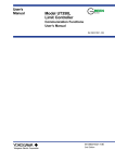
Set up the communication functions on the UT150L as follows:
Set up the communication function parameters of the UT150L. (See Section 1.2.)
Connect a higher-level device and a UT150L. (See the connection diagram below.)
Create communication programs for the higher-level device to perform communication.
* Communication programs should be created referring to the documentation of each higher-level device.
● For UT150L connection
PC, PLC, or graphic panel
UT150L
RSB(+)
B(+)
RSA(-)
A(-)
3
4
UT150L
RSB(+)
RSA(-)
3
4
Terminating
resistor
220Ω
1/4 W
SG
Shield
SG
5
SG
Terminating
resistor
220Ω
1/4 W
5
Grounding resistance of no greater than
100Ω
Grounding resistance of no greater than
100Ω
IM 05C01E22-10E
1-1
1.2
Notes on Setting Parameters
This section describes the setting parameters for using the communication functions and their setting
ranges.
NOTE
The details of UT150L communication functions need to be the same as those of the communication
functions of the host devices to be connected. Check the communication parameters of the host device
first, then set up those of the UT150L.
Table 1-1 Parameters to be Set for Communication Functions
Parameter Name
Protocol selection
PSL
Default
Setting Range
Symbol
PC link communication
0: without sum check
1: with sum check
MODBUS communication
3: ASCII mode
4: RTU mode
0
Address
ADR
1 to 99
1
Baud rate
BPS
0: 2400, 1: 4800, 2: 9600
2: 9600
Parity
PRI
0: none, 1: even, 2: odd
1: EVN
Stop bit
STP
1, 2
1
Data length
DLN
7, 8 (Note 1)
8
Note 1: When “3: ASCII mode” is selected for MODBUS communication in protocol selection, the data length is fixed to “7.”
When “4: RTU mode” is selected, it is fixed to “8.”
● Protocol-by-Protocol Default Parameter Settings
Parameter
Communication Protocol
PC-link communication without sum check
PSL
BPS
PRI
STP
DLN
0
9600
EVN
1
8
PC-link communication with sum check
1
9600
EVN
1
8
MODBUS communication (ASCII mode)
3
9600
EVN
1
7
MODBUS communication (RTU mode)
4
9600
EVN
1
8
Note: Circled numbers denote fixed values.
● Protocol selection (PSL)
Set the same communication protocol as that of the host device to be connected. The UT150L has PC
link communication, and MODBUS communication functions.
1-2
IM 05C01E22-10E
Chapter 1 Setup
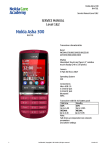
● Address number (ADR)
Set the address number of the UT150L itself. An address number of 1 to 99 may be assigned in any
order. There is however one limitation — the number of UT150L to be connected to a single communication port is limited to 31.
Example of connecting four UT150L to a host device by setting address numbers of 1, 50, 10, and 20
Personal computer
Maximum overall cable length of 1200 m for a maximum of 31 substations
ADR=1
ADR=50 ADR=10
ADR=20
● Baud rate (BPS)
Set the same communication rate as that of the host device to be connected. (Otherwise, proper
communication cannot be achieved.) The unit of the communication rate is bps (bits per second).
● Parity (PRI)
Set the handling of parity to be carried out when data is sent or received. Set the same parity state as
that of the host device to be connected.
● Stop bit (STP)
Set the same stop bit as that of the host device to be connected.
● Data length (DLN)
Set the same data length as that of the host device to be connected. (When MODBUS communication
(PSL: 3 or 4) is chosen in protocol selection, the data length is fixed.)
IM 05C01E22-10E
1-3
1-4
IM 05C01E22-10E
Chapter 2 Communication Specifications
2.
Communication Specifications
The RS-485 communication interface has the PC link communication, and the MODBUS communication.
Table 2-1 UT150L Communication Protocol
Communication Hardware
2-wire RS-485 communication system
Terminal
Terminal numbers: 3-5
Communication Protocol
Specifications
PC link communication without sum check
PC link communication with sum check
MODBUS communication (ASCII mode)
MODBUS communication (RTU mode)
Maximum Baud Rate
9600 bps
Table 2-2 Types of Devices to be Connected
Device to be Connected
PC
2.1
Communication Protocol
Example of Connected Devices
PC link communication
General-purpose PCs
MODBUS communication
General-purpose PCs
RS-485 Communication Specifications
Table 2-3 RS-485 Communication Interface
Specifications
Item
Standard
EIA RS-485 compliant
Maximum number of devices to be connected
31
Communication system
2-wire, half duplex
Synchronization
Asynchronous (start-stop)
Communication protocol
No-protocol
Maximum communication distance
1200 m
Baud rate
2400, 4800, 9600
IM 05C01E22-10E
2-1
2-2
IM 05C01E22-10E
Chapter 3 PC Link Communication
3.
3.1
PC Link Communication
Overview
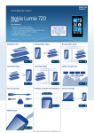
Personal computer
Maximum overall cable length of 1200 m for a maximum of 31 substations
Figure 3-1 Connection of Slaves in PC Link Communication
The use of PC link communication enables UT150L to communicate with a device such as a PC,
easily. In this communication, you can use such device to read/write data from/into D registers or read
data from I relays, both of which are internal registers of the UT150L.
Hereafter, PCs, are generally called “host devices.”
See Also
Chapters 5 and 6 for information on the D registers and I relays.
In the PC link communication, a host device identifies each UT150L with a communication address of
1 to 99. Some of commands to use let you to specify broadcast that requires no address numbers. For
more information on broadcast specification, see subsection 3.2.2.
IM 05C01E22-10E
3-1
3.1.1
Configuration of Command
Commands sent from a host device to UT150L, consist of the following elements.
Number of
Bytes
1
2
2
1
3
Variable length
2
1
1
STX
Address
number
(ADR)
CPU
number
01
Time to
wait for
response
0
Command
Data corresponding
to command
Checksum
ETX
CR
(1)
(2)
(3)
(4)
(5)
(6)
(7)
(8)
(9)
Element
(1) STX (Start of Text)
This control code indicates the start of a command. The character code is CHR$(2).
(2) Address Number (01 to 99)
Address numbers are used by the host device to identify UT150L at the communication destination.
(They are identification numbers specific to the UT150L.)
(3) CPU Number
This number is fixed to 01.
(4) Time to Wait for Response
This is fixed to 0.
(5) Command (See subsection 3.2.1, List of Commands)
Specify a command to be issued from the host device.
(6) Data Corresponding to Command
Specify an internal register (D register or I relay), number of data pieces, UT150L parameter value,
and others.
(7) Checksum
This converts the ASCII codes of texts between the character next to STX and the character immediately before the checksum into hexadecimal values and adds them byte by byte. It then fetches the
single lowermost byte of the added results as the checksum.
This column is only required for PC link communication with checksum. PC link communication
without checksum does not require this 2-byte space of ASCII code.
(8) ETX (End of Text)
This control code indicates the end of a command string. The character code is CHR$(3).
(9) CR (Carriage Return)
This control code indicates the end of a command. The character code is CHR$(13).
NOTE
The control codes STX, ETX, and CR are essential for commands when you create a communication
program for PC link communication. Omission of any of them or incorrect order of them results in
communication failure.
3-2
IM 05C01E22-10E
Chapter 3 PC Link Communication
● Data Form of Commands
The table below shows the data forms of commands for D registers and I relays.
Table 3-1 Data Forms of Commands for D Registers and I Relays
Type of Data
Contents of Data
Specified Form
PV high and low limits, target setpoints, and others
Measuring range (EU) data
Numeric data not including the decimal point
Bias, deviation alarms, and other
Measuring range width (EUS) data
Numeric data not including the decimal point
Proportional bands, upper and lower limits of
output, and others
% data (0.0 to 100.0%)
0 to 1000
Various modes, alarm types, and others
Seconds, absolute values, and data
without unit
Absolute values not including the
decimal point
● Command Format for Communication
Example: When setting a target setpoint “50.0” to a UT150L, the host device sends the value “500” as
command data without the decimal point (this is true for both setting 5.00 or 500).
Data to be send from the host device: hexadecimal value of 500 (01F4)
Command data: 01F4
Response data from UT150L: 01F4
UT150L side
Target setpoint: 50.0
The position of the decimal point for “500” is determined by the DP (position of decimal point) parameter of the UT150L.
*
3.1.2
Configuration of Response
Responses from UT150L with respect to a command sent from the host device consists of the elements shown below, which differ depending on the condition of communication; normal or failure.
1) Normal Communication
When communication is complete normally, UT150L return a character string “OK” and when the
read commands, return read-out data.
Number of
Bytes
1
2
2
2
Variable length
2
1
1
STX
Address
number
(ADR)
CPU
number
01
OK
Parameter data
Checksum
ETX
CR
Element
2) In the Event of Failure
If communication is complete abnormally, UT150L return a character string “ER” and error code
(EC1 and EC2). (See subsection 3.2.4, Response Error Codes.)
• No response is made in case of an error in address number specification or CPU number specification.
• If a UT150L cannot receive ETX in a command, response may not be made.
* As a measure against those, provide a timeout process in the communication functions of the host
device or in communication programs.
Number of
Bytes
Element
IM 05C01E22-10E
1
2
2
2
2
2
3
2
1
1
STX
Address
number
(ADR)
CPU
number
01
ER
EC1
EC2
Command
Checksum
ETX
CR
3-3
3.2
Communication with Host Device
In PC link communication, when specifying D registers or I relays, the internal registers of UT150L,
you can use their numbers as is. The specifications of the number of each internal register are:
• D registers: D**** (****: numeric value)
• I relays:
I**** (****: numeric value)
Host devices to be connected to UT150L are those capable of handling the PC link communication
protocol.
As an example of communication program, Section 3.3 shows an example of BASIC program created
using Microsoft Quick BASIC.
3-4
IM 05C01E22-10E
Chapter 3 PC Link Communication
3.2.1
List of Commands
The following shows the lists of commands available in PC link communication. The details of them
are explained in the description of each command.
(1) Bit-basis Access Commands Dedicated to I Relays
Command
Description
Number of Bits to be Handled
BRD
Bit-basis read
1 to 48 bits
BWR
Bit-basis write
1 to 32 bits
BRR
Bit-basis, random read
1 to 16 bits
BRW
Bit-basis, random write
1 to 16 bits
BRS
Specifies I relays to be monitored on a bit-by-bit basis.
1 to 16 bits
BRM
Bit-basis monitoring
—
(2) Word-basis Access Commands
Command
Description
Number of Bits to be Handled
WRD
Word-basis read
1 to 32 words
WWR
Word-basis write
1 to 32 words
WRR
Word-basis, random read
1 to 16 words
WRW
Word-basis, random write
1 to 16 words
WRS
Specified internal registers to be monitored on a word basis
1 to 16 words
WRM
Word-basis monitoring
—
(3) Information Command
Command
INF
IM 05C01E22-10E
Description
Reads model, presence/absence of option, and revision.
Number of Devices to be Handled
1
3-5
3.2.2
Specifying Broadcast
The personal computer sends data to all of the substations at one time.
Note: The substations do not give any response.
Host controller (master station)
Maximum overall cable length of 1200 m for a maximum of 31 substations
Figure 3-2 Specifying Broadcast
The broadcast function enables all of the connected UT150L or other devices to receive a command.
Specifying an address number in Table 3-3 for the address number column in a command enables the
host device to write data from/into the internal registers of all UT150L or other devices.
For UT150L, internal registers (D registers and I relays) are assigned with numbers for management.
(See chapters 5 and 6 for details.) For the internal registers of other models, see the documentation of
the relevant model.
Table 3-2 Address Numbers
ADR
BG
3-6
Applicable Devices
UT150L and UT100 Series
IM 05C01E22-10E
Chapter 3 PC Link Communication
3.2.3
Commands
BRD
Reads I relays on a bit-by-bit basis.
● Function
Reads a sequence of contiguous ON/OFF statuses by the specified number of bits starting at a specified I relay number.
• The number of bits to be read at a time is 1 to 48.
• For the format of response in the event of failure, see subsection 3.1.2.
• The command shown below includes the checksum function. When performing communication
without checksum, do not include the 2-byte checksum command element in the command.
● Command/Response (for normal operation)
Number of
Bytes
Command
element
Number of
Bytes
Response
element
1
2
2
1
3
5
1
3
2
1
1
STX
Address
number
(ADR)
CPU
number
01
0
BRD
I relay
number
Comma
or space
Number
of bits
(n)
Checksum
ETX
CR
1
2
2
2
1
1
1
…
1
2
1
1
STX
Address
number
(ADR)
CPU
number
01
OK
d1
d2
d3
…
dn
Checksum
ETX
CR
The response is “0” when the status is OFF or “1” when ON.
dn: read data to the extent of the specified number of bits (n = 1 to 48)
dn = 0 (OFF)
dn = 1 (ON)
● Example: Reading the status of alarm 1 of the UT150L with address number 01
The following command reads the status of alarm 1 (I0001) at address number 01.
[Command]
STX$+ “01010BRDI0001, 00191” +ETX$+CR$
The following response is returned with respect to the above command. (Alarm 1 is ON.)
[Response]
STX$+ “0101OK18D” +ETX$+CR$
Alarm has been ON since 1 was returned.
IM 05C01E22-10E
3-7
BWR
Writes data into I relays on a bit-by-bit basis.
● Function
Writes ON/OFF data into a sequence of contiguous I relays at intervals of the specified number of bits
and starting at a specified I relay number.
• The number of bits to be written at a time is 1 to 32.
• For the format of response in the event of failure, see subsection 3.1.2.
• The command shown below includes a checksum function. When performing communication
without checksum, do not include the 2-byte checksum command element in the command.
● Command/Response (for normal operation)
Number of
Bytes
Command
element
1
2
2
1
3
5
1
3
1
1
1
STX
Address
number
(ADR)
CPU
number
01
0
BWR
I relay
number
Comma
or space
Number
of bits
(n)
Comma
or space
d1
d2
Command (continued)
…
1
2
1
1
…
dn
Checksum
ETX
CR
Write information is “0” when it is OFF or “1” when it is ON.
dn: write data to the extent of the specified number of bits (n = 1 to 32)
dn = 0 (OFF)
dn = 1 (ON)
Number of
Bytes
Response
element
1
2
2
2
2
1
1
STX
Address
number
(ADR)
CPU
number
01
OK
Checksum
ETX
CR
● Example: Setting the user-defined flag of UT150L with address number 01 to ON.
The following command writes ON into the user-defined flag (I0018) at address number 01.
[Command]
STX$+ “01010BWRI0018, 001, 1AC” +ETX$+CR$
Note: The user-defined flag is a flag the user can read/write without restraint. For areas available to
the user, see Chapter 6, Functions and Applications of I Relays.
“OK” is returned as the response to the above command.
[Response]
3-8
STX$+ “0101OK5C” +ETX$+CR$
IM 05C01E22-10E
Chapter 3 PC Link Communication
BRR
Reads I relays on a bit-by-bit basis in a random order.
● Function
Reads the ON/OFF statuses of I relays at intervals of the specified number of bits in a random order.
• The number of bits to be read at a time is 1 to 16.
• For the format of response in the event of failure, see subsection 3.1.2.
• The command shown below includes a checksum function. When performing communication
without a checksum, do not include the 2-byte checksum command element in the command.
● Command/Response (for normal operation)
Number of
Bytes
Command
element
1
2
2
1
3
2
5
1
5
1
STX
Address
number
(ADR)
CPU
number
01
0
BRR
Number
of bits
(n)
I relay
number
1
Comma
or space
I relay
number
2
Comma
or space
Command (continued)
…
5
2
1
1
…
I relay
number
n
Checksum
ETX
CR
Number of
Bytes
Response
element
1
2
2
2
1
1
…
1
2
1
1
STX
Address
number
(ADR)
CPU
number
01
OK
d1
d2
…
dn
Checksum
ETX
CR
The response is “0” when the status is OFF or “1” when ON.
dn: read data to the extent of the specified number of bits (n = 1 to 16)
dn = 0 (OFF)
dn = 1 (ON)
● Example: Reading the statuses of alarms 1 and 2 of the UT150L with address number 05
The following command reads the statuses of alarm 1 (I0001) and alarm 2 (I0002) at address number 05.
[Command]
STX$+ “05010BRR04I0001, I00027F” +ETX$+CR$
With respect to the above command, the ON and OFF responses are returned for alarms 1 and 2
respectively.
[Response]
STX$+ “0501OK10C1” +ETX$+CR$
Alarm 1 has been ON.
IM 05C01E22-10E
3-9
BRW
Writes data into I relays on a bit-by-bit basis in a random order.
● Function
Writes ON/OFF statuses into I relays at intervals of the specified number of bits on a per-I relay basis
and in random order.
• The number of bits to be written at a time is 1 to 16.
• For the format of response in the event of failure, see subsection 3.1.2.
• The command shown below includes the checksum function. When performing communication
without a checksum, do not include the 2-byte checksum command element in the command.
● Command/Response (for normal operation)
Number of
Bytes
Command
element
1
2
2
1
3
2
5
1
1
1
5
STX
Address
number
(ADR)
CPU
number
01
0
BRW
Number
of bits
(n)
I relay
number
1
Comma
or space
d1
Comma
or space
I relay
number
2
Command (continued)
1
1
1
…
5
1
1
2
1
1
Comma
or space
d2
Comma
or space
…
I relay
number
n
Comma
or space
dn
Checksum
ETX
CR
Write information is “0” when it is OFF or “1” when it is ON.
dn: write data to the extent of the specified number of bits (n = 1 to 16)
dn = 0 (OFF)
dn = 1 (ON)
Number of
Bytes
Response
element
1
2
2
2
2
1
1
STX
Address
number
(ADR)
CPU
number
01
OK
Checksum
ETX
CR
● Example: Setting four user-defined flags of the UT150L with address number 05 to ON, OFF,
OFF, and ON.
The following command sets the four user-defined flags (I0025, I0026, I0027, and I0028) at address
number 05 to ON, OFF, OFF, and ON respectively.
[Command]
STX$+ “05010BRW04I0025, 1, I0026, 0, I0027, 0, I0028, 181” +ETX$+CR$
Note: The user-defined flags (I relays) are flags that the user can freely read/write. For areas available
to the user, see Chapter 6, Functions and Applications of I Relays.
“OK” is returned as the response to the above command.
[Response]
3-10
STX$+ “0501OK60” +ETX$+CR$
IM 05C01E22-10E
Chapter 3 PC Link Communication
BRS
Specifies I relays to be monitored on a bit-by-bit basis.
● Function
Specifies the numbers of I relays to be monitored on a bit-by-bit basis. Note that this command simply
specifies I relays. Actual monitoring is performed by the BRM command after the I relay numbers are
specified.
When the volume of data is large and you wish to increase the communication rate, it is effective to
use a combination of the BRS and BRM commands rather than the BRD command.
• The number of registers to be specified at a time is 1 to 16.
• For the format of response in the event of failure, see subsection 3.1.2.
• The command shown below includes the checksum function. When performing communication
without a checksum, do not include the 2-byte checksum command element in the command.
● Command/Response (for normal operation)
Number of
Bytes
Command
element
1
2
2
1
3
2
5
1
3
1
STX
Address
number
(ADR)
CPU
number
01
0
BRS
Number
of bits
(n)
I relay
number
1
Comma
or space
I relay
number
2
Comma
or space
Command (continued)
…
5
2
1
1
…
I relay
number
n
Checksum
ETX
CR
Number of
Bytes
Response
element
1
2
2
2
2
1
1
STX
Address
number
(ADR)
CPU
number
01
OK
Checksum
ETX
CR
● Example: Monitoring the PV burnout status of the UT150L with address number 05
The following command monitors the PV burnout status (I0007) at address number 05.
(This command is used for simply specifying registers.)
[Command]
STX$+ “05010BRS01I00074D” +ETX$+CR$
“OK” is returned as the response to the above command.
[Response]
IM 05C01E22-10E
STX$+ “0501OK60” +ETX$+CR$
3-11
BRM
Monitors I relays on a bit-by-bit basis.
● Function
Reads the ON/OFF statuses of I relays that have been specified in advance by the BRS command.
• Before executing this command, the BRS command must always be executed to specify which I
relays are to be monitored. If no relay has been specified, error code 06 is generated. This error also
occurs if the power supply is turned off.
• For the format of response in the event of failure, see subsection 3.1.2.
• The command shown below includes the checksum function. When performing communication
without the checksum, do not include the 2-byte checksum command element in the command.
● Command/Response (for normal operation)
Number of
Bytes
Command
element
Number of
Bytes
Response
element
1
2
2
1
3
2
1
1
STX
Address
number
(ADR)
CPU
number
01
0
BRM
Checksum
ETX
CR
1
2
2
2
1
1
1
…
1
2
1
1
STX
Address
number
(ADR)
CPU
number
01
OK
d1
d2
d3
…
dn
Checksum
ETX
CR
The response is “0” when the status is OFF or “1” when ON.
dn: read data to the extent of the number of bits specified by the BRS command (n = 1 to 16)
dn = 0 (OFF)
dn = 1 (ON)
● Example: Monitoring the PV burnout status of the UT150L with address number 05
The following command monitors the PV burnout status (I0007) at address number 05.
(This command reads the statuses of the I relays specified by the BRS command.)
[Command]
STX$+ “05010BRMD7” +ETX$+CR$
The ON/OFF status of the I relay is returned as the response to the above command.
[Response]
STX$+ “0501OK191” +ETX$+CR$
I relay has been ON.
3-12
IM 05C01E22-10E
Chapter 3 PC Link Communication
WRD
Reads D registers and I relays on a word-by-word basis.
● Function
Reads a sequence of contiguous register information on a word-by-word basis, by the specified
number of words, and starting at the specified register number.
• The number of words to be read at a time is 1 to 32.
• For the format of response in the event of failure, see subsection 3.1.2.
• The command shown below includes the checksum function. When performing communication
without the checksum, do not include the 2-byte checksum command element in the command.
● Command/Response (for normal operation)
Number of
Bytes
Command
element
Number of
Bytes
Response
element
1
2
2
1
3
5
1
2
2
1
1
STX
Address
number
(ADR)
CPU
number
01
0
WRD
Register
number
Comma
or space
Number
of words
(n)
Checksum
ETX
CR
1
2
2
2
4
4
…
4
2
1
1
STX
Address
number
(ADR)
CPU
number
01
OK
dddd1
dddd2
…
ddddn
Checksum
ETX
CR
The response is returned in a 4-digit character string (0000 to FFFF) in a hexadecimal pattern.
Read data of the specified number of words
ddddn = character string in a hexadecimal pattern
n = 1 to 32
● Example: Reading a measured input value of the UT150L with address number 03
The following command reads the measured input value (D0002) at address number 03.
[Command]
STX$+ “03010WRDD0002, 0174” +ETX$+CR$
The measured input value 200 (00C8 (HEX)) is returned as the response to the above command.
[Response]
IM 05C01E22-10E
STX$+ “0301OK00C839” +ETX$+CR$
3-13
WWR
Writes data into D registers and I relays on a word-by-word basis.
● Function
Writes information into a sequence of contiguous registers on a word-by-word basis, by the specified
number of words, and starting at the specified register number.
• The number of words to be written at a time is 1 to 32.
• For the format of response in the event of failure, see subsection 3.1.2.
• The command shown below includes the checksum function. When performing communication
without the checksum, do not include the 2-byte checksum command element in the command.
● Command/Response (for normal operation)
Number of
Bytes
Command
element
1
2
2
1
3
5
1
2
1
4
STX
Address
number
(ADR)
CPU
number
01
0
WWR
Register
number
Comma
or space
Number
of words
(n)
Comma
or space
dddd1
Command (continued)
4
…
4
2
1
1
dddd2
…
ddddn
Checksum
ETX
CR
Write information is specified in a 4-digit character string (0000 to FFFF) in a hexadecimal pattern.
Write data of the specified number of words
ddddn = character string in a hexadecimal pattern
n = 1 to 32
Number of
Bytes
Response
element
1
2
2
2
2
1
1
STX
Address
number
(ADR)
CPU
number
01
OK
Checksum
ETX
CR
● Example: Writing “200” into target setpoint of UT150L with address number 03.
The following command writes data 200 (00C8 (HEX)) into the target setpoint 1 (D0120) at address
number 03.
[Command]
STX$+ “03010WWRD0120, 01, 00C88F” +ETX$+CR$
“OK” is returned as the response to the above command.
[Response]
3-14
STX$+ “0301OK5E” +ETX$+CR$
IM 05C01E22-10E
Chapter 3 PC Link Communication
WRR
Reads D registers and I relays on a word-by-word basis in random order.
● Function
Reads the statuses of registers on a word-by-word basis, by the specified number of words and in a
random order.
• The number of words to be read at a time is 1 to 16.
• For the format of response in the event of failure, see subsection 3.1.2.
• The command shown below includes the checksum function. When performing communication
without the checksum, do not include the 2-byte checksum command element in the command.
● Command/Response (for normal operation)
Number of
Bytes
Command
element
1
2
2
1
3
2
5
1
5
1
STX
Address
number
(ADR)
CPU
number
01
0
WRR
Number
of words
(n)
Register
number
1
Comma
or space
Register
number
2
Comma
or space
Command (continued)
…
5
2
1
1
…
Register
number
(n)
Checksum
ETX
CR
Number of
Bytes
Response
element
1
2
2
2
4
4
…
4
2
1
1
STX
Address
number
(ADR)
CPU
number
01
OK
dddd1
dddd2
…
ddddn
Checksum
ETX
CR
The response is returned in a 4-digit character string (0000 to FFFF) in a hexadecimal pattern.
ddddn = character string in a hexadecimal pattern (n = 1 to 16)
● Example: Reading the measured input and output values of the UT150L with address number 10.
The following command reads the measured input value (D0002) and the target setpoint (D0003) at
address number 10.
[Command]
STX$+ “10010WRR02D0002, D000388” +ETX$+CR$
The measured input value 200 (00C8 (HEX)) and output value 50 (0032 (HEX)) are returned as
the response to the above command.
[Response]
IM 05C01E22-10E
STX$+ “1001OK00C80032FC” +ETX$+CR$
3-15
WRW
Writes data into D registers and I relays on a word-by-word basis in random order.
● Function
Writes register information specified for each register into registers of the specified number of words
in a random order.
• The number of words to be written at a time is 1 to 16.
• For the format of response in the event of failure, see subsection 3.1.2.
• The command shown below includes the checksum function. When performing communication
without the checksum, do not include the 2-byte checksum command element in the command.
● Command/Response (for normal operation)
Number of
Bytes
Command
element
1
2
2
1
3
2
5
1
4
1
STX
Address
number
(ADR)
CPU
number
01
0
WRW
Number
of words
(n)
Register
number
1
Comma
or space
dddd1
Comma
or space
Command (continued)
5
1
4
…
5
1
4
2
1
1
Register
number
2
Comma
or space
dddd2
…
Register
number
n
Comma
or space
ddddn
Checksum
ETX
CR
Write information is specified in a 4-digit character string (0000 to FFFF) in a hexadecimal pattern.
Repetition of register numbers and write information by the specified number of words
ddddn = character string in a hexadecimal pattern
n = 1 to 16
Number of
Bytes
Response
element
1
2
2
2
2
1
1
STX
Address
number
(ADR)
CPU
number
01
OK
Checksum
ETX
CR
● Example: Writing “20.0” into target setpoint 1 of UT150L with address number 10 and “15.0” into
the alarm-1 setpoint.
The following command writes
“20.0” into target setpoint 1 (D0120) and “15.0” into the alarm-1 setpoint (D0101) at address number 10.
[Command]
STX$+ “10010WRW02D0120, 00C8, D0101, 009694” +ETX$+CR$
Target setpoint: 200
Alarm setpoint: 150
“OK” is returned as the response to the above command.
[Response]
3-16
STX$+ “1001OK5C” +ETX$+CR$
IM 05C01E22-10E
Chapter 3 PC Link Communication
WRS
Specifies the D registers and I relays to be monitored on a word-by-word basis.
● Function
Specifies the numbers of the registers to be monitored on a word-by-word basis. Note that this
command simply specifies the registers. Actual monitoring is performed by the WRM command after
the register numbers are specified by this command.
If the volume of data is large and you wish to increase the communication rate, it is useful to use a
combination of the WRS and WRM commands rather than the WRD command. If the power supply is
turned off, the register numbers specified will be erased.
• The number of words to be specified at a time is 1 to 16.
• For the format of response in the event of failure, see subsection 3.1.2.
• The command shown below includes the checksum function. When performing communication
without the checksum, do not include the 2-byte checksum command element in the command.
● Command/Response (for normal operation)
Number of
Bytes
Command
element
1
2
2
1
3
2
5
1
5
1
STX
Address
number
(ADR)
CPU
number
01
0
WRS
Number
of words
(n)
Register
number
1
Comma
or space
Register
number
2
Comma
or space
Command (continued)
…
5
2
1
1
…
Register
number
n
Checksum
ETX
CR
Number of
Bytes
Response
element
1
2
2
2
2
1
1
STX
Address
number
(ADR)
CPU
number
01
OK
Checksum
ETX
CR
● Example: Monitoring the measured input value of UT150L with address number 01
The following command monitors the measured input value (D0002) at address number 01.
(This command simply specifies the registers.)
[Command]
STX$+ “01010WRS01D000255” +ETX$+CR$
CPU number: 01
D register number: D0002
“OK” is returned as the response to the above command.
[Response]
IM 05C01E22-10E
STX$+ “0101OK5C” +ETX$+CR$
3-17
WRM
Monitors the D register and I relays on a word-by-word basis.
● Function
Reads register information that has been specified in advance by the WRS command.
• Before executing this command, the WRS command must always be executed to specify which
registers are to be monitored. If no register has been specified, error code 06 is generated. This error
also occurs if the power supply is turned off.
• For the format of response in the event of failure, see subsection 3.1.2.
• The command shown below includes the checksum function. When performing communication
without the checksum, do not include the 2-byte checksum command element in the command.
● Command/Response (for normal operation)
Number of
Bytes
Command
element
Number of
Bytes
Response
element
1
2
2
1
3
2
1
1
STX
Address
number
(ADR)
CPU
number
01
0
WRM
Checksum
ETX
CR
1
2
2
2
4
4
…
4
2
1
1
STX
Address
number
(ADR)
CPU
number
01
OK
dddd1
dddd2
…
ddddn
Checksum
ETX
CR
The response is returned in a 4-digit character string (0000 to FFFF) in a hexadecimal pattern.
Read data of the number of words specified by the WRS command
ddddn = character string in a hexadecimal pattern
n = 1 to 16
● Example: Monitoring the measured input value of UT150L with address number 01
The following command monitors the measured input value (D0002) at address number 01.
(This command reads the statuses of the registers specified by the WRS command.)
[Command]
STX$+ “01010WRME8” +ETX$+CR$
CPU number: 01
The measured input value 200 (00C8 (HEX)) is returned as the response to the above command.
[Response]
STX$+ “0101OK00C837” +ETX$+CR$
Measured input value: 200
3-18
IM 05C01E22-10E
Chapter 3 PC Link Communication
INF
Reads the model, presence or absence of options, and revisions.
● Function
Returns the model number of UT150L, whether any options are included, and the version number and
revision number are read.
• For the format of response in the event of failure, see subsection 3.1.2.
● Command/Response (for normal operation)
Number of
Bytes
Command
element
Number of
Bytes
Response
element
1
2
2
1
3
1
2
1
1
STX
Address
number
(ADR)
CPU
number
01
0
INF
6
Checksum
ETX
CR
1
2
2
2
8
7
1
4
4
STX
Address
number
(ADR)
CPU
number
01
OK
UT150L ■ ■
(Note 1)
Version
Revision
(Note 2)
Space
Readout start
register for
special device
Number of
readout registers
for special device
Response (continued)
4
4
2
1
1
Write start
register for
special device
Number of write
registers for
special device
Checksum
ETX
CR
Note: Model and option of UT150L
UT150L
01: Two alarms
04: Communication function
10: One contact input
20: 4-to-20 mA DC retransmission output
Note: Version number and revision number
V0L. R01
Revision number
Space
IM 05C01E22-10E
Version number
3-19
3.2.4
Response Error Codes
See Also
Subsection 3.1.2, Configuration of Response, for the structure of the response in the event of error.
The error codes (EC1) and detailed error codes (EC2) of response are as follows.
Table 3-3 List of Error Codes EC1
Error Code
Causes
Meaning
02
Command error
• No command exists.
• Command not executable
03
Internal register
specification error
• No register number exists.
• If a bit register (I relay) is used on a word-by-word basis, its specification is
not correct.
04
Out of setpoint range
• A character other than 0 or 1 has been used for the bit setting.
• A value other than 0000 to FFFF has been specified in the word specification.
• The position of a start for a data load, save, or other command, is out of the
address range.
05
Out of data number range
• The specification of the number of bits or words is out of the range of use.
• The number of data specified and the number of parameters for registers, etc.
are not consistent.
06
Monitor error
• An attempt was made to execute monitoring without specifying the monitor
(BRS or WRS).
08
Parameter error
• An illegal parameter is set.
42
Sum error
• The sum does not match the expected value.
43
Internal buffer overflow
• A data value greater than specified is received.
44
Character reception time-out
• The end-of-data or end-of-text character is not received.
Table 3-4 List of Detailed Error Codes EC2
Error Code
(EC1)
Meaning
03
Device specification error
04
Out of setpoint range
05
Out of data number range
Detailed Error Code (EC2)
Parameter number where error occurred (HEX)
This is the number of a parameter in sequence that first resulted in error when
counted from the leading parameter.
Example:
Error in device name specification
STX 01010BRW 05 I0017, 1, I0018, 0, A00502
Parameter numbers 1
2
3
4
5
6
In this case, EC1 = 03 and EC2 = 06
08
Parameter error
An illegal paraeter is set.
For error codes other than those noted as EC1, there is no EC2 meaning.
3-20
IM 05C01E22-10E
Chapter 3 PC Link Communication
3.3
Example of BASIC Program for Send and Receive
This section shows an example of a command sending and response receiving program created with
Microsoft Quick BASIC*2 for PC/AT*1 (or compatible machines).
The communication conditions of the UT150L and those of the PC (e.g., communication rate) must
agree with each other. Set the communication rate (baud rate) of the PC using the SWITCH command
of MS-DOS*3. For how to use the SWITCH command, refer to the User’s Reference Manual of MSDOS. Moreover, set the parity, character bit length, stop bit length, and so on using the OPEN
statement.
*1 PC/AT is a product of IBM Corporation.
*2 Microsoft Quick BASIC is a registered trademark of Microsoft Corporation.
*3 MS-DOS is a registered trademark of Microsoft Corporation.
IM 05C01E22-10E
3-21
1000
1010
1020
1030
1040
1050
1060
1070
1080
1090
1100
1110
1120
1130
1140
1150
1160
1170
1180
1190
1200
1210
1220
1230
1240
1250
1260
1270
1280
1290
1300
1310
1320
1330
1340
1350
1360
1370
1380
1390
1400
1410
1420
1430
1440
3-22
Example of the Program Created Using Microsoft Quick BASIC Version 7.1
(Reads the values in three D registers from register 0002.)
‘ === Main routine ===
‘ Define
STX$=CHR$(2)
ETX$=CHR$(3)
‘ Define
CR$=CHR$(13)
‘ Define
RCVCHR$= “”
‘ Initialize receive character string
fRCVEND=0
‘ Initialize flag
fTIMEOUT=0
‘ Initialize flag
‘
SEND$=STX$+”01010WRDD0002,03"+ETX$
‘ Create character string for send
‘
OPEN “COM1:9600,N,8,1,ASC” FOR RANDOM AS #1 ‘ Open a port
ON COM(1) GOSUB receivechr
‘ Specify interruption processing during
receiving
ON TIME(5) GOSUB timeout
‘ Specify interruption processing at timeout
‘
PRINT #1,SEND$
‘ Send
COM(1) ON
‘ Permit interruption during receive
TIMER ON
‘ Start timer
‘
DO
‘ Wait for receive end or timeout
LOOP WHILE fRCVEND=0 AND fTIMEOUT=0 ‘
‘
TIMER OFF
‘ Stop timer
COM(1) OFF
‘ Prohibit interruption during receiving
CLOSE #1
‘ Close the port
‘
PRINT “>”+SEND$
‘ Display sent character string on screen
PRINT “<”+RCVCHR$
‘ Display received character string on
screen
END
‘ END
‘
‘ === Subroutine ===
receivechr:
‘ Interruption processing during receiving
CHR1$=INPUT\(1,#1)
‘ Fetch characters from receive buffer
one by one
IF CHR1$=CR$ THEN
‘ If received character string is “CR,”
IF RCVCHR$=SEND$ THEN
‘ If received character string is the same
served command,
RCVCHR$= “”
’ Initialize receive character string. (Echo
Back Processing)
fRCVEND=0
‘ receiving flag remains initialized at 0.
ELSE
‘ If received character string is different
from served command,
fRCVEND=1
‘ receiving end flag is set.
END IF
‘
ELSE
‘ If it is a character other than CR,
fRCVEND=0
‘ receiving end flag remains initialized at 0.
RCVCHR$=RCVCHR$+CHR1$
‘ Create received character string
END IF
‘
RETURN
‘
IM 05C01E22-10E
Chapter 3 PC Link Communication
1450
1460
1470
timeout:
fTIMEOUT=1
RCVCHR$=”Time out !
(5 sec)”+CR$
‘ Timeout processing
‘ Set timeout flag
‘ Character string for display on screen
“Time out! (5 sec)”
1480 RETURN
↑
* The line numbers are not required. (They are simply provided for checking the number of program
steps.)
IM 05C01E22-10E
3-23
3-24
IM 05C01E22-10E
Chapter 4 MODBUS Communication
4.
4.1
MODBUS Communication
Overview
Personal computer
Maximum overall cable length of 1200 m for a maximum of 31 substations
Figure 4-1 Connection of Slaves in MODBUS Communication
Use of the MODBUS communication enables UT150L to communicate with a wide variety of devices
such as PCs. In this communication, you use such device to read/write data from/into D registers,
(internal registers) of the UT150L.
Hereafter, PCs are generally called “host devices.”
See Also
Chapter 5 for information on the D registers.
For the MODBUS communication of the UT150L, we provide the ASCII mode (ASCII system) and
RTU mode (binary system) for the communication mode.
Table 4-1 ASCII and RTU Modes
Item
ASCII Mode
RTU Mode
Number of data bits
7 bits (ASCII)
8 bits (binary)
Message start mark
: (colon)
Not necessary
Message end mark
CR + LF
Not necessary
Length of message (Note 1) 2N + 1
N
Data time intervals
1 second or less
24 bit time or less (Note 2)
Error detection
Longitudinal redundancy check: LRC
Cyclic redundancy check: CRC-16
Note 1: When the length of a message in the RTU mode, it is assumed to be “N.”
Note 2: When the communication rate is 9600 bps, 1 9600 24 sec or less.
In the MODBUS communication, a higher-level device identifies each UT150L with a communication
address of 1 to 99. Some of the commands used let you specify broadcast that requires no address
numbers. For more information on broadcast specifications, see subsection 4.2.2.
IM 05C01E22-10E
4-1
4.1.1
Configuration of Message
Messages sent from a higher-level device to UT150L, consists of the following elements.
Element
Number of bytes in RTU mode
Number of bytes in ASCII mode
Start of
Message
Mark
Address
Number
(ADR)
Function
Code
Data
Error
Check
End of
Message
Mark
None
1
1
2n
2
None
1
2
2
4n
2
2
(1)
(2)
(3)
(4)
(5)
(6)
(1) Start of Message Mark
This mark indicates the start of a message. Note that only ASCII mode requires the colon.
(2) Address Number (1 to 99)
Address numbers are used by host devices to identify the UT150L at the communication destination.
(These numbers are identification numbers specific to individual UT150L.)
(3) Function Code (See subsection 3.2.1, List of Function Codes)
The function code specifies a command (function code) from the higher-level device.
(4) Data
This element specifies D register numbers, the number of D registers, parameter values, and so on in
accordance with the function code.
(5) Error Check
In RTU mode
Carried out by the cyclic redundancy check (CRC-16) system.
In ASCII mode
Carried out by the longitudinal redundancy check (LRC) system.
(6) End of Message Mark
This mark indicates the end of a message.
Note that only ASCII mode requires CR + LF
● Message format for communication
Example: When setting the target setpoint “50.0” to a UT150L, the higher-level device sends message
data (01F4) into a value of “500” converted into hexadecimals not including the decimal point (thus,
this is true for sending both 5.00 or 500).
Message data in the higher-level device: hexadecimal value of 500 (01F4)
Message data: 01F4
Response data from UT150L: 01F4
UT150L side
Target setpoint: 50.0
* The position of the decimal point for “500” is determined by the DP (position of decimal point) parameter of the UT150L.
4-2
IM 05C01E22-10E
Chapter 4 MODBUS Communication
4.2
Communication with Host Device
The specification of D registers for a message using commercially available SCADA or the like and
specification of D registers for a message in customer-created communication programs are different
from simple specification of D register numbers. Thus, care should be taken.
(1) When using commercially available SCADA or the like, specify the D register numbers by
changing them into reference numbers. D register numbers whose “D” leading character is replaced
with “4,” are treated as reference numbers. (When using a DDE server or others, specify these
reference numbers.)
(2) For communication programs created by the customer, specify registers using the hexadecimal
numbers of values that are obtained by subtracting “40001” from the reference numbers. (Thus,
hexadecimal numbers are those to be specified.)
Example: To specify target setpoint “D0120”:
(1) For a message using commercially available SCADA or the like, specify reference number
“40120.”
(2) For a message in a customer-created communication program, specify the hexadecimal number, or
0077, of a value (0119) obtained by subtracting 40001 from the reference number.
4.2.1
List of Function Codes
Function codes are command words used by the higher-level device to obtain the D register information of UT150L.
Table 4-2 List of Function Codes
Code Number
Function
Description
03
Reads data from multiple D registers.
Capable of reading data from a maximum of 32 successive D
registers between D0001 and D0421.
06
Writes data into D register.
Capable of writing data to one D register between D0101 and
D0421.
08
Performs loop back test.
See subsection 4.2.3, “Function Codes.
16
Writes data into multiple D registers.
Capable of writing data into a maximum of 32 successive D
registers between D0101 and D0421.
• A write using the function code is not possible for read-only or disabled D registers.
• Broadcast can be specified for function codes 06 and 16 only.
IM 05C01E22-10E
4-3
4.2.2
Specifying Broadcast
The personal computer sends data to all of the substations at one time.
Note: The substations do not give any response.
Host controller (master station)
Maximum overall cable length of 1200 m for a maximum of 31 substations
Figure 4-2 Specifying Broadcast
Broadcast is a feature in which all connected UT150L can receive the command concerned. Specifying
the number in Table 4-3 at the location of the address number in a message enables the higher-level
device to write data into the D registers of all UT150L.
Table 4-3 Broadcast Specification Number
4-4
Number to be Specified in ADR
Applicable Devices
00
UT150L
IM 05C01E22-10E
Chapter 4 MODBUS Communication
4.2.3
Function Codes
03
Reads data from multiple D registers.
● Function
This function code reads the contents of successive D registers by the specified number of them
starting at a specified D register number.
• The maximum number of D registers to be read at a time is 32.
• For the format of responses in the event of failure, see subsection 4.2.4.
● Message (for normal operation)
Element
Number of bytes in
RTU mode
Number of bytes in
ASCII mode
Start of
Message
Mark (:)
Address
Number (ADR)
Function Code
(03)
D-Register Start
Number
(Upper Digit)
D-Register Start
Number
(Lower Digit)
None
1
1
1
1
1
2
2
2
2
Message (continued)
Number of
D Registers
(Upper Digit)
Number of
D Registers
(Lower Digit)
Error
Check
End of Message
Mark
(CR + LF)
1
1
2
None
2
2
2
2
● Response (for normal operation)
Element
Start of
Message
Mark (:)
Address
Number
(ADR)
Function
Code
(03)
Byte
Count
Contents of
D-Register
(Upper Digit)
Contents of
D-Register
(Lower Digit)
…
None
1
1
1
1
1
…
1
2
2
2
2
2
…
Number of bytes in
RTU mode
Number of bytes in
ASCII mode
Response (continued)
Contents of
D Registers
(Upper Digit)
Contents of
D Registers
(Lower Digit)
Error
Check
End of Message
Mark
(CR + LF)
1
1
2
None
2
2
2
2
● Example: Reading the statuses of alarms 1 and 2 from the UT150L with address number 17.
The following message reads four successive D registers starting at alarm 1 (D0101) and address
number 17 in the ASCII mode.
[Message]
[ : ]11030064000286[CR][LF]
Start of message mark
“11”: address number 17, “03”: function code 03, “0064”: D register address 0101, “0002”: number
of D registers 2, and “86”: error check
* Numbers in quotation marks are hexadecimal.
The following response is returned with respect to the above message.
[Response]
[ : ]110304005A000A84[CR][LF]
Setting of alarm1, alarm2
“04”: byte count, “005A”: alarm 1 setpoint 90, “000A”: alarm 2 setting 10
IM 05C01E22-10E
4-5
16
Writes data into D registers.
● Function
This function code writes data into successive D registers by the number of specified D registers from
a specified D register number.
• The maximum number of D registers into which data is written at a time is 32.
• For the format of response in the event of failure, see subsection 4.2.4.
• Lets you specify broadcast (by setting “00” to the address number).
● Message (for normal operation)
Element
Number of bytes in
RTU mode
Number of bytes in
ASCII mode
Start of
Message
Mark (:)
Address
Number
(ADR)
Function Code
(10)
D-Register Start
Number
(Upper Digit)
D-Register Start
Number
(Lower Digit)
None
1
1
1
1
1
2
2
2
2
Massage (continued)
Number of
D Registers
(Upper Digit)
Number of
D Registers
(Lower Digit)
Byte
Count
Data
(Upper Digit)
Data
(Lower Digit)
…
Error
Check
End of Message
Mark
(CR + LF)
1
1
1
1
1
…
2
None
2
2
2
2
2
…
2
2
● Response (for normal operation)
Element
Number of bytes in
RTU mode
Number of bytes in
ASCII mode
Start of
Message
Mark (:)
Address
Number
(ADR)
Function Code
(10)
D-Register Start
Number
(Upper Digit)
D-Register Start
Number
(Lower Digit)
None
1
1
1
1
1
2
2
2
2
Response (continued)
Number of D
Registers
(Upper Digit)
Number of D
Registers
(Lower Digit)
Error
Check
End of Message
Mark
(CR + LF)
1
1
2
None
2
2
2
2
● Example: Setting a alarm-1 setpoint of 80, and a alarm-2 setpoint of 70 to UT150L with address
number 02.
The following message writes values 80, and 70 in this order in the ASCII mode, starting at the
proportional band (D0101) of address number 02.
[Message]
[ : ]0210006400020400500046EE[CR][LF]
Start of message mark
“02”: address number 02, “10”: function code 16, “0064”: starts register address 0101, “0002”:
number of D registers 2, “04”: byte count, “0050”: alarm-1 setpoint 80, “0046”: alarm-2 setpoint 70,
and “EE”: error check
* Numbers in quotation marks are hexadecimal.
The following response is returned with respect to the above message.
[Response]
[ : ]02100064000288[CR][LF]
Number of D registers: 2
4-6
IM 05C01E22-10E
Chapter 4 MODBUS Communication
06
Writes data into D register.
● Function
This function code writes data into a specified D register number.
• The maximum number of D registers into which data is written at a time is 1.
• For the format of response in the event of failure, see subsection 4.2.4.
• Lets you specify broadcast (by setting “00” to the address number).
● Message (for normal operation)
Element
Number of bytes in
RTU mode
Number of bytes in
ASCII mode
Start of
Message
Mark (:)
Address
Number
(ADR)
Function Code
(06)
D-Register
Number
(Upper Digit)
D-Register
Number
(Lower Digit)
None
1
1
1
1
1
2
2
2
2
Message (continued)
Write Data
(Upper Digit)
Write Data
(Lower Digit)
Error
Check
End of Message
Mark
(CR + LF)
1
1
2
None
2
2
2
2
● Response (for normal operation)
Element
Number of bytes in
RTU mode
Number of bytes in
ASCII mode
Start of
Message
Mark (:)
Address
Number
(ADR)
Function Code
(06)
D-Register
Number
(Upper Digit)
D-Register
Number
(Lower Digit)
None
1
1
1
1
1
2
2
2
2
Response (continued)
Write Data
(Upper Digit)
Write Data
(Lower Digit)
Error
Check
End of Message
Mark
(CR + LF)
1
1
2
None
2
2
2
2
● Example: Setting 70.0 to the target setpoint of UT150L with address number 01.
The following message writes “700” to the target setpoint (D0120) at address number 01 in the ASCII
mode.
[Message]
[ : ]0106007702BCC4[CR][LF]
Start of message mark
“01”: address number 01, “06”: function code 06, “0077”: D-register address 0120, “02BC”: target
setpoint 70.0, and “C4”: error check
* Numbers in quotation marks are hexadecimal.
The response of the same contents is returned with respect to the above message.
[Response]
[ : ]0106007702BCC4[CR][LF]
Target setpoint: 70.0
IM 05C01E22-10E
4-7
08
Performs a loop back test.
● Function
This function code is used to check connection for communication.
• For the format of response in the event of failure, see subsection 4.2.4.
• The specification of a D register number (marked with an asterisk below) for a loop back test is
“00” (fixed).
• Any value can be selected for send data.
● Message (for normal operation)
Element
Number of bytes in
RTU mode
Number of bytes in
ASCII mode
Start of
Message
Mark (:)
Address
Number
(ADR)
Function Code
(08)
00
(Upper Digit)
00
(Lower Digit)
None
1
1
1
1
1
2
2
2
2
Message (continued)
Send Data
(Upper Digit)
Send Data
(Lower Digit)
Error
Check
End of Message
Mark
(CR + LF)
1
1
2
None
2
2
2
2
● Response (for normal operation)
Element
Number of bytes in
RTU mode
Number of bytes in
ASCII mode
Start of
Message
Mark (:)
Address
Number
(ADR)
Function Code
(08)
00
(Upper Digit)
00
(Lower Digit)
None
1
1
1
1
1
2
2
2
2
Response (continued)
Send Data
(Upper Digit)
Send Data
(Lower Digit)
Error
Check
End of Message
Mark
(CR + LF)
1
1
2
None
2
2
2
2
● Example: Sending data 1234h to UT150L with address number 05 to check connection for
communication.
The following message sends “1234” (hexadecimal) to address number 05 in the ASCII mode.
[Message]
[ : ]050800001234AD[CR][LF]
Start of message mark
“05”: address number 05, “08”: function code 08, “0000”: fixed, “1234”: send data, and “AD”: error
check
* Numbers in quotation marks are hexadecimal.
When connection for communication is normal, the following response is returned with respect to the
above message.
[Response]
[ : ]050800001234AD[CR][LF]
“1234”: send data
4-8
IM 05C01E22-10E
Chapter 4 MODBUS Communication
4.2.4
Response Error Codes
● Message Format in the Event of Error
If there is any inconsistency other then communication errors in a message, UT150L does nothing, but
returns the following message.
Element
Address Number
(ADR)
Function Code*
Error Code
Error Check
1
1
1
2
2
2
2
2
Number of bytes in
RTU mode
Number of bytes in
ASCII mode
* The function code contains a function code (hexadecimal number) + 80 (hexadecimal number).
● Error Codes in Response
Table 4-4 List of Error Codes
Error Code
Description
Meaning
01
Function code error
No function code exists.
02
D-register address error
Address out of the range has been specified.
03
D-register count error
Number of D registers has been specified, being out of the range.
● Even when a message is sent, no response returns if:
• Retransmission error (overrun, framing, parity, LRC, or CRC-16 error) was detected.
• Address in an instructed message is incorrect.
• Interval between data composing a message was 1 second or more.
• Broadcast is specified (address number: 00).
* As a measure against those, provide a timeout process in the communication functions of a higherlevel device or in communication programs.
IM 05C01E22-10E
4-9
4-10
IM 05C01E22-10E
Chapter 5 Functions and Usage of D Registers
5.
5.1
Functions and Usage of D Registers
Overview of D Registers
This section explains the functions and usage of D registers.
The D registers store the parameter data, flag data and process data that are handled by UT150L
controller. By connecting UT150L controller to host devices capable of PC link communication, or
MODBUS communication, you can readily use these internal data items by reading from or writing to
the D registers.
Using the D registers, you can perform:
• Centralized control using host devices
• Data exchange by reading/writing using host devices
5.2
Interpretation of Lists of D Registers
(D Register Map Tables)
This section explains how to read the “D Register Map” tables in this chapter. In the example shown
below, the number in the leftmost column denotes (1) D-register number. The five-digit number in the
column on the immediate right of the leftmost column represents (2) Reference number for MODBUS
communication. The number in the column third from left is (3) Register number (hexadecimal) for
the MODBUS communication program. Each register code name in the D Register Map tables
represents register name of specific process data item, operating parameter, setup parameter or other
data items. For details on the operating and setup parameters, see Model UT150L Limit Controller
instruction manual (IM 05C01E22-01E).
Name of D Register Map
D-Reg No.
Ref No.
H No.
Register name
D0001
40001
0000
STATUS
(1) D register number
R/W
*
(3) Hex number (for MODBUS communication)
R
Reading/writing via communication
(R: reading; W: writing)
(2) Reference number (for MODBUS communication)
An asterisk (*) indicates that the number of
writing actions is limited to 100,000 times.
IM 05C01E22-10E
5-1
5.3
Classification of D Registers
■ Classification of D Register Map Tables
The table below outlines how the D registers are classified by their numbers in the D Register Map tables.
Table 5-1 Classification of D Registers
Register No.
Description
Area and Data Categories
D0001 to 0010
Process data area
(Note 1)
D0401 to 0420
User area (Note 2),
represented by shaded
section in the table ( )
D0011 to 0100
D0121 to 0200
D0216 to 0300
D0307 to 0400
Must not be used.
D0101 to 0120
Operating parameters
area *1
D0201 to 0215
Setup parameters area
*1
Reference
PV, CSP and other values
Section
5.4
Used for communication with the
Host devices.
Section
5.4
Operating parameter
FL, BS etc.
Section
5.4
Setup parameter
AL, HY etc.
Section
5.4
Operating data
–
D0301 to 0306
Note 1: Data for process values, operating parameters and setup parameters are stored as the types (EU, EUS, % and ABS without
the decimal point) indicated in the "Operating Parameters" and the "Setup Parameters" of the UT150L Limit Controller instruction manual. The OFF and ON states are represented by 0 and 1, respectively. The D registers D0401 to 0420 are
read-only.
Note 2: The user area (register numbers D0401 to 0420) is reserved for 16-bit register data used in other software programs.
When working with host devices, do not write to or read from this area as usually done.
NOTE
No data may be written to or read from data storage areas with blank fields in the tables that follow.
If you attempt to do so, UT150L controller may fail to operate correctly.
5-2
IM 05C01E22-10E
Chapter 5 Functions and Usage of D Registers
5.4
Register Map Table
Area for Process Data
D-Reg No.
D0001
Ref No.
40001
H No.
0000
Register Name
STATUS
D0002
D0003
40002
40003
0001
0002
PV
CSP
R/W
R
R
R
D-Reg No.
D0216 to 0300
Ref No.
H No.
Register Name
R/W
D0301
D0302
40301
40302
012C
012B
IN
DP
*R/W
*R/W
D0004
D0303
40303
012E
RH
*R/W
D0005
D0006
D0304
D0305
40304
40305
012F
0130
RL
SPH
*R/W
*R/W
D0007
D0306
40306
0131
SPL
*R/W
D0008
D0009
D0313 to 0400
D0401
40009
0008
TIM
R
40401
0037
R/W
D0010
D0011 to 0100
40010
0009
MOD
R
D0402
D0403
40402
40403
0038
0039
R/W
R/W
D0101
40101
0064
A1
*R/W
D0404
40404
003A
R/W
D0102
D0103
40102
0065
A2
*R/W
D0405
D0406
40405
40406
003B
003C
R/W
R/W
D0104
D0105
D0407
D0408
40407
40408
003D
003E
R/W
R/W
D0106
D0409
40409
003F
R/W
D0107
D0108
D0410
D0411
40410
40411
0040
0041
R/W
R/W
D0109
D0110
D0111
D0112
D0412
D0413
D0414
D0415
40412
40413
40414
40415
0042
0043
0044
0045
R/W
R/W
R/W
R/W
D0416
D0417
D0418
D0419
40416
40417
40418
40419
0046
0047
0048
0049
R/W
R/W
R/W
R/W
D0420
40420
004A
R/W
D0113
D0114
D0115
D0116
D0117
D0118
D0119
D0120
D0121 to 0200
D0201
D0202
D0203
D0204
D0205
D0206
D0207
D0208
D0209
D0210
D0211
D0212
D0213
D0214
D0215
40111
006E
HYS
*R/W
40114
0071
SP1
*R/W
40116
0073
FL
*R/W
40117
40118
0074
0075
BS
LOC
*R/W
*R/W
40120
0077
CSP1
R/W
40203
40204
40205
40206
40207
40208
40209
40210
40211
40212
40213
40214
40215
00CA
00CB
00CC
00CD
00CE
00CF
00D0
00D1
00D2
00D3
00D4
00D5
00D6
AL1
AL2
HY1
HY2
DIS
HILO
OPSL
PSL
ADR
BPS
PRI
STP
DLN
*R/W
*R/W
*R/W
*R/W
*R/W
*R/W
*R/W
*R/W
*R/W
*R/W
*R/W
*R/W
*R/W
Shaded areas
indicate a user area (D-register numbers D0401 to D0420). These registers are not available if the host
devices.
An asterisk ( * ) indicates that the number of writing actions is limited to 100,000 times
IM 05C01E22-10E
5-3
5.4.1
D Register Contents
D registers are designed to indicate two or more events, such as errors and parameter data, using
combinations of bits within them. If any of the events shown in the following tables occurs, the
corresponding bit is set to 1. The bit remains set to 0 if the event has not occurred yet. Note that bits
in blank fields are not in use.
● D0001 Register - Bit Configuration of STATUS (Input Error)
Bit
Code
Event
0
1
2
3
4
5
6
7
8
9
10
11
12
13
14
15
ALM1.st
ALM2.st
0
0
PV+over.st
PV-over.st
BO.st
0
SYSTEM.E.st
CALB.E.st
PARA.E.st
0
ADERR.st
RJCERR.st
EEP.E.st
0
‘1’ if alarm 1 is on, or ‘0’ if off
‘1’ if alarm 2 is on, or ‘0’ if off
PV above the upper limit of scale
PV below the lower limit of scale
Burn-out error
Error in system data
Error in calibrated values
Error in operating parameters
Error in automatical calibration of valve position
Error in A/D Converter
RJC error in PV
Error in EEPROM
● D0002 Register - PV (Measured Input Value)
● D0003 Register - CSP (Currently used Target Setpoint)
● D0009 Register - TIM (Duration Time)
Example: The reading for one hours, 38 minutes and 57 seconds is given as 5.937 seconds.
● D0010 Register - MOD
Bit
Code
0
0
1
EXD. st
2
OUT. st
3 to 15
0
(Limit Control Status)
Event
0:Not extend, 1:Extend
0:Relay off/Lamp on, 1:Relay on/Lamp off
● D0101 and D0102 Registers - A1 and A2 (Alarm or Timer Setpoints)
If either “23” or “24” is set in the AL1 and AL2 registers, the value is used as the setpoint for the
timer in units of seconds. If a value other than “23” and “24” is set, it is used as the alarm setpoint.
● D120 Register-CSP1 (Target Setpoint for writing via Communication Only)
The CSP1 parameter is a target setpoint for use via communication only and is effective only if the
SP1 parameter is selected. Use this register when you want to change the target setpoint by means
of communication. Once you write a value into this register, the D0114 (SP1) register contains the
same value. Note that data in the D0120 register is not recorded when the power is turned off.
When the power is turned back on, the D0120 register contains the value previously written into the
D0114 (SP1) register.
5-4
IM 05C01E22-10E
Chapter 6 Functions and Usage of I Relays
6.
Functions and Usage of I Relays
This chapter explains the functions and usage of the I relays.
The I relays contain information on errors in UT150L controller, as well as the controller’s alarm
statuses. By connecting the UT150L controller to host devices (via PC communication link), you can
read these internal data items from the I relays to use for your own particular purpose. (Note that
most of the I relays have the same functions as the D registers.)
6.1
Status I Relays
The following table summarizes how the on-off status I relays are classified.
I Relay No.
Data Category
Description
Remarks
1 to 16, 50, 51
On-off
statuses
Error information (same as data in the D0001
register)
17 to 48
Read/Write
User area (Data can be written to or read from
the range of I relays)
Information stored in each group of these
I relays is represented by the four sets of
binary codes, from 0000 (0 in the
decimal system) to 1000 (8 in the
decimal system), which are formed by
each combination of four I relays. The
lowest-numbered I relay in each set
signifies the LSB of the four bits.
NOTE
The on-off status I relays numbered 1 to 16 store on-off status information. In normal operation, this
area can be accessed to read the on-off status.
When specifying an I relay number via communication, begin the number with an upper-case letter I.
For example, type I0014 to specify the RJCERR.st relay (I relay numbered 14).
No data may be written to or read from data storage areas with blank fields in the tables that follow.
If you attempt to do so, UT150L controller may fail to operate correctly.
Area of I Relays
No.
I Relay
I Relay
I Relay
I Relay
I Relay
I Relay
No.
No.
No.
No.
No.
Name Code
Name Code
Name Code
Name Code
Name Code
Name Code
1 ALM1.st
11 PARA.E.st
21 UR5
31 UR15
41 UR25
51 OUT
2 ALM2.st
12
22 UR6
32 UR16
42 UR26
52
3
13 ADERR.st
23 UR7
33 UR17
43 UR27
53
4
14 RJCERR.st
24 UR8
34 UR18
44 UR28
54
5 PV+over.st
15 EEP.E.st
25 UR9
35 UR19
45 UR29
55
6 PV-over.st
16
26 UR10
36 UR20
46 UR30
56
7 BO.st
17 UR1
27 UR11
37 UR21
47 UR31
8
18 UR2
28 UR12
38 UR22
48 UR32
9 SYSTEM.E.st
19 UR3
29 UR13
39 UR23
49
20 UR4
30 UR14
40 UR24
50 EXD
10 CALB.E.st
IM 05C01E22-10E
6-1
6-2
IM 05C01E22-10E
Appendix Table of ASCII Codes (Alphanumeric Codes)
Appendix
Table of ASCII Codes (Alphanumeric Codes)
In order to implement PC link communication, create a transmission/receiving program by referring to
the following table of ASCII codes.
0
0
0
0
b8
b7
b6
b5
0
0
0
1
0
0
1
0
0
0
1
1
0
1
0
0
0
1
0
1
0
1
1
0
0
1
1
1
b4
b3
b2
b1
0
1
2
3
4
5
6
7
0
0
0
0
0
NUL
DLE
SP
0
@
P
`
p
0
0
0
1
1
SOH
DC1
!
1
A
Q
a
q
0
0
1
0
2
STX
DC2
“
2
B
R
b
r
0
0
1
1
3
ETX
DC3
#
3
C
S
c
s
0
1
0
0
4
EOT
DC4
$
4
D
T
d
t
0
1
0
1
5
ENQ
NAK
%
5
E
U
e
u
0
1
1
0
6
ACK
SYN
&
6
F
V
f
v
0
1
1
1
7
BEL
ETB
‘
7
G
W
g
w
1
0
0
0
8
BS
CAN
(
8
H
X
h
x
1
0
0
1
9
HT
EM
)
9
I
Y
i
y
1
0
1
0
A
LF
SUB
*
:
J
Z
j
z
1
0
1
1
B
VT
ESC
+
;
K
[
k
{
1
1
0
0
C
FF
FS
,
<
L
¥
l
|
1
1
0
1
D
CR
GS
–
=
M
]
m
1
1
1
0
E
SO
RS
.
>
N
•
n
}
–
1
1
1
1
F
SI
US
/
?
O
_
o
DEL
Note:
SP ($20): space
DEL ($7F): control code
IM 05C01E22-10E
Control codes
Character codes
App. 1
App. 2
IM 05C01E22-10E
Revision Record
● Manual No. : IM 05C01E22-10E (3rd Edition)
● Title
: Model UT150L Communication Functions
Edition
Date
First
Oct., 2000
Newly published
Second
Sep., 2003
Correct
Third
Jun., 2004
Change of the company name.
Written by
Revised Item
Yokogawa Electric Corporation
Published by Yokogawa Electric Corporation
2-9-32 Nacacho, Musashino-shi, Tokyo 180-8750, JAPAN
i
YOKOGAWA ELECTRIC CORPORATION
Network Solutions Business Division
2-9-32, Nakacho, Musashino-shi, Tokyo, 180-8750 JAPAN
Phone: +81-422-52-7179 Facsimile: +81-422-52-6793
Sales Branch Offices
Tokyo, Nagoya, Osaka, Hiroshima, Fukuoka
YOKOGAWA CORPORATION OF AMERICA
Headquaters
2 Dart Road, Newnan, GA. 30265-1094 U.S.A.
Phone: +1-770-253-7000 Facsimile: +1-770-251-0928
Sales Branch Offices / Texas, Chicago, Detroit, San Jose
YOKOGAWA EUROPE B. V.
Headquaters
Databankweg 20, 3821 AL Amersfoort THE NETHERLANDS
Phone: +31-334-64-1611 Facsimile: +31-334-64-1610
Sales Branch Offices / Houten (The Netherlands), Wien (Austria), Zaventem
(Belgium), Ratingen (Germany), Madrid (Spain), Bratislava (Slovakia), Runcorn (United
Kingdom), Milano (Italy), Velizy villacoublay(France), Johannesburg(Republic of South
Africa)
YOKOGAWA AMERICA DO SUL S.A.
Headquarters & Plant
Praca Acapulco, 31-Santo Amaro, Sao Paulo/SP, BRAZIL CEP-04675-190
Phone: +55-11-5681-2400 Facsimile: +55-11-5681-4434
YOKOGAWA ENGINEERING ASIA PTE. LTD.
Head office
5 Bedok South Road, Singapore 469270 SINGAPORE
Phone: +65-6241-9933 Facsimile: +65-6241-2606
YOKOGAWA ELECTRIC KOREA CO., LTD.
Seoul Sales office
395-70, Shindaebang-dong, Dongjak-gu, Seoul,156-010, KOREA
Phone: +82-2-3284-3000 Facsimile: +82-2-3284-3019
YOKOGAWA TAIWAN CORPORATION
Head office
17F, No.39, Sec. 1, Chung Hwa Road Taipei, 100 TAIWAN
Phone: +886-2-2314-9166 Facsimile: +886-2-2314-9918
YOKOGAWA AUSTRALIA PTY. LTD.
Head office
Centrecourt D1, 25-27 Paul Street North, North Ryde, N. S. W. 2113, AUSTRALIA
Phone: +61-2-9805-0699 Facsimile: +61-2-9888-1844
YOKOGAWA INDIA LTD.
Head office
40/4 Lavelle Road, Bangalore, 560 001, INDIA
Phone: +91-80-227-1513 Facsimile: +91-80-227-4270
LTD. YOKOGAWA ELECTRIC
Grokholskiy per. 13, Build. 2, 4th Floor, 129010, Moscow, RUSSIA FEDERATION
Phone: +7-095-737-7868 Facsimile: +7-095-737-7869