1
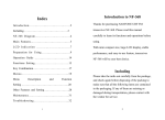
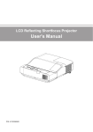
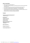
Contents
Introduction…………………………..............................................………………………1
Included.………………....................................................................................................…2
Table of Spare Parts ……………………………………................................................…2
Main Features …………………………………………..............................................……3
Technical Specifications………………….........................................…..…………………4
Know The Radio………………….........................................…………............…..............5
Preparation for Use ……………………….........................................………....…............8
Menu Contents………………………….........................................………...............……12
Operation Guide………………………….............................................…………………20
Auxiliary Functions Description…………….........................................………..………28
Programming Functions…………………….........................................………..….……33
Maintenance…………………….........................................…………..........……….……36
Troubleshooting …………………….....................................……………………………37
Appendix:CTCSS/DCS List………..........................................…………………………38
01
Introduction
Thanks for purchasing ZASTONE ZT-V9 Handheld U/V Band Radio. Please read this manual
Introduction
carefully to learn its functions and operations before using.
With elegant design, stable performance, and easy-to-use feature, transceiver ZT-V9 is developed
for wide using. It offers you a normal communication when you are in the rural area, forest zone,
pasturing area or sea area. The fine appearance of ZT-V9 meets your needs of personality.
Thank you for your support and interest in our products.
Included
Spare Parts
Unit
quantity
Antenna
PC
1
Belt Clip
PC
1
Pack
1
Adaptor
PC
1
Charger
PC
1
User Manual
PC
1
Warranty Card
PC
1
Hang Rope
PC
1
Li-ion Battery Pack
Included
Table of Spare Parts
02
Please take the transceiver from the carton carefully. Please check if the package including the
spare parts as below. If there are any items lost or damaged during moving,please submit claim
immediately to the delivery.
Features
03
Features
1. Frequency:VHF(136MHz-174MHz)
and UHF(400MHz-470MHz)
2. LCD Menu Display
3. Battery: Chargeable 7.4V 1500mAh
4. Wide/Narrow Selectable 25K/12.5K
5. High/Low power Selectable:5w/1w
(VHF)
,4w/1w(UHF)
6. CTCSS:50 /DCS :104
7. ANI Function
8. 99 Channels ,One Emergency ,Can
not be deleted.
9. Scrambler
10. TOT
OFF-15/30/45/60/75/90.../600S
11. VOX
12. Emergency Call
13. PRI
14. BCLO
15.
16.
17.
18.
19.
20.
21.
22.
23.
24.
25.
26.
27.
28.
29.
30.
31.
Free Setting V/U Band
DW
OFF SET
CTCSS/CDCSS
STEP5/6.25/10/12.5/15/20/25K
Scan: VFO/Channel Scanning
SQL:0-9 Level
Light :On/Off
SAVE
MONITOR
Turn on and Automatic Check and
Display the Voltage
Low Battery alert
Key Tone/Lock
APO
FM(87.0MHz~108.0MHz)
PC Programmed and manually Input
Wired Clone
Frequency
Transmit
Output Power
Current
Modulation
Maximum
Frequency Error
Residual Radiation
99
12.5kHz or 25kHz
-20℃~+60℃
7.4V
about 15mA
VHF≤5W UHF≤4W
HI≤1.6A
FM
≤±5kHz or
≤±2.5kHz Selectable
<-60dB
Receive
Sensitivity
SNR
Inter-modulation
Rejection
Audio Power
Mission
Standby Current
≤-122dBm(12dB
SINAD)
≤0.16uV
60dB
≥500mW
≤140mA
15mA
Specification
Channels
Channel Space
Temperature
Voltage
Standby Current
136-174MHz
400-470MHz
04
General
Specification
LCD Definition
LCD Definition
05
Know The Radio
1.Wide/Narrow Band
6.High Power
12.Frequency Offset
7.Frequency Group A
13.Low Battery alert
2.Keypad Lock
8.DCS Setting /CTCSS Setting
14.Priority Channel Scan
3.Scrambler Function
9.CTCSS Indicator
15.APO
4.Power Save
10.Vox
16.Using Frequency Group
5.Low power
11.Tone Setting
17.Frequency Group B
Selectable
06
2.PTT
3.Monitor/FM
4.Emergency Call
5.Down
6.MIC
7.MENU
8.Battery Buckle
9.Battery Pack
10.Number Keypad
11.Up
12.LCD
13.MIC/SP Waterproof Cover
14.Indicator light
15.Volume Knob
16.Belt clip
17.Hand strap hole
Know the Radio
1.Antenna
07
1. [PTT]: Press to Transmit ,Release to Receive.
Know the Radio
Key Instruction
2. [MONI/FM]:Press FM for 1.5 Seconds to turn on FM short press to turn on moni.
3. [CALL]:Press for 1.5 Seconds to Call ;No use for Short press.
4. [MENU]: Menu/Confirm
5. [0]~[9]:Number Keys
6. [UP]/[DOWN]: Up/Down
7. [#/MR]:Press for 1 Second to store the Channels; Hold this to change the VFO and
Channels.
8. [*/BAND]: Press for 1 Second to switch Main Frequency A/B ; Short press to quit.
Preparation For Using
P1
Note: Don’t hold the antenna or hang the keys or
external mic on the Antenna ,in case of
destroying the performance of radio .
P2
Preparation for Using
Install the battery
Install the batter along the rear case of radio
properly as following pictures show:
08
Install the Antenna
Install the antenna as picture shows and
rotate it clockwise till tight.
09
Preparation for Using
Disassembling of battery
Press the fixed buckle of the battery(P1),then
push down the battery off the transceiver(P2)
Install and take off the belt clip
If necessary ,fix the belt clip with two
screws (3*6) as picture shows:
P1
P2
Assembly
Taking Off
Note:1.When installing the belt clip , do not use
any glue to fix screws,otherwise, it will damage
the housing.
2. Take off the belt before disassembling the
battery.
Install external microphone
10
Install the microphone as picture shows,
Preparation for Using
Charging
The battery pack is not fully charger when finished,and please charge it before using.
The battery can not reach the normal capacity for the first time charging after purchasing or
storing it more than two months.However,it will return the normal capacity after charging and
discharging repeatedly 3-5 times.
11
Preparation for Using
Charging steps as below:
1. Insert the AC adaptor line to the charging hole of desk-top .
2. Connect the power with AC adaptor.
3. Put Li-ion battery or Radio with battery on the desk top.
As following pictures show .
P2
P1
P3
Note: 1.Please make sure the battery connect with the touching piece of the charging terminal.
2.Green light indicates power on or the battery is full.Red light indicates the charging just
beginning. Charge in power-off mode, the indicate red light is on, and it is off when finish charging.
3. Do not short-circuit the battery terminals or dispose of batteries in fire.
4.Do not disassemble the housing of the battery.
5. It will take 6 hours for full charge.
Menu Contents
12
1.Keypad Combination
Instruction
Display
[MENU]+[0]
Scrambler On/Off
“S” Flashes
[MENU]+[1]
DW On/Off
DW
[MENU]+[2]
BCLO On/Off
BCLO
[MENU]+[3]
Backlight On/Off
LIGHT
[MENU]+[4]
Key Tone On/Off
KTONE
[MENU]+[5]
APO On/Off
APO
[MENU]+[6]
Power Save On/Off
S
[MENU]+[7]
ANI On/Off
ANI
[MENU]+[8]
Power HIGH/LOW
POWER
[MENU]+[9]
PRI ON/OFF
PRI
[MENU]+[#/MR]
Scan Function
SCAN
[UP]/[DOWN]
Menu and Others
Press [MENU]More than 1s
Key Lock
Menu Contents
Buttons( Silkprinting)
13
Menu Contents
Press [#/MR] More than 1s
Channel Storing/FM Channel Storing
Press [*/BAND] More than 1s
Main Frequency Switch A/B
Press [MENU]
Enter
Press [#/MR]On
Switch working mode :VFO/Channel
Short Press [*/BAND]
Quit
MENU
1.1 SCRM
When turn on this function ,the information has been encrypted .Only same setting radio can get
the information .If not ,others can not be done.
★ Press [MENU],“Menu” display on the Screen ,next line would be blank .
★ Press [0] , “SCRM” display on the Screen ,corresponding status would show next line :On or
Off. Each Operation action would change status.
★ A/B set separately .It is useful under Channel Mode.
1.2 DW
Turn on DW ,Two Frequency would be shown on Screen(A/B). But only can transmit by
Frequency on the Main Screen.
★ Press [MENU],“Menu”display on the Screen ,next line would be blank .
★ Press [1] , “DW”display on the Screen ,corresponding status would show next line :On or
14
Menu Contents
Off. Each Operation action would change status.
★ It is useful under Channel Mode.
1.3 BCLO Setting
BCLO can inhibit radios working when other Signal comes in, in case of stopping other
communication .
★ Press [MENU],“Menu” display on the Screen ,next line would be blank .
★ Press[2], “BCLO”display on the Screen ,corresponding status would show next line :On or
Off. Each Operation action would change status.
★ A/B set separately .It is useful under Channel Mode.
1.4 Back light
After turning on the Light , it would keep. If this function is off ,press this button can show the
light ,but it would be off without any operation 5 seconds.
★ Press [MENU],“Menu” display on the Screen ,next line would be blank .
★ Press[3], “LIGHT”display on the Screen ,corresponding status would show next line :On or
Off. Each Operation action would change status.
★ It is no use under Channel Mode.
1.5 KTONE
Turning on this function, you can bear the keytone every time you press the keypad . If
15
Menu Contents
turning off ,no voice prompts.
★ Press [MENU],“Menu” display on the Screen ,next line would be blank .
★ Press[4], “KTONE”display on the Screen ,corresponding status would show next line :On or
Off. Each Operation action would change status.
★ It is no use under Channel Mode.
1.6 APO
Turning on APO ,if no conduction or any signal received for the radio ,it would be power off
automatically.
★ Press [MENU],“Menu” display on the Screen ,next line would be blank .
★ Press[5], “APO”display on the Screen ,corresponding status would show next line :On or
Off. Each Operation action would change status.
★ It is no use under Channel Mode.
1.7 SAVE
Radio would enter into sleeping mode if no operations or any signal received within 12
seconds ,and checking receiving signals periodically when Power save turns on. If there is radio calling
on the channel,it would keep active status ,then back to sleeping mode. Power save can reduce the
battery cost effectively .
★ Press [MENU],“Menu” display on the Screen ,next line would be blank .
Press[6], “SAVE”display on the Screen ,corresponding status would show next line :On or
Off. Each Operation action would change status.
★ It is no use under Channel Mode.
1.8 ANI
The steps for setting ANI on /off:
★ Press [MENU],“Menu” display on the Screen ,next line would be blank .
★ Press[7], “SAVE”display on the Screen ,corresponding status would show next line :On or
Off. Each Operation action would change status.
★ It is no use under Channel Mode.
1.9 HIGH/LOW POWER
This function is for the setting of transmitting power.
★ Press [MENU],“Menu” display on the Screen ,next line would be blank .
★ Press[8], “POWER”display on the Screen ,corresponding status would show next line :High
or Low. Each Operation action would change status.
★ A/B set separately .It is no use under Channel Mode.
1.10 PRI
The steps for setting the PRI:
★ Press [MENU],“Menu” display on the Screen ,next line would be blank .
★
16
Menu Contents
Press[9], “PRI”display on the Screen ,status would show next line :On or Off. Each
Operation action would change status.
Turning on PRI ,supposed Priority Channel is 1 under Channel Mode,then scanning is
1-2-1-3-1-4…….
1.11 SCAN
Turn on this function to scan VFO and Channel:
★ Press [MENU],“Menu” display on the Screen ,next line would be blank .
★ Press [#/MR], “SCAN” would display on the screen, next line would be “ON”,that
means ,Scanning function is turning on .
★ When scanning ,choose [UP]/[DOWN] to change scan direction, and then press other
buttons to exit.
When FM mode, Scanning function can be used to scan the frequency .Scanning would be
suspended when radios scanned .If need to quit scanning ,do the above again.
1.12 Keypad Lock
When turning on the Key Lock ,other buttons can not be used except the
[MENU]/[PTT]/[CALL] .Press [MENU] more than one second till display
on screen ,then press
[MENU] more than 1 second till
disappearing ,that means Key Unlock.
1.13 Memory Channel
Menu Contents
17
★
18
Menu Contents
Storing the Channels under VFO mode:
★ Under VFO Mode, Select frequency needed to store,then press [#/MR] more than 1 second,
“MEMORY”would display on the screen ,next line would be “01”.
★ Press [UP]/[DOWN],you can store channels (01-09).Or type in two digits as the channel
number .
★ Press [MENU] to store the channel and exit . If press [*/BAND] to exit and not stored.
★ It is no use under channel mode,only can store channels under VFO mode.
1.14 Storing FM channels Under VFO mode
★ Under FM Mode, Select frequency needed to store,then press [#/MR] more than 1 second,
“FM MEM”would display on the screen ,next line would be “01”.
★ Press [UP]/[DOWN],you can store channels (01-16).Or type in two digits as the channel
number .
★ Press [MENU] to store the channel and quit . If press [*/BAND] out of storing .
1.15 Main Frequency Exchange A/B
Press [*/BAND] for 1 second, switch two main frequency ,then select A/B for transmitting and
setting .
Menu Contents
19
2.Menu Contents
Item
Instruction
Contents
01
“RX QT”
Main Fre. RX QT
02
“TX QT”
Main Fre. TX QT
03
“SQL”
0-9(Separately setting on A/B ,Corresponding setting)
04
“TOT”
OFF/15--600S
05
“STEP”
5/6.25/10/12.5/20/25K(Separately setting on A/B,
Corresponding setting)
06
“WN”
WIDE/NARROW(Separately setting on A/B,
Corresponding setting)
07
“OFFSET”
0.0MHz~69.9MHz(Separately setting on A/B,
Corresponding setting)
08
“SHIFT”
0/+/-
09
“SCAN M”
TO/CO/SE
10
“VOX”
OFF/1/2/3/4/5
11
“CALL”
01/CURRENT
12
“TX MODE”
BUSY/MASTER
“PRI SET”
01-99 Channel Selection
14
“ANI CODE”
Display Using Radio ID
15
“ANI SET”
Edit ANI
Note: The following features are set separately between Frequency Group A and B. That means ,it
is useful for Frequency Group A when operating tips display on the Group A .The same with
Group B .
3.1 RX QT Setting
If there is no special calling ,RX QT function makes radio quiet .Setting as following steps:
1) Press [MENU], [MENU] would display on the screen ,next line is blank .Then Press
[UP]or [DOWN] to select “RX QT”.
2) Press [MENU] enter into setting ,first line is “RX QT”,next line shows the status.
3) Press [#/MR] to select OFF/67.0HZ/D023N/D023I ,then press [UP]or[DOWN] to set the
frequency for CTCSS /DCS.
4) Press [MENU] to confirm storing the settings and return ,or press [*/BAND] to exit and
back to standby ,but it can not store the settings.
3.2 TX QT Setting
Menu Contents
3.Menu Instruction
20
13
21
Menu Contents
Setting as following steps::
1) Press [MENU], [MENU] would display on the screen ,next line is blank .Then Press [UP]or
[DOWN] to select“TX QT”.
2) Press [MENU] enter into setting ,first line is “TX QT”,next line shows the status.
3) Press [#/MR] to select OFF/67.0HZ/D023N/D023I ,then press [UP]or[DOWN] to set the
frequency for CTCSS /DCS.
4) Press [MENU] to confirm storing the settings and return ,or press [*/BAND] to exit and back to
standby ,but it can not store the settings.
3.3 SQL
SQL System can eliminate the noise without signal. It not only makes the standby state quiet but
also can save power in standby state obviously.
1) Press [MENU], [MENU] would display on the screen ,next line is blank .Then Press [UP]or
[DOWN] to select“SQL”.
2) Press [MENU] enter into setting ,first line is “SQL”,next line shows the status.
3) Press [UP]or[DOWN] to select 0/1/2/3/4/5/6/7/8/9. 9 is the highest ,1 is the lowest,0 is keeping
squelch .More higher you set ,stronger signal radio receive.
4) Press [MENU] to confirm storing the settings and return ,or press [*/BAND] to quit and back to
standby ,but it can not store the settings.
3.4 TOT
22
Menu Contents
TOT protects radio from being damaged or any caller occupied the channel overtime while using
the radio.Radio would stop transmitting and send the emergency call if radio keeps transmitting and
over the set time (Longest :10 minutes).
1) Press [MENU], [MENU] would display on the screen ,next line is blank .Then Press [UP]or
[DOWN] to select“TOT”.
2) Press [MENU] enter into setting ,first line is “TOT”,next line shows the status.
3) Press [UP]or[DOWN] to select OFF/15/30/45/60/75/90/......./600S.
4) Press [MENU] to confirm storing the settings and return ,or press [*/BAND] to exit and back to
standby ,but it can not store the settings.
3.5 STEP
Choose correct frequency stepping is the basis for setting precise transmitting and receiving
frequency.
1) Press [MENU], [MENU] would display on the screen ,next line is blank .Then Press [UP]or
[DOWN] to select“STEP”.
2) Press [MENU] enter into setting ,first line shows “STEP”,next line shows the status.
3) Press [UP]or[DOWN] to select 5/6.25/10/12.5/20/25K.
4) Press [MENU] to confirm storing the settings and return ,or press [*/BAND] to exit and back to
standby ,but it can not store the settings.
3.6 WN Select
23
Menu Contents
It requests narrow channel spacing in Channel-intensive areas.Therefore it needs to reduce
bandwidth when transmitting so as to avoid some interruption between adjacent channels. Select
Wide/Narrow as following steps:
1) Press [MENU], [MENU] would display on the screen ,next line is blank .Then Press [UP]or
[DOWN] to select“WN”.
2) Press [MENU] enter into setting ,first line is “WN”,next line shows the status.
3) Press [UP]or[DOWN] to select WIDE/ NARROW.
4) Press [MENU] to confirm storing the settings and return ,or press [*/BAND] to exit and back to
standby ,but it can not store the settings.
Note: Choose Narrow as 12.5KHz,Choose Wide as 25KHz.It would display the icon “W”in the bottom
left corner of LCD or “N” in the bottom right corner.
3.7 OFF SET
Offset means the difference between the frequency that user receiving(ascending Frep). Set the
Offset value mainly according to the using offset of the repeater.
1) Press [MENU], [MENU] would display on the screen ,next line is blank .Then Press [UP]or
[DOWN] to select “OFF SET”.
2) Press [MENU] enter into setting ,first line is “OFF SET”, next line shows off set value .
3) Press [UP]or [DOWN] to select offset from 0.0MHz~69.9MHz . If user need to adjust
quickly ,also change it by keypad.
24
Menu Contents
4) Press [MENU] to confirm storing the settings and return ,or press [*/BAND] to exit and back to
standby ,but it can not store the settings.
3.8 SHIFT
Shift Direction would be set as more than or less than receiving frequency .
1) Press [MENU], [MENU] would display on the screen ,next line is blank .Then Press [UP]or
[DOWN] to select“SHIFT”.
2) Press [MENU] enter into setting ,first line is “SHIFT”,next line shows the status
3) Press [UP]or[DOWN] to select OFF/+/-.
4) Press [MENU] to confirm storing the settings and return ,or press [*/BAND] to exit and back to
standby ,but it can not store the settings.
Note : “OFF”means same frequency for transmitting and receiving . “+”means transmitting frequency
higher than receiving frequency; “-” means transmitting frequency lower than receiving frequency.
3.9 SCAN METHOD
Should decide that how to keep scanning when checking out a signal under any situations before
scanning .Choose one method:
★(TO)Time Operation
Radio would stop scanning when checking out a signal. Even signal still keeping after
stopping scanning 5 seconds, radio would continue scanning.
★(CO)Carrier Wave Operation
Radio would stop scanning and keep in the same frequency until signal disappear.
Opeartion
Radios stop in the frequency which has checked out signal and then quit scanning .
Setting steps as following:
1) Press [MENU], [MENU] would display on the screen ,next line is blank .Then Press [UP]or
[DOWN] to select“SCAN M”.
2) Press [MENU] enter into setting ,first line is “SCAN”,next line shows the status.
3) Press [UP]or[DOWN] to select TO/CO/SE.
4) Press [MENU] to confirm storing the settings and return ,or press [*/BAND] to exit and back to
standby ,but it can not store the settings.
3.10 VOX
Do not need to press PTT to control VOX .Just transmit by voice ,if voice stop ,transmit would
stop automatically ,and waiting for receiving .
1) Press [MENU], [MENU] would display on the screen ,next line is blank .Then Press [UP]or
[DOWN] to select“VOX”.
2) Press [MENU] enter into setting ,first line is “VOX”,next line shows the status.
3) Press [UP]or[DOWN] to select OFF/1/2/3/4/5.
4) Press [MENU] to confirm storing the settings and return ,or press [*/BAND] to exit and back to
standby ,but it can not store the settings.
The Voice threshold for VOX can be set by this function .The transmit function is turned on when
voice is higher than Voice threshold.
Menu Contents
25
★(SE)Searching
26
Menu Contents
Note:5= High Sensitivity ,used in low noise condition.
1= Low Sensitivity ,used in high noise condition.
Note: VOX :1/2/3/4/5 ,display on LCD.
3.11 Emergency Call
Channel 01 is emergency call .
1) Press [MENU],then press [UP]or [DOWN] to select “CALL”.
2) Press [MENU] enter into setting ,first line is “CALL”,next line shows the status.
3) Press [UP]or[DOWN] to select 01/CURREN.
4) Press [MENU] to confirm storing the settings and return ,or press [*/BAND] to exit and back to
standby ,but it can not store the settings.
3.12 TX Mode Selection
Turn on the dual band standby, Suppose setting Frequency A as main channel ,but receiving signals
from Frequency B ,user can set to answer by Frequency A ,or by frequency B.
1)Press [MENU],“MENU”shows on the screen,next line is blank.Then press [UP]or [DOWN] to
select “TX MODE”.
2)Press [MENU] enter into setting ,first line is “TX MODE SET”,next line shows the status.
3)Press [UP]or [DOWN] to select “BUSY/MASTER” .
4) Press [MENU] to confirm storing the settings and return ,or press [*/BAND] to exit and back
to standby ,but it can not store the settings.
27
Menu Contents
Note: Choose “BUSY”, users answer this call from the present frequency directly .Choose
“ MASTER” ,no matter what signals radio receives from any channels, user only answer to Main
Frequency .
3.13 PRI SET
1)Press [MENU],then press [UP]or [DOWN] to select “PRI SE”.
2)Press [MENU] enter into setting ,first line is “PRI SET”,next line shows the status.
3)Press [UP]or [DOWN] to select 01-99 as a priority channel.
4)Press [MENU] to confirm storing the settings and return ,or press [*/BAND] to exit and back
to standby ,but it can not store the settings.
Note: 01-99 are channel numbers.
3.14 ANI
This radios programmed with ANI function to identify the radio ID.
1)Press [MENU],then press [UP] or [DOWN] to select “ANI ID”.
2)Press [MENU] enter into setting ,first line is “ANI ID”,next line shows the current ANI code.
3)Press [MENU] to confirm storing the settings and return ,or press [*/BAND] to exit and back
to standby ,but it can not store the settings.
Note: When turn on this function, users should send using radio ANI first ,then can communicate with
others and receive clearly.
3.15 Edit ANI
You can edit ANI content ,3digits at mose
4.1 VFO
In VFO mode, press [UP]or [DOWN] to set the frequency stepcification or directly type in
frequency needed by keypad.
4.2 Channel Storing
★ Common Channel storing ,from 01-100 .
★ 1 One special channel(Emergency channel) ,Number is 01.
Setting steps as following :
1)In VFO mode, choose needed frequency ,and set CTCSS and DCS simultaneously.
Menu Contents
4.Auxiliary Functions
28
1)Press [MENU],then press [UP]or [DOWN] to select “ANI SET”.
2)Press [MENU] enter setting ,first line is “ANI SET”,next line shows ANI code and the first
code flashes.
3)First digit is group number ,then press [UP]or [DOWN] to select 0-9.
4)After editing first digit ,then press [#] to editing second and third digit as ID .The number range
is 01-80 (For example ,ID is 01 ,second digit is 0 ,third digit is 1 ).
5)Press [MENU] to confirm storing the settings and return ,or press [*/BAND] to exit and back
to standby ,but it can not store the settings.
Note: If want to delete or edit former digit ,press [#] till the digit which you want to modify flashes.That
means you can modify .
29
Menu Contents
2)Press [MR] for 2 second ,LCD shows channel 01-100 flashes ,Press [UP]or [DOWN] to
select one channel from 01-100.
3)Press [MENU] again to store the frequency .
4)Still working under VFO mode ,and do again the above operations and type in other
frequency to store channels.
Note: User can store 100 channels(maximum) when radio in the single Frequency .When turning
on dual band function ,user can store 50 channels (maximum) for each Frequency A and Frequency
B.
4.3 Switch Channel Mode
Press and hold[MR] to turn on the radio then switch to the channel mode. Do again ,change into
VFO mode.Channels in Channel Mode is stored under VFO mode or programmed by PC .Change
channels in Channel Mode by reset in VFO mode or re-programmed by PC.
4.4 1750 Tone
When user wants to use the radio with repeater ,the repeater can be turned on after receiving the
1750 signal.Meanwhile,press and hold[CALL]key for more than 1 second to keep transmitting 1750
signal.
▲ Radios turn on channel 01 or Current using channel.for transmitting(Setting by Menu 11)
▲ Indicators flashes red and sending the signal .
▲ 1750 Tone can act as an emergency call.But user should adjust the volume to max,so that the
radio can issue an lounder emergency alarm.
Press PTT to withdraw the emergency call.
It is good and quick method to ask for help when outgoing for some activities .
Emergency call can be used repeater radios and transfer information ,but need about 1 second 1750
signal and turn on this function first .
4.5(FM)
a) Press and hold [MONITOR/FM] for more than 2 seconds to FM mode.
b) Press [UP]or [DOWN] to adjust the FM frequency (Range 87.0~108.0MHz,step 100KHZ,
Long press [UP]or [DOWN] to choose frequency 。)
c) Press [MONITOR/FM] again for more than 2 seconds to exit FM .
u Keep radio working first when still in FM mode .The radio would change to communicate
with others automatically in FM mode when signals comes in.
u Under FM mode: Press MR to enter storing FM channels ( 16 channels)
FM scanning
FM Scanning :Under FM mode, press [MENU] ,then [MR] button to scan the whole
frequency :start from the current frequency ;Press [UP] to scan from low to high .Press [DOWN] to
scan from high to low .Then stop at the scanned frequency when scan the radio station with
signal,press [UP]or [DOWN] to keep scanning ,or press others buttons to quit.
During scanning ,if need to store the current radio ,should press any buttons to quit scanning
and store channels according to the following steps .
▲
30
Menu Contents
31
Menu Contents
FM Channel Storing
Radio can store 16 channels maximum ,from 01-16 .
Steps following :
A. Under FM full screen Mode ,choose channel which have received .
B. Press [MR] for 2 second ,LCD shows 01-16 and flashes ,then press [UP]or [DOWN] to select
one from 01-16 .
C. Press [MENU] again to store it .
D. Select a radio station with other frequency,then repeat the steps above to store it.
★Select Stored F M C hannel
Under FM Mode, press MR and then press [UP]or [DOWN] to select stored channel from 01-16 .
Press MR to quit storing .
4.6 Low Battery Detection
i.
Working in Voltage higher 6.5 V (Battery shows 1-2 Grid).
ii.
Transmitter and receiver work normally ,but red indicator flashes when voltage lower than
6.5V ,but higher than 6.2V (Battery shows 1 Grid).
iii.
Voltage higher than 6.1V but lower than 6.3V ( battery is blank ) ,Receiver works
normally ,alarm “Di Di” by every 20 seconds ; Transmit works nomally ,but red
indicator flashes.
iv.
Voltage lower than 5.9V ( battery is blank ) ,receiver works , alarm every 2
seconds ,transmitting prohibited.
32
Menu Contents
4.7 Wired Cloned
a) Press PTT 和 MONI turn on the radio till hear“Di”tips ,then release . Now LCD shows
“ CLONE” . Ready to cloning when Orange indicator flash .
b) Connect the host radio with the assistant radio by transfer cable and turn on the power of
assistant radio.
c) Press MONI on the main radio , red indicator flashes and cloned radio green indicator
flashes.That means ready to clone;After 28 seconds,cloning is over and main radio would turn
back to “ Ready cloning” and shows “ CLONE” ,cloned radio would reset automatically .
d) If failing to clone ,main radio shows “ERR” ,cloned radio would reset automatically .
Then ,press MONI on the main radio and LCD shows “CLONE” ,please check if wires
contact well . Repeat step C to clone.
e) If need to clone with several radios, please turn off the cloned radios ,and take off the
cable ,change another cloned radio, then repeat step B&C.To quit cloning ,please turn off the
radio and then turn on again .
Programming Functions
33
Programming Functions
1. Channel working frequency
The dealer can use ZT-V9 software to set the transmitting frequency and receiving frequency.
2. DCS/CTCSS
The dealer or manufacturer can use ZT-V9 software to program digital code squelch (DCS) and
Continuum tone squelch system (CTCSS).
When a certain channel has set CTCSS or DCS, the squelch circuit can be turned off while
receiving the same CTCSS and DCS signal.Likewise,only if the radio signal,you can hear the
transmitting signal.If others use the different CTCSS/DCS in the channel you are the different
CTCSS/DCS in the channel you are using to call,the squelch circuit can not be turned off,only yellow
indicator flashes to prompt.
3. Squelch level setting
The dealer or manufacturer can use ZT-V9 software to program the squelch level from 0- 9.
4. Battery save
If the transceiver is set battery save function, the LCD will show “S”. The transceiver will into
power save state after stopping communication within 10 seconds.
5. Keypad Tone On/Off
34
Programming
Specification Functions
One clock symbol displays on the LCD when "Beep" sound is on, indicator sounds for pressing
keypad each time.Otherwise,no indicator sound heard while turning on the radio and pressing the
keypad.
6. Power selection
You can select power transmit for every channel, when you select high power, the LCD will
display “HI”, when you select low power, the LCD will show “LO” (Factory default LOW).
7.Scan method and parameter
A. The description scan method
In scan mode the transceiver will scan every channel, when a signal has been detected on a
channel, the scanner will pause and wait until the signal disappears. The dealer can set the delay time.
During the time if the signal was received again, the transceiver will continue to keep the channel
within the delay time until the signal disappears,and over the delay time then the transceiver will
return to scan state (Factory default 3 seconds).
B. Start-up scan
Long press [SCAN] about 2 seconds to start scanning.
a.Star scan from the current channel as per the channel number increased by degrees;
b.Yellow light flashes;
c.When a channel receive signal that match the type,the yellow light will keep showing
35
Programming Functions
and squelch will be off. Press [SCAN] key to exit the scan state.
C. Priority scan
The dealer or manufacturer can use ZT-V9 software to set 2 kinds of priority scan:
a. Set the fixed channel as prior scan channel(Note: the channel can not be empty);
b. Set the selected channel as prior scan channel(current working channel is the selected channel).
If you have already set the priority scan channel, when fail to receive the matched signal during
scanning, it will return to scan the prior channel while scanning every channel.
8. BCLO Setting
During communication , you can turn on BCLO function in case of being interrupted by others. At
that time ,there is “Di Di” sound from speaker when press PTT ,also “BCLO” would display on the
screen .
9. ANI
Distributors and factory can set the ANI code by ZT-V9 software , the code can be set 3 digits at
most to identify the ANI code of current radio.
10.Scrambler
Distributors and factory can program scrambler to avoid interruption from other radios or
confidential calls .Radio can receive clear information when setting same scrambler.
Maintenance
36
Transceiver ZT-V9 you purchased is an exactitude design electronic products and please use it
carefully. Following maintenance ways may help extend its lifetime.
damage to the device.
2.Don’t use or charge the transceiver in explosive condition(The air contains a lot of fine sand, dust,
and a place where a large number of chemicals).
3.Turn off the transceiver when you are in gas station.
4.Please don’t put the transceiver in sun or hot place for long time, because the high temperature will
shorten use life of electronic parts and cause distortion to plastic parts.
5.Please keep the transceiver dry, because rain and moisture will erode the electronic circuits.
6.Please power off the transceiver and remove its battery pack immediately once there is peculiar smell
or smog emit from the device.
Maintenance
1.Please don’t try to disassemble the transceiver because non-technicians’ processing may cause
Troubleshooting
37
Troubleshooting
Trouble
No reaction when power-on
Unable to
talk with other
members in the same group
Talking distance is short
Other
(not
from
group
members) sound heard in
channels.
The battery used out soon after
recharged.
People receive your Voice is
low or broken
Water inlet
Solution
●The battery pack has been exhausted. Please change a new battery or recharge
the battery.
● The battery pack may be not installed correctly. Please install it again.
● Please check the frequency and CTCSS/DCS you use are the same as other
members use in the same group.
● The distance between you and other group members may be too far. Please
check if you are in the cover range of other group transceivers.
● Make sure the antenna screws tight and contact well
● Make sure if using the original antenna from the manufacturer.
● The dealer or user set the higher squelch lever, please reduce the lever.
● Change the frequency
● Please change your CTCSS/DCS NO. And it has to change all signal sound
of the group transceivers.
● The use-life of the battery is over, please change new battery.
● If the battery has been completely charged
● Check if the MIC hole is jammed
● Take out the battery at once when water inlet and dump the water, put it in a
draft to dry it. Make sure to send it to maintenance station in a short time.
Appendix: CTCSS/ DCS List
38
CTCSS 50
DCS 104
023
025
026
031
032
036
043
047
051
053
054
065
071
072
073
074
114
115
85.4
88.5
91.5
94.8
97.4
100.0
103.5
116
122
125
131
132
134
143
145
152
107.2
110.9
114.8
118.8
123.0
127.3
131.8
155
156
162
165
172
174
205
212
223
225
226
243
244
245
246
251
252
255
136.5
141.3
146.2
151.4
156.7
159.8
162.2
261
263
265
266
271
274
306
311
315
165.5
167.9
171.3
173.8
177.3
179.9
183.5
325
331
332
343
346
351
356
364
365
371
411
412
413
423
431
432
445
446
186.2
189.9
192.8
196.6
199.5
203.5
206.5
452
454
455
462
464
465
466
503
506
210.7
218.1
225.7
229.1
233.6
241.8
250.3
516
523
526
532
546
565
606
612
624
254.1
627
631
632
654
662
664
703
712
723
731
732
734
743
754
CTCSS/DCS List
67.0
69.3
71.9
74.4
77.0
79.7
82.5