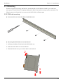
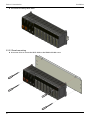
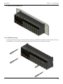
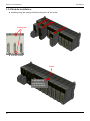
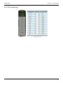
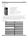
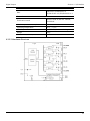
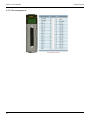
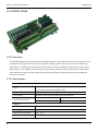
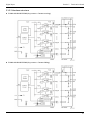
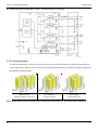
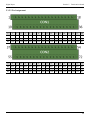
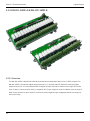
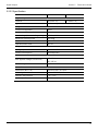
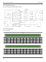
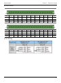
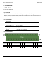
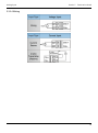
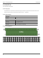
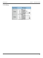
1
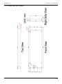
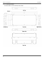
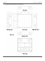
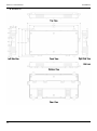
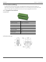
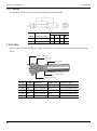
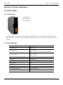
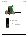
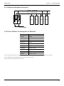
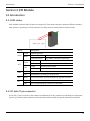
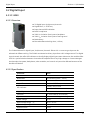
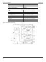
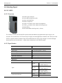
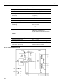
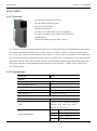
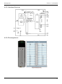
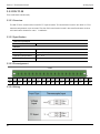
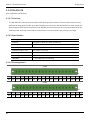
iDCS-8000 Remote Rugged I/O System with Redundancy Hardware User's Manual Revision History Revision Date Description of Change 1.42 2013/06/28 Adding analog module to this hardware user’s manual 1.41 2013/06/03 Adding some description for the section of mounting. 1.40 2013/05/22 Document release Preface Warranty All products manufactured by ICP DAS are under warranty regarding defective materials for a period of one year from the date of delivery to the original purchaser. Warning ICP DAS assumes no liability for damages resulting from the use of this product. ICP DAS reserves the right to change this manual at any time without notice. The information furnished by ICP DAS is believed to be accurate and reliable. However, no responsibility is assumed by ICP DAS for its use, or for any infringements of patents or other rights of third parties resulting from its use. Copyright Copyright © 2013 by ICP DAS CO., LTD. All rights are reserved. Trademark The names used for identification only may be registered trademarks of their respective companies. Table of Contents SECTION 1 INTRODUCTION ......................................................................................................................... 9 1.1 PRODUCT OVERVIEW.................................................................................................................................. 9 1.2 FEATURE...................................................................................................................................................... 10 1.3 HARDWARE STRUCTURE ........................................................................................................................... 11 1.4 HARDWARE LIST ........................................................................................................................................ 12 1.5 INSTALLATION ............................................................................................................................................ 13 1.5.1 Environment Specification ....................................................................................................... 13 1.5.2 Dimensions .................................................................................................................................... 13 1.5.2.1 Module..................................................................................................................................... 13 1.5.2.2 iDCS-8000 Body (Module Plugged) ............................................................................. 14 1.5.2.3 FRMK (Wall mount panel) ................................................................................................ 15 1.5.2.4 Termination Board .............................................................................................................. 16 1.5.3 Mounting ........................................................................................................................................ 19 1.5.3.1 DIN-rail mounting ............................................................................................................... 19 1.5.3.2 Panel mounting .................................................................................................................... 20 1.5.3.3 Wall mounting ...................................................................................................................... 21 1.5.4 Module Installation ..................................................................................................................... 22 1.5.5 Wiring ............................................................................................................................................... 23 1.5.6 Field Grounding ........................................................................................................................... 24 1.5.6.1 Grounding .............................................................................................................................. 25 1.5.7 Terminals and Wiring ................................................................................................................. 27 1.5.7.1 Pluggable Terminal Blocks ............................................................................................... 27 1.5.7.2 Wiring ....................................................................................................................................... 28 1.5.8 Cable ................................................................................................................................................. 28 SECTION 2 POWER MODULES .................................................................................................................. 29 2.1 FPM-D2440 ............................................................................................................................................ 29 2.1.1 Overview ......................................................................................................................................... 29 2.1.2 Specification .................................................................................................................................. 29 2.1.3 Pin Assignment............................................................................................................................. 30 2.1.4 LED Indicator ................................................................................................................................. 30 2.1.5 Internal Hardware Structure .................................................................................................... 31 2.1.6 List of Power Consumption of Module ............................................................................... 31 SECTION 3 COMMUNICATION MODULE ............................................................................................. 32 3.1 FCM-MTCP ............................................................................................................................................. 32 3.1.1 Overview ......................................................................................................................................... 32 3.1.2 Specification .................................................................................................................................. 32 5 Table of Contents 3.1.3 Switches ........................................................................................................................................... 33 3.1.4 LED Indicators ............................................................................................................................... 33 3.1.5 Ethernet Port ................................................................................................................................. 34 SECTION 4 I/O MODULE .............................................................................................................................. 35 4.1 INTRODUCTION ......................................................................................................................................... 35 4.1.1 LED status ....................................................................................................................................... 35 4.1.2 D-Sub 37 pin connector............................................................................................................ 35 4.1.3 Timing Characteristics ............................................................................................................... 36 4.2 DIGITAL INPUT ........................................................................................................................................... 37 4.2.1 F-8040 .............................................................................................................................................. 37 4.2.1.1 Overview ................................................................................................................................. 37 4.2.1.2 Specification .......................................................................................................................... 37 4.2.1.3 Hardware Structure ............................................................................................................. 38 4.2.1.4 Pin Assignment..................................................................................................................... 39 4.3 DIGITAL OUTPUT ....................................................................................................................................... 40 4.3.1 F-8041 .............................................................................................................................................. 40 4.3.1.1 Overview ................................................................................................................................. 40 4.3.1.2 Specification .......................................................................................................................... 40 4.3.1.3 Hardware Structure ............................................................................................................. 41 4.3.1.4 Pin assignments ................................................................................................................... 42 4.4 ANALOG INPUT.......................................................................................................................................... 43 4.4.1 F-8015 .............................................................................................................................................. 43 4.4.1.1 Overview ................................................................................................................................. 43 4.4.1.2 Specification .......................................................................................................................... 43 4.4.1.3 Hardware Structure ............................................................................................................. 44 4.4.1.4 Pin assignments ................................................................................................................... 45 4.4.2 F-8017C1 ......................................................................................................................................... 46 4.4.2.1 Overview ................................................................................................................................. 46 4.4.2.2 Specification .......................................................................................................................... 46 4.4.2.3 Hardware Structure ............................................................................................................. 47 4.4.2.4 Pin assignments ................................................................................................................... 48 4.4.3 F-8017C2 ......................................................................................................................................... 49 4.4.3.1 Overview ................................................................................................................................. 49 4.4.3.2 Specification .......................................................................................................................... 49 4.4.3.3 Hardware Structure ............................................................................................................. 50 4.4.3.4 Pin assignments ................................................................................................................... 51 4.4.4 F-8017CH ........................................................................................................................................ 52 4.4.4.1 Overview ................................................................................................................................. 52 4.4.4.2 Specification .......................................................................................................................... 52 4.4.4.3 Hardware Structure ............................................................................................................. 53 6 Table of Contents 4.4.4.4 Pin assignments ................................................................................................................... 54 4.4.5 F-8019 .............................................................................................................................................. 55 4.4.5.1 Overview ................................................................................................................................. 55 4.4.5.2 Specification .......................................................................................................................... 55 4.4.5.3 Hardware Structure ............................................................................................................. 57 4.4.5.4 Pin assignments ................................................................................................................... 57 4.5 ANALOG OUTPUT...................................................................................................................................... 58 4.5.1 F-8028CV ........................................................................................................................................ 58 4.5.1.1 Overview ................................................................................................................................. 58 4.5.1.2 Specification .......................................................................................................................... 58 4.5.1.3 Hardware Structure ............................................................................................................. 60 4.5.1.4 Pin assignments ................................................................................................................... 60 4.5.2 F-8028CH ........................................................................................................................................ 61 4.5.2.1 Overview ................................................................................................................................. 61 4.5.2.2 Specification .......................................................................................................................... 61 4.5.2.3 Hardware Structure ............................................................................................................. 62 4.5.2.4 Pin assignments ................................................................................................................... 63 SECTION 5 TERMINATION BOARD .......................................................................................................... 64 5.1 DIGITAL INPUT ........................................................................................................................................... 64 5.1.1 DN-DIO-M...................................................................................................................................... 64 5.1.1.1 Overview ................................................................................................................................. 64 5.1.1.2 Specification .......................................................................................................................... 64 5.1.1.3 Pin assignment ..................................................................................................................... 65 5.1.1.4 Wiring ....................................................................................................................................... 65 5.1.2 DN-DI-32DW................................................................................................................................. 66 5.1.2.1 Overview ................................................................................................................................. 66 5.1.2.2 Specification .......................................................................................................................... 66 5.1.2.3 Hardware structure ............................................................................................................. 67 5.1.2.4 Jumper Setting ..................................................................................................................... 68 5.1.2.5 Pin Assignment..................................................................................................................... 69 5.1.2.6 Wiring ....................................................................................................................................... 70 5.2 DIGITAL OUTPUT ....................................................................................................................................... 72 5.2.1 DN-DIO-M...................................................................................................................................... 72 5.2.1.1 Overview ................................................................................................................................. 72 5.2.1.2 Specification .......................................................................................................................... 72 5.2.1.3 Pin assignment ..................................................................................................................... 73 5.2.1.4 Wiring ....................................................................................................................................... 73 5.2.2 DN-DO-16DR-A & DN-DO-16DR-B.................................................................................... 74 5.2.2.1 Overview ................................................................................................................................. 74 5.2.2.2 Specification .......................................................................................................................... 75 7 Table of Contents 5.2.2.3 Hardware structure ............................................................................................................. 76 5.2.2.4 Pin Assignment..................................................................................................................... 76 5.2.2.5 Wiring ....................................................................................................................................... 77 5.3 ANALOG INPUT.......................................................................................................................................... 78 5.3.1 DN-AIO-M ...................................................................................................................................... 78 5.3.1.1 Overview ................................................................................................................................. 78 5.3.1.2 Specification .......................................................................................................................... 78 5.3.1.3 Pin assignment ..................................................................................................................... 78 5.3.1.4 Wiring ....................................................................................................................................... 79 5.3.2 DN-RTD-M ..................................................................................................................................... 80 5.3.2.1 Overview ................................................................................................................................. 80 5.3.2.2 Specification .......................................................................................................................... 80 5.3.2.3 Pin assignment ..................................................................................................................... 80 5.3.2.4 Wiring ....................................................................................................................................... 81 5.3.3 DN-TC-M ........................................................................................................................................ 82 5.3.3.1 Overview ................................................................................................................................. 82 5.3.3.2 Specification .......................................................................................................................... 82 5.3.3.3 Pin assignment ..................................................................................................................... 82 5.3.3.4 Wiring ....................................................................................................................................... 82 5.3.4 DN-AIH-08 ..................................................................................................................................... 84 5.3.4.1 Overview ................................................................................................................................. 84 5.3.4.2 Specification .......................................................................................................................... 84 5.3.4.3 Pin assignment ..................................................................................................................... 84 5.3.4.4 Wiring ....................................................................................................................................... 85 5.4 ANALOG OUTPUT...................................................................................................................................... 86 5.4.1 DN-AIO-M ...................................................................................................................................... 86 5.4.1.1 Overview ................................................................................................................................. 86 5.4.1.2 Specification .......................................................................................................................... 86 5.4.1.3 Pin assignment ..................................................................................................................... 86 5.4.1.4 Wiring ....................................................................................................................................... 87 8 Product Overview Section 1 Introduction Section 1 Introduction The iDCS-8000 is distributed modular I/O which communicates with numerous controllers. The iDCS-8000 provides easy installation of the I/O modules and process cabling. It is highly modularized and flexible, so that I/O modules can be combined to suit many applications. The iDCS-8000 can be mounted in many configurations to fit most requirements, both in single or fully redundant applications. 1.1 Product Overview The iDCS-8000 is a modular remote I/O system. It provides easy installation of the I/O modules and process cabling. It is highly modularized and flexible, so that the I/O modules can be combined to suit many applications including the most types of signals, digital, analog, counter and HART. The station of an iDCS-8000 system consists of power module, communication module, I/O modules and termination board. The power module provides the isolated power to iDCS-8000 system. The communication module is the interface to the iDCS-8000 I/O modules. The iDCS-8000 I/O modules sense or control the device in the field. Termination boards are used to connect between signals to/from the field and I/O modules. All of these modules can be configured into single or redundant operation. 9 Section 1 Introduction Feature 1.2 Feature The iDCS-8000 is an open comprehensive, distributed, process I/O system. It communicates with controller over industry-standard field buses. It brings benefit for users install to iDCS-8000 in the field, to close to sensors and actuators, to reduce the installation cost by reducing the cost of cabling. Comprehensive The iDCS-8000 offers cost-effective solutions to practically all needs for field-device, including basic analog and digital I/O, pulse and HART, as well as high-integrity solutions. Flexible The I/O modules plugged in iDCS-8000 station can be configured into single or redundant operation. Users can easily upgrade I/O security in a same station by adding same I/O module and configuring into redundant operation without any additional wiring. Wide industry-standard support The iDCS-8000 provides connectivity to most popular industry-standard to communicate with controller, and makes iDCS-8000 I/O compatible with various controller or PLC. The up-to-date I/O The I/O modules plugged in the iDCS-8000 station will automatically update I/O data to communication module. This feature not only decreases the delay for updating I/O data but also acquire the up-to-date I/O data. I/O redundant switching < 1ms The iDCS-8000 features a tiny time for I/O redundant switching within maximum 1ms. Reliable The iDCS-8000 offers availability-improving feature such as: - Hot swap of modules. A faulty I/O module can be replaced on-line without powering the station down and without affecting the rest of the station. - The iDCS-8000 system also ensures that only right type of modules can be inserted when to replace on-line. 10 - Automatically re-configure same parameter when plugging a replaced module. - Redundancy options in all modules, power, communication, I/O. Hardware Structure Section 1 Introduction 1.3 Hardware Structure The iDCS-8000 is made by the combination of components of the backplane, power modules, communication modules, I/O modules and an termination board. Backplane Power Communication IO Backplane The backplane consists of 2 slots of power, 2 slots of communication and 8 single or 4 pairs of redundant I/O modules. Power Module It provides the power to the system. It also bypasses 24VDC to the I/O module to support passive loop. This module has hot-swappable and redundant functions. Communication Module This module is a configurable communication interface that performs operation such as signal processing, automatically re-configuration, HART pass-through and configuration of I/O modules. The module connects to the controller or PLC through of the most popular industrial fieldbuses. I/O Module The iDCS-8000 I/O modules can be inserted and removed from backplane without disturbing system operation. Termination Board The termination boards provide the connection to the field. It also reduces the wiring and installation effort. 11 Section 1 Introduction Hardware List 1.4 Hardware List The equipment that is used as part of the iDCS-8000 station is presented in the following table. Type Module Name Description Communication Module FCM-MTCP Modbus/TCP Communication Module Power Module FPM-D2440 24VDC Input,35W@5VDC Output Digital Digital I/O Input Digital Output F-8040 Analog I/O Input 32 digital output channel, current sinking, open collector F-8015 8 analog input channels, 3-wire RTD, Pt100, Pt1000 F-8017C2 F-8017CH 8 differential analog input channels, 4~20mA, with loop power for passive loop 16 differential analog input channels, 4~20mA 8 differential analog input channels, 4~20mA, HART interface, with loop power for passive loop F-8019 8 analog input channels, Thermocouple, mV, ±5V, ±10V Analog F-8028CV 8 analog output channels, 4~20mA, ±5V, ±10V Output F-8028CH 8 analog output channels, 4~20mA, HART interface DN-DIO-M Termination board for digital I/O modules DN-DI-32DW Termination board for digital input modules DN-DO-16DR-A Termination Board Accessories common for 32 channels F-8041 F-8017C1 Analog 32 digital input channels, current sinking / sourcing, one DN-DO-16DR-B Termination board for digital output with power relay for channel 0~15 Termination board for digital output with power relay for channel 16~31 DN-AIO-M Termination board for analog I/O modules DN-AIH-04 Termination board for HART analog input module DN-RTD-M Termination board for RTD I/O modules DN-TC-M Termination board for Thermocouple I/O modules 4SIPP-801W-CAG Dummy I/O cover FRMK 19” mounting panel CA-01 D-Sub 37pin Female-Male 1m Cable,24AWG,180 UL-2464 CA-02 D-Sub 37pin Female-Male 2m Cable,24AWG,180 UL-2464 CA-03 D-Sub 37pin Female-Male 3m Cable,24AWG,180 UL-2464 CA-05 D-Sub 37pin Female-Male 5m Cable,24AWG,180 UL-2464 。 。 。 。 。 CA-10 12 D-Sub 37pin Female-Male 10mCable,24AWG,180 UL-2464 Installation Section 1 Introduction 1.5 Installation 1.5.1 Environment Specification The following table is the absolute maximum rating of the environmental specification for the iDCS-8000. Parameter Specification Operating Temperature -25℃~75℃ Operating Humidity 5 ~ 95 % RH, non-condensing Storage Temperature -40℃~85℃ Storage Humidity 5 ~ 95 % RH, non-condensing Operating Voltage 24VDC Maximum Operating Voltage 24VDC + 10% 1.5.2 Dimensions 1.5.2.1 Module 13 Section 1 Introduction Installation 1.5.2.2 iDCS-8000 Body (Module Plugged) Units: mm 14 Installation Section 1 Introduction 1.5.2.3 FRMK (Wall mount panel) 15 Section 1 Introduction 1.5.2.4 Termination Board DN-DO-16DR-A / DN-DO-16DR-B / DN-DI-32DW 16 Installation Installation Section 1 Introduction DN-DIO-M / DN-AIO-M / DN-TC-M / DN-RTD-M 17 Section 1 Introduction DN-AIH-04 18 Installation Installation Section 1 Introduction 1.5.3 Mounting There are 3 types of mounting, the DIN-rail, panel and wall, for iDCS-8000 to install in your cabinet or other places. The iDCS-8000 is originally designed for DIN-rail and wall mounting by the mechanism. The following section will describe how to mount the iDCS-8000 in different type. 1.5.3.1 DIN-rail mounting Use screw drive to mount the DIN-rail with M4 screw Mounting the iDCS-8000 unit to the DIN-rail 1. Pull down the DIN-rail lock behind the iDCS-8000 unit 2. Attach the iDCS-8000 unit on the DIN-rail 3. Slide the DIN-rail lock up to fix iDCS-8000 to the DIN-rail 2 1 3 19 Section 1 Introduction Successful mounting iDCS-8000 1.5.3.2 Panel mounting Use screw drive to mount the iDCS-8000 to the FRMK with M4 screw 20 Installation Installation Section 1 Introduction Then mount the FRMK panel 1.5.3.3 Wall mounting The steps of wall mounting are same as panel mounting. The difference between panel and wall mounting is the FRMK unit. The 4 M4 screws directly screwed iDCS-8000 unit to the plane you want. 21 Section 1 Introduction Installation 1.5.4 Module Installation Installing along the guiding rail then pushing into 48-pin socket Guiding rail Lock the module Locker Push following this direction to lock the module 22 Installation Section 1 Introduction 1.5.5 Wiring Single Operation Redundant Operation 23 Section 1 Introduction Installation 1.5.6 Field Grounding The hardware circuit is easily broken by the noise, ESD (Electrostatic Discharge), EFT (Electrical Fast Transient), and surge, in the field. The iDCS-8000 provides a frame ground to gain noise immunity. This can prevent the damage caused by noise and increase the system stability. There are many ways to ground iDCS-8000 to earth ground. The most common way to ground to earth is by using the sheet metal behind the iDCS-8000. When mount the iDCS-8000 with DIN-rail in cabinet, the sheet metal will attach to the conductor of the cabinet to lead to ground. 24 Installation Section 1 Introduction 1.5.6.1 Grounding In order to prevent the operators to get an electric shock and external noise to affect iDCS-8000 system, the cabinet of the iDCS-8000 must set earthed. And all the metal that the operators might touch must set earthed. The grounded system must follow “Electrical Equipment Technical Standard” Class D specification and the earth resistance must be below 100Ω. (Note: There is a 3 kVDC high-tension condenser between the S.G and F.G of iDCS-8000). The grounded system of the iDCS-8000 must follow Class D specification. When grounding, please do not share the ground point of the iDCS-8000 with other power system. And the distance between two ground points must greater than 10 meters. 25 Section 1 Introduction 26 Installation Installation Section 1 Introduction 1.5.7 Terminals and Wiring The termination board of the iDCS-8000 is a bridge between field devices and I/O modules. The termination board provides a pluggable terminal block to connect field devices to termination board. Users can easily replace the termination board by removing the pluggable terminal block. 1.5.7.1 Pluggable Terminal Blocks Specification Parameters Value Tightening Torque 0.6 Nm / 5.31048 Lb.in Wire Size 12~24 AWG Insulating Material PA Inflammability Class UL 94 V0 Nominal Current 12 A Nominal Voltage 250 V Contact Tin plated Screw Thread M3 Operating Temperature -40℃ to +105℃ Dimension (Unit: mm) 27 Section 1 Introduction Installation 1.5.7.2 Wiring The following table is the recommended wire and end-cord terminals. Deiemsion (mm) Wire Recommended AWG conductor (mm) L F C W 20 0.5 16 10 1 2.6 18 0.75 18 12 1.2 2.8 1.5.8 Cable There are three cables with different length can be used to connect the I/O module and the termination board. Cooper conductor Drain wire PVC jacket Aluminum mylar SR-PVC insulation 28 Model Length Material Rated Temp. Connector Type CA-01 1m Semi-rigidPVC 80℃ 37P D-Sub Male Cable CA-02 2m Semi-rigidPVC 80℃ 37P D-Sub Male Cable CA-03 3m Semi-rigidPVC 80℃ 37P D-Sub Male Cable CA-05 5m Semi-rigidPVC 80℃ 37P D-Sub Male Cable CA-10 10m Semi-rigidPVC 80℃ 37P D-Sub Male Cable FPM-D2440 Section 2 Power Modules Section 2 Power Modules 2.1 FPM-D2440 2.1.1 Overview 24VDC input Diagnostic Redundancy The FPM-D2440 is a power module. It offers the isolated power source to the iDCS-8000 system. The FPM-D2440 can be used to single or redundant application. It also has diagnostic to make system more reliable. 2.1.2 Specification Parameter Value Voltage input 24VDC±20% Voltage output Current output 5 VDC±2% 24VDC (Depending on input power source) 5VDC: 7.5A max 24VDC: 5A max Insulation resistance 1000MΩ Isolation 1500VDC min Short circuit protection Yes (Continuous) Redundancy Yes Operating temperature -25°C ~ +75°C Dimension 31mm x 91mm x 115mm (W x L x H) Conducted emission EN55022 Class A Radiated emission EN55022 Class A 29 Section 2 Power Modules FPM-D2440 2.1.3 Pin Assignment PW R FP M- D2 44 0 PWR GND F.G Pin Description PWR 24 VDC P.GND Ground F.G Frame Ground 2.1.4 LED Indicator LED Status Description On Normal operation No input or invalid input PWR Off Output lower than 4.5VDC Module failure Output overloaded 30 FPM-D2440 Section 2 Power Modules 2.1.5 Internal Hardware Structure 24VDC - I/O module 5VDC - control circuit MCU MCU IOM IOM 24 VDC input 2.1.6 List of Power Consumption of Module Model Name Maximum Output Current F-8040 1.8 W F-8041 2.3 W F-8017C1 1.5 W F-8017C2 2.2 W F-8017CH 1.2 W + 7.5W F-8028CV N/A F-8028CH 0.5 W + 10 W F-8015 1W F-8019 1.3 W F-8084 1.3 W + 1.1 W 1 2 3 1. 24V is used for the power in passive loop. The power consumption depends on the number of sensors are connected. 2. This is left blank intentionally. Because this module is under developing. 3. The power consumption depends on the load. 31 Section 3 Communication Module FCM-MTCP Section 3 Communication Module 3.1 FCM-MTCP 3.1.1 Overview Modbus/TCP Hardware selectable node ID Redundancy LED indicators for local diagnostic The FCM-MTCP is a communication module with Mudbus/TCP through ethernet port. The Modbus/TCP is a standard protocol commonly used in industrial applications. The FCM-MTCP can be used for the Modbus/TCP client to access I/O modules. It is built-in two rotary switches to easily configure node ID without utility. There are also 3 LED indicators for system diagnostic and 2 LED indicators for network status, users can locally check system and network status. The FCM-MTCP not only offers single operation but also redundant, this benefit brings I/O system more reliable. 3.1.2 Specification Parameter LAN Port 10/100BASE-TX (Auto negotiating, Auto MDIX) Protocol Modbus/TCP LED indicators 1 Power, 2 Fault, 1 Link/Active/Speed Power consumption 2W Redundant Yes Operating temperature -25°C ~ +75°C Isolation 32 Value 3000VDC (Between LAN port and F.G) 1000VDC (Between LAN port and backplane) FCM-MTCP Section 3 Communication Module 3.1.3 Switches The switches are used for the value of the 4th IP address. The valid number of the address is from 1 to 254. The other 3 addresses can be configured through MiniOS7 Utility. 3.1.4 LED Indicators HF RUN LF LED HF SW1 RUN SW2 LF LAN LNK ACT LNK ACT Status On:Heavy fault Off:Normal On:Module Power On Off:Module Power Off On:Light fault Off:Normal On:Ethernet Link Establish Off:No Ethernet Link On:Ethernet Activity Off:No Ethernet Activity 33 Section 3 Communication Module FCM-MTCP 3.1.5 Ethernet Port The iDCS-8000 is equipped with one Ethernet port which is fully compliant with IEEE 802.3u 10/100BASE-TX. The Ethernet port provides a standard RJ-45 with green color LED indicator on the front side showing activity (Off: No activity, Green and Flash: Activity), and orange color LED indicator showing link status (Off: No Link, Orange: Link established). Pin Name Color Description 1 TX+ Clear white Transmit Data+ 2 TX- Clear Transmit Data- 3 RX+ Green white Receive Data+ 4 N.C. Blue Not Connected 5 N.C. Blue white Not Connected 6 RX- Green Receive Data- 7 N.C. Brown white Not Connected 8 N.C. Brown Not Connected Recommended Media UTP/STP Cable 10Mbps:Category 3 or greater 100Mbps:Category 5 or greater 34 Introduction Section 4 I/O Module Section 4 I/O Module 4.1 Introduction 4.1.1 LED status Each module has three LED indicators for diagnostic. These three indicators represent different situation when system is operating. The LED indicators can help users to identify failures of the module. Status Description Solid MOD Blink Solid ACT Off DUX ALL IO * Operating Mode 0.2 second period Halt Mode (Caused by heavy fault) 1 second period Stop Mode (Caused by light fault) Single Output/Input Enable Redundant Master & Output/Input Enable Single Output/Input Disable Redundant Slave & Output/Input Disable Solid I/O Module is operating in redundant mode Off I/O Module is operating in single mode Blink In the bootloader mode and preparing upgrade firmware Solid The corresponding I/O channel is activated Off The corresponding I/O channel is inactivated * Not all of I/O modules have IO LED indicators. 4.1.2 D-Sub 37 pin connector The D-Sub 37 pin connector is the interface to field devices. Every module has individual pin assignment for wiring. The termination boards are wiring boards used for easily wiring and maintenance purpose. 35 Section 4 I/O Module Introduction 4.1.3 Timing Characteristics Parameter Value Description T1 800 ms Hardware watchdog activated T2 50 ms I/O modules lose connection to the termination board T3 <1 ms Response time for analog output high/low alarm T4 36 <16 ms (8 channels) <32 ms (16 channels) Response time for analog input high/low alarm T5 <1.2 s Response time for TC/RTD high/low alarm T6 <100 ms Time when detect CJC broken T7 <1.2 s Time when detect TC/RTD channel broken Digital Input Section 4 I/O Module 4.2 Digital Input 4.2.1 F-8040 4.2.1.1 Overview 32 digital input (sink/source) channels Digital filter (1~32767ms) Input channel LED indication RoHS compliance 3000 VDC isolation from input to backplane 3000 VDC isolation from input to frame ground Redundancy Fast redundant switching time (<100us) The F-8040 features 32 digital input (sink/source) channels. Either sink- or source-type input can be selected via different wiring. The F-8040 can determine binary input from a DC voltage source. The digital input channels also offer LED indicators to locally display digital input status. Moreover, the module offers 3000 VDC optical isolation between channels and backplane bus. If any high voltage or current damages the channels, the system (backplanes, other modules, and control unit) won't be affected because of the benefits of isolation. 4.2.1.2 Specification Parameter Value Feature Redundant Yes (Switching time < 100us) Termination board break off detection Yes Digital filter Yes (1ms~32767ms) LED indicator 1 RUN, 1 ACT, 1 DUX 32 as channel 0~31 status Digital Input Channels 32 (One COM for all channels) Type Wet, current sinking / sourcing Rated voltage 36 VDC Input voltage range, “1” 18 VDC~30 VDC Input voltage range, “0” 11 VDC Detection time 100us Input impedance 5.2KΩ, 0.25W 37 Section 4 I/O Module Digital Input Nominal input channel current 4.85mA @ 24VDC Maximum input current 7mA @ 24VDC Field-to-Logic isolation 3000VDC Certification EMC EN61000-6-2, EN61000-6-4 IEC/EN 61000-4-2, IEC/EN 61000-4-4 General Termination board DN-DI-32DW, DN-DIO-M Maximum power consumption 1.8 W Operating temperature -25℃ ~ +75℃ Humidity 5 ~ 95 % RH, Non-condensing Weight 300 g Dimensions (W x L x H) 30mm x 85mm x 115mm 4.2.1.3 Hardware Structure 38 Digital Input Section 4 I/O Module 4.2.1.4 Pin Assignment 39 Section 4 I/O Module Digital Output 4.3 Digital Output 4.3.1 F-8041 4.3.1.1 Overview 32 digital output (sink) channels Safety value (Preset/Hold) Power-on(Initial) value Output channel LED indication RoHS compliance 3000 VDC isolation from output to backplane 3000 VDC isolation from output to frame ground Redundancy Fast redundant switching time (<100us) The F-8041 is a digital output module with 32 NPN channels. The output channel of F-8041 is a current sinking channel and can drive the load up to 0.5A current. The digital output channels offer LED to indicate digital output status. Moreover, the module offers 3000 VDC optical isolation between channels and backplane bus. If any high voltage or current damages the channels, the system (backplanes, other modules, and control unit) won't be affected because of the benefits of isolation. 4.3.1.2 Specification Parameter Value Feature Redundant Yes (Switching time < 100us) Termination board break off detection Yes Safety output Yes (Preset/Hold) Power-on (Initial) output Yes LED indicator 1 RUN, 1 ACT, 1 DUX 32 as channel 0~31 status Digital Output 40 Number of channels 32 (NPN) Type Current sinking, Open-collector Rated voltage 36 VDC Output load current, maximum 0.5 A Output switching time 100 us Output impedance 2Ω Isolation 3000VDC Digital Output Section 4 I/O Module Certification EMC EN61000-6-2, EN61000-6-4 IEC/EN 61000-4-2, IEC/EN 61000-4-4 General Termination board DN-DO-16DR-A, DN-DO-16DR-B, DN-DIO-M Maximum power consumption 2.3 W Operating temperature -25℃ ~ +75℃ Humidity 5 ~ 95 % RH, Non-condensing Weight 300 g Dimensions (W x L x H) 30mm x 85mm x 115mm 4.3.1.3 Hardware Structure 41 Section 4 I/O Module 4.3.1.4 Pin assignments 42 Digital Output Analog Input Section 4 I/O Module 4.4 Analog Input 4.4.1 F-8015 4.4.1.1 Overview 8 RTD input channels User defined up/down scale Open wire detection RoHS compliance 3000 VDC isolation from output to backplane 3000 VDC isolation from output to frame ground Redundancy Fast redundant switching time (<100us) The F-8015 is a 16-bit, 8-channel RTD input module that features programmable input range on all channels. This module has ±0.05% accuracy for highly accurate application. Besides, the F-8015 provides 3000VDC optical isolation between channels and backplane bus. If any high voltage or current damages these channels, this module won’t affect other component in iDCS-8000 system. 4.4.1.2 Specification Parameter Value Feature Redundant Yes (Switching time < 100us) Over Voltage Protection Yes Termination board break off detection Yes Open Wire Detection Yes LED indicator 1 RUN, 1 ACT, 1 DUX RTD Input Number of channels 8 Pt-100 Type JPt-100 Pt-1000 Temperature Range IEC 60751 ITS90 (0.03851 Ω/Ω/℃) JIS C 1604 (0.03916 Ω/Ω/℃) IEC 60751 ITS90 (0.03851 Ω/Ω/℃) Pt100 -200 ~ +850 JPt-100 , -200 ~ +630 43 Section 4 I/O Module Analog Input Pt1000 Maximum Allowable Input Voltage 120 VDC Resolution 16 bit Sampling Rate 8 Samples/sec (Total) Accuracy ±0.05% FSR (±250 mΩ) Zero Drift ±0.5 μV/℃ Span Drift ±20 ppm/℃ Common Mode Rejection 106 dB Normal Mode Rejection 90 dB Input Impedance 20 MΩ Data Range -2500~12500 Isolation 3000VDC Certification EMC EN61000-6-2, EN61000-6-4 IEC/EN 61000-4-2, IEC/EN 61000-4-4 General Termination board DN-RTD-M Maximum power consumption 1W Operating temperature -25℃ ~ +75℃ Humidity 5 ~ 95 % RH, Non-condensing Weight 300 g Dimensions (W x L x H) 30mm x 85mm x 115mm 4.4.1.3 Hardware Structure 44 Analog Input Section 4 I/O Module 4.4.1.4 Pin assignments 45 Section 4 I/O Module Analog Input 4.4.2 F-8017C1 4.4.2.1 Overview 8 current input channels Overrange measurement RoHS compliance 3000 VDC isolation from output to backplane 3000 VDC isolation from output to frame ground Redundancy Fast redundant switching time (<100us) The F-8017C1 is a 16-bit, 8-channel analog differential input module. This module accepts current input range 4~20mA and supports 25% overrange measurement (Accuracy is not guaranteed). Besides, it has ± 0.05% accuracy for highly accurate application. Moreover, this module provides 500Hz sampling rate for some application. The F-8017C1 provides 3000VDC optical isolation between channels and backplane bus. If any high voltage or current damages these channels, this module won’t affect other component in iDCS-8000 system. 4.4.2.2 Specification Parameter Value Feature Redundant Yes (Switching time < 100us) Over-Current Protection Yes Termination board break off detection Yes LED indicator 1 RUN, 1 ACT, 1 DUX Analog Input 46 Number of channels 8 Type 4~20 mA (Support ±25% overrange) Maximum Allowable Input Current 25mA Resolution 16 bit Sampling Rate 500 Samples/sec (Total) Accuracy ±0.05% FSR Zero Drift ±20 μV/℃ Span Drift ±25 ppm/℃ Common Mode Rejection 86 dB Normal Mode Rejection 100 dB Analog Input Section 4 Input Impedance 230 Ω Data Range -2500~12500 (0~24mA) Isolation 3000VDC I/O Module Certification EMC EN61000-6-2, EN61000-6-4 IEC/EN 61000-4-2, IEC/EN 61000-4-4 General Termination board DN-AIO-M Maximum power consumption 1.5 W Operating temperature -25℃ ~ +75℃ Humidity 5 ~ 95 % RH, Non-condensing Weight 300 g Dimensions (W x L x H) 30mm x 85mm x 115mm 4.4.2.3 Hardware Structure 47 Section 4 I/O Module 4.4.2.4 Pin assignments 48 Analog Input Analog Input Section 4 I/O Module 4.4.3 F-8017C2 4.4.3.1 Overview 16 current input channels Overrange measurement RoHS compliance 3000 VDC isolation from output to backplane 3000 VDC isolation from output to frame ground Redundancy Fast redundant switching time (<100us) The F-8017C2 is a 16-bit, 16-channel analog differential input module. This module accepts current input range 4~20mA and supports 25% overrange measurement (Accuracy is not guaranteed). Besides, it has ± 0.05% accuracy for highly accurate application. Moreover, this module is built-in 2 ADC to provide same sampling rate as F-8017C1 for some application. The F-8017C2 provides 3000VDC optical isolation between channels and backplane bus. If any high voltage or current damages these channels, this module won’t affect other component in iDCS-8000 system. 4.4.3.2 Specification Parameter Value Feature Redundant Yes (Switching time < 100us) Over-Current Protection Yes Termination board break off detection Yes LED indicator 1 RUN, 1 ACT, 1 DUX Analog Input Number of channels 16 Type 4~20 mA (Support ±25% overrange) Maximum Allowable Input Current 25mA Resolution 16 bit Sampling Rate 500 Samples/sec (Total) Accuracy ±0.05% FSR Zero Drift ±20 μV/℃ Span Drift ±25 ppm/℃ Common Mode Rejection 86 dB Normal Mode Rejection 100 dB 49 Section 4 I/O Module Analog Input Input Impedance 230 Ω Data Range -2500~12500 Isolation 3000VDC Certification EMC EN61000-6-2, EN61000-6-4 IEC/EN 61000-4-2, IEC/EN 61000-4-4 General Termination board DN-AIO-M Maximum power consumption 2.2 W Operating temperature -25℃ ~ +75℃ Humidity 5 ~ 95 % RH, Non-condensing Weight 300 g Dimensions (W x L x H) 30mm x 85mm x 115mm 4.4.3.3 Hardware Structure 50 Analog Input Section 4 I/O Module 4.4.3.4 Pin assignments 51 Section 4 I/O Module Analog Input 4.4.4 F-8017CH 4.4.4.1 Overview 8 current input channels Overrange measurement Built-in HART master interface RoHS compliance 3000 VDC isolation from output to backplane 3000 VDC isolation from output to frame ground Redundancy Fast redundant switching time (<100us) The F-8017CH is a 16-bit, 8-channel analog differential input module. This module accepts current input range 4~20mA and supports 25% overrange measurement (Accuracy is not guaranteed). Besides, it has ± 0.05% accuracy for highly accurate application. Moreover, this module provides 500Hz sampling rate for some application. In addition to current input, F-8017CH is also built-in HART master interface to remotely maintain devices via HART. The F-8017CH provides 3000VDC optical isolation between channels and backplane bus. If any high voltage or current damages these channels, this module won’t affect other component in iDCS-8000 system. 4.4.4.2 Specification Parameter Value Feature HART interface Yes, supports HART master Redundant Yes (Switching time < 100us) Over-Current Protection Yes Termination board break off detection Yes LED indicator 1 RUN, 1 ACT, 1 DUX Analog Input 52 Number of channels 8 Type 4~20 mA (Support ±25% overrange) Maximum Allowable Input Current 25mA Resolution 16 bit Sampling Rate 500 Samples/sec (Total) Accuracy ±0.05% FSR Zero Drift ±20 μV/℃ Span Drift ±25 ppm/℃ Analog Input Section 4 Common Mode Rejection 86 dB Normal Mode Rejection 100 dB Input Impedance 120 Ω Data Range -2500~12500 Isolation 3000VDC I/O Module HART Mode Master, Monodrop (Point-to-Point) Certification EMC EN61000-6-2, EN61000-6-4 IEC/EN 61000-4-2, IEC/EN 61000-4-4 General Termination board DN-AIH-08 Maximum power consumption 1.2 W + 7.5W Operating temperature -25℃ ~ +75℃ Humidity 5 ~ 95 % RH, Non-condensing Weight 300 g Dimensions (W x L x H) 30mm x 85mm x 115mm 1 1. F-8017CH provides the power for the passive loop, so there will be an extra power for the transmitter in the field. The amount of power consumption depends on the number of transmitters. 4.4.4.3 Hardware Structure 53 Section 4 I/O Module 4.4.4.4 Pin assignments 54 Analog Input Analog Input Section 4 I/O Module 4.4.5 F-8019 4.4.5.1 Overview 8 thermocouple input channels User defined up/down scale Open wire detection RoHS compliance 3000 VDC isolation from output to backplane 3000 VDC isolation from output to frame ground Redundancy Fast redundant switching time (<100us) The F-8019 is a 16-bit, 8-channel thermocouple input module that features programmable input range on all channels. It measures millivolt input (±15mV, ±50mV, ±100mV, ±150mV, ±500mV), voltage input (± 1V, ±2.5V, ±5V, ±10V) and thermocouple input (Type J, K, T, E, R, S, B, N, C). An external CJC is supported for accurate termperature measurement. Moreover, this module has ±0.05% accuracy for highly accurate application. Besides, the F-8019 provides 3000VDC optical isolation between channels and backplane bus. If any high voltage or current damages these channels, this module won’t affect other component in iDCS-8000 system. 4.4.5.2 Specification Parameter Value Feature Redundant Yes (Switching time < 100us) Over Voltage Protection Yes Termination board break off detection Yes Open Wire Detection Yes LED indicator 1 RUN, 1 ACT, 1 DUX Thermocouple Input Number of channels 8 ±15mV, ±50mV, ±100mV, ±150mV, Type ±500mV, ±1V, ±2.5V, ±5V, ±10V, Type J, K, T, E, R, S, B, N, C Temperature Range J -210 ~ +1200 ℃ K -270 ~ +1372 ℃ T -270 ~ +400 ℃ E -270 ~ +1000 ℃ 55 Section 4 I/O Module Analog Input R -50 ~ +1765 ℃ S -50 ~ +1765 ℃ B 0 ~ +1820 ℃ N -270 ~ +1300 ℃ C 0 ~ +2320 ℃ Maximum Allowable Input Voltage 120 VDC Resolution 16 bit Sampling Rate 8 Samples/sec (Total) Accuracy ±0.05% FSR Zero Drift ±0.5 μV/℃ Span Drift ±20 ppm/℃ Common Mode Rejection 106 dB Normal Mode Rejection 90 dB Input Impedance 10 MΩ Data Range -2500~12500 Isolation 3000VDC Certification EMC EN61000-6-2, EN61000-6-4 IEC/EN 61000-4-2, IEC/EN 61000-4-4 General 56 Termination board DN-TC-M Maximum power consumption 1.3 W Operating temperature -25℃ ~ +75℃ Humidity 5 ~ 95 % RH, Non-condensing Weight 300 g Dimensions (W x L x H) 30mm x 85mm x 115mm Analog Input Section 4 I/O Module 4.4.5.3 Hardware Structure 4.4.5.4 Pin assignments 57 Section 4 I/O Module Analog Output 4.5 Analog Output 4.5.1 F-8028CV 4.5.1.1 Overview 8 current/voltage output channels Overrange output Short circuit protection Open wire detection RoHS compliance 3000 VDC isolation from output to backplane 3000 VDC isolation from output to frame ground Redundancy Fast redundant switching time (<100us) The F-8028CV is a 16-bit, 8-channel analog output module that features programmable output range on all channels. It provides digital to analog conveter controlled by the system module to convert the digital data into output signals. Users can specify the start up and safety value through configuration software. Moreover, this module has ±0.05% accuracy for highly accurate application. Besides, the F-8028CV provides 3000VDC optical isolation between channels and backplane bus. If any high voltage or current damages these channels, this module won’t affect other component in iDCS-8000 system. 4.5.1.2 Specification Parameter Value Feature Redundant Yes (Switching time < 100us) Termination board break off detection Yes Short Circuit Protection Yes Open Wire Detection Yes (4 ~ 20 mA) Power-On Value Yes Safety Value Yes LED indicator 1 RUN, 1 ACT, 1 DUX Analog Output Number of channels 8 0 ~ 20 mA, 4 ~ 20 mA (current Type sourcing) 0 ~ 5 V, ±5 V, 0 ~ 5 V, ±10 V Maximum Allowable Output Range 58 0 ~ 20 mA +20% (0 ~ 24 mA) Analog Output Section 4 4 ~ 20 mA ±25% (0 ~ 24 mA) 0~5V +20% (0 ~ 6 V) ±5 V ±20% (±6V) 0~5V +20% (0 ~ 12 V) ±10 V ±20% (±12V) Resolution 16 bit Output Response Time <200 μS Accuracy ±0.05% FSR Zero Drift ±0.2 μV/℃ Span Drift ±25 ppm/℃ Output Capacity Current 750 Ω Voltage 500 Ω Data Range -2500~12500 Isolation 3000VDC I/O Module Certification EMC EN61000-6-2, EN61000-6-4 IEC/EN 61000-4-2, IEC/EN 61000-4-4 General Termination board DN-AIO-M Maximum power consumption 1W Operating temperature -25℃ ~ +75℃ Humidity 5 ~ 95 % RH, Non-condensing Weight 300 g Dimensions (W x L x H) 30mm x 85mm x 115mm 59 Section 4 I/O Module 4.5.1.3 Hardware Structure 4.5.1.4 Pin assignments NOTE: The voltage output will start from channel 8. 60 Analog Output Analog Output Section 4 I/O Module 4.5.2 F-8028CH 4.5.2.1 Overview 8 current output channels Built-in HART master interface Overrange output Open wire detection RoHS compliance 3000 VDC isolation from output to backplane 3000 VDC isolation from output to frame ground Redundancy Fast redundant switching time (<100us) The F-8028CH is a 16-bit, 8-channel analog output module. It provides digital to analog conveter controlled by the system module to convert the digital data into output signals. Users can specify the start up and safety value through configuration software. Moreover, this module has ±0.05% accuracy for highly accurate application. In addition to current output, F-8028CH is also built-in HART master interface to remotely maintain devices via HART. Besides, the F-8028CH provides 3000VDC optical isolation between channels and backplane bus. If any high voltage or current damages these channels, this module won’t affect other component in iDCS-8000 system. 4.5.2.2 Specification Parameter Value Feature Redundant Yes (Switching time < 100us) Termination board break off detection Yes Open Wire Detection Yes Power-On Value Yes Safety Value Yes LED indicator 1 RUN, 1 ACT, 1 DUX Analog Output Number of channels 8 Type 4 ~ 20 mA, currnet sourcing Maximum Allowable Output Range ±25% (0 ~ 24 mA) Resolution 16 bit Output Response Time <200 μS Accuracy ±0.05% FSR Zero Drift ±0.2 μV/℃ 61 Section 4 I/O Module Analog Output Span Drift ±25 ppm/℃ Output Capacity 0 ~ 750 Ω Data Range -2500~12500 Isolation 3000VDC HART Mode Master, Monodrop (Point-to-Point) Certification EMC EN61000-6-2, EN61000-6-4 IEC/EN 61000-4-2, IEC/EN 61000-4-4 General Termination board DN-AIO-M Maximum power consumption 0.5 W + 10W Operating temperature -25℃ ~ +75℃ Humidity 5 ~ 95 % RH, Non-condensing Weight 300 g Dimensions (W x L x H) 30mm x 85mm x 115mm 1. The power consumption depends on the load. 4.5.2.3 Hardware Structure 62 1 Analog Output Section 4 I/O Module 4.5.2.4 Pin assignments 63 Section 5 Termination Board Digital Input Section 5 Termination Board 5.1 Digital Input 5.1.1 DN-DIO-M 5.1.1.1 Overview The DN-DIO-M is a termination board for digital input and output modules. The size of DN-DIO-M is relatively small than other termination boards. Due to the small size of termination board, the DN-DIO-M can be fulfilled some applications in small cabinet. 5.1.1.2 Specification Digital Input Type Wet contact (Current sinking/sourcing) Channel 32 General 64 Dimension (W x L x H) 112 x 117 x 29 mm Mounting 35 mm DIN Rail, Wall Operating temperature -25 ~ 75℃ Humidity 5 ~ 95 % RH, Non-condensing Digital Input Section 5 Termination Board 5.1.1.3 Pin assignment 19 20 21 22 23 24 25 26 27 28 29 30 31 32 33 34 35 36 DI16 DI17 DI18 DI19 DI20 DI21 DI22 DI23 DI24 DI25 DI26 DI27 DI28 DI29 DI30 DI31 N/A COM 1 2 3 4 5 6 7 8 9 DI0 DI1 DI2 DI3 DI4 DI5 DI6 DI7 DI8 10 11 12 13 14 15 16 17 18 DI9 DI10 DI11 DI12 DI13 DI14 DI15 N/A COM 5.1.1.4 Wiring Wet contact (Current sinking / sourcing) 65 Section 5 Termination Board Digital Input 5.1.2 DN-DI-32DW 5.1.2.1 Overview The DN-DI-32DW is a termination board with EMS protection. It provides sink and source connections for comprehensive applications. Moreover, the DN-DI-32DW supports wet and dry contact to fulfill most applications. In additional, this board also offers each channel one COM pin, the benefit for users is that they need no more additional terminal block for extending COM. Furthermore, the DN-DI-32DW offers removable fuse protection for the field loops with local indication of fuse failure and overvoltage and transient protection. 5.1.2.2 Specification Digital Input * Type Wet contact (Current sinking/sourcing) * Dry contact (Current sinking/sourcing) Channel 32 Fuse ratings 350mA for each channel (With physical indication) Transient protection Peak Power Dissipation 3000W Peak Forward Surge Current 250A General * 66 Dimension (W x L x H) 126.6 x 274.6 x 25.5 mm Mounting 35 mm DIN Rail, Wall Operating temperature -25 ~ 75℃ Humidity 5 ~ 95 % RH, Non-condensing Wet/Dry contact is Jumper selectable Digital Input Section 5 Termination Board 5.1.2.3 Hardware structure F-8040 with DN-DI-32DW (Dry contact – Current sourcing) F-8040 with DN-DI-32DW (Dry contact – Current sinking) 67 Section 5 Termination Board Digital Input F-8040 with DN-DI-32DW (Wet contact – Current sinking or sourcing) 5.1.2.4 Jumper Setting The DN-DI-32DW offers various wire connections to connect with field device to digital input module. It can be switched to different wire connection by changing jumper setting. The detail of jumper settings are described as following table. Wet Contact Dry Contact Dry Contact Current Sinking / Sourcing Current Sinking Current Sourcing NOTE: Please make sure the external power is attached as well when use dry contact wire connection. 68 Digital Input Section 5 Termination Board 5.1.2.5 Pin Assignment 1 2 3 4 5 6 7 8 9 10 NC DI0 DI1 DI2 DI3 DI4 DI5 DI6 DI7 DI_8 19 20 21 22 23 24 25 26 27 28 11 12 13 14 15 16 17 18 DI9 DI10 DI11 DI12 DI13 DI14 DI15 NC 29 36 30 31 32 33 34 35 NC COM COM COM COM COM COM COM COM COM COM COM COM COM COM COM COM NC 37 NC 55 38 39 40 41 42 43 44 45 46 47 48 49 50 51 52 53 DI16 DI17 DI18 DI19 DI20 DI21 DI22 DI23 DI24 DI25 DI26 DI27 DI28 DI29 DI30 DI31 56 57 58 59 60 61 62 63 64 65 66 67 68 69 70 71 54 NC 72 NC COM COM COM COM COM COM COM COM COM COM COM COM COM COM COM COM NC 69 Section 5 Termination Board 5.1.2.6 Wiring Dry contact (Current sourcing) Dry contact (Current sinking) 70 Digital Input Digital Input Section 5 Termination Board Wet contact (Current sinking / sourcing) 71 Section 5 Termination Board Digital Output 5.2 Digital Output 5.2.1 DN-DIO-M 5.2.1.1 Overview The DN-DIO-M is a termination board for digital input and output modules. The size of DN-DIO-M is relatively small than other termination boards. Due to the small size of termination board, the DN-DIO-M can be fulfilled some applications in small cabinet. 5.2.1.2 Specification Digital Output Type Current sinking, Open-collector Channel 32 General 72 Dimension (W x L x H) 112 x 117 x 29 mm Mounting 35 mm DIN Rail, Wall Operating temperature -25 ~ 75℃ Humidity 5 ~ 95 % RH, Non-condensing Digital Output Section 5 Termination Board 5.2.1.3 Pin assignment 19 20 21 22 23 24 25 26 27 28 29 30 31 32 33 34 35 36 DO16 DO17 DO18 DO19 DO20 DO21 DO22 DO23 DO24 DO25 DO26 DO27 DO28 DO29 DO30 DO31 GND PWR 1 2 3 4 5 6 7 8 9 10 11 12 13 14 15 16 17 18 DO0 DO1 DO2 DO3 DO4 DO5 DO6 DO7 DO8 DO9 DO10 DO11 DO12 DO13 DO14 DO15 GND PWR 5.2.1.4 Wiring 73 Section 5 Termination Board Digital Output 5.2.2 DN-DO-16DR-A & DN-DO-16DR-B 5.2.2.1 Overview The DN-DO-16DR-A & DN-DO-16DR-B are termination boards with relay (Form C, SPDT) output. The DN-DO-16DR-A is used for digital output channel 0~15, and the DN-DO-16DR-B is used for digital output channel 16~31. These boards offer 2 output for each channel to extend control logic due to the Form C relay, it can be positive (N.O.) or negative (N.C.) logic output or both. In addition, each channel is built-in two varistors on N.O. and N.C. channel to protect against high-voltage transients and surges to the control loop. 74 Digital Output Section 5 Termination Board 5.2.2.2 Specification Model DN-DO-16DR-A DN-DO-16DR-B Channel 16 (DO0~15) 16 (DO16~31) Type Form C Relay Digital Output Relay Contact Contact configuration SPDT Rated current/Max. peak current 6A/10A Rated voltage/Max. switching voltage 250 VAC /400VAC Minimum switching Load 300 mW Mechanical life 20 x 10 Operate/release time 8/5 ms 6 Relay Coil Voltage input 24VDC ± 10% Current consumption 400mA@24VDC Varistor Protection Max. applied voltage (Continuous) Rated voltage AC: 300 Vrms DC: 385 VDC 470Vrms General Dimension (W x L x H) 126.6 x 274.6 x 25.5 mm Mounting 35 mm DIN Rail, Wall Ambient Temperature -25 ~ 75℃ Humidity 5 ~ 95 % RH, Non-condensing 75 Section 5 Termination Board Digital Output 5.2.2.3 Hardware structure F-8041 with DN-DO-16DR-A & DN-DO-16DR-B 5.2.2.4 Pin Assignment DN-DO-16DR-A CN4 1 24 1 2 3 4 5 6 7 8 9 10 11 12 NO0 NC0 COM0 NO1 NC1 COM1 NO2 NC2 COM2 NO3 NC3 COM3 13 14 15 16 17 18 19 20 21 22 23 24 NO4 NC4 COM4 NO5 NC5 COM5 NO6 NC6 COM6 NO7 NC7 COM7 CN5 25 76 48 25 26 27 28 29 30 31 32 33 34 35 36 NO8 NC8 COM8 NO9 NC9 COM9 NO10 NC10 COM10 NO11 NC11 COM11 37 38 39 40 41 42 43 44 45 46 47 48 NO12 NC12 COM12 NO13 NC13 COM13 NO14 NC14 COM14 NO15 NC15 COM15 Digital Output Section 5 Termination Board DN-DO-16DR-B CON1 48 72 49 50 51 52 53 54 55 56 57 58 59 60 NO16 NC16 COM16 NO17 NC17 COM17 NO18 NC18 COM18 NO19 NC19 COM19 61 62 63 64 65 66 67 68 69 70 71 72 NO20 NC20 COM20 NO21 NC21 COM21 NO22 NC22 COM22 NO23 NC23 COM23 CON2 25 48 73 74 75 76 77 78 79 80 81 82 83 84 NO24 NC24 COM24 NO25 NC25 COM25 NO26 NC26 COM26 NO27 NC27 COM27 85 86 87 88 89 90 91 92 93 94 95 96 NO28 NC28 COM28 NO29 NC29 COM29 NO30 NC30 COM30 NO31 NC31 COM31 5.2.2.5 Wiring 77 Section 5 Termination Board Analog Input 5.3 Analog Input 5.3.1 DN-AIO-M Thie is left blank intentionally 5.3.1.1 Overview The DN-AIO-M is a termination board for analog input and output modules. It is a general termination board for most kind of analog modules. The size of this termination board is also small and same as other mini termination boards for users’ installation. 5.3.1.2 Specification Analog Input Channel 16 General Dimension (W x L x H) 112 x 117 x 29 mm Mounting 35 mm DIN Rail, Wall Operating temperature -25 ~ 75℃ Humidity 5 ~ 95 % RH, Non-condensing 5.3.1.3 Pin assignment 19 NC 1 NC 78 20 21 22 23 24 25 26 27 28 29 30 31 32 33 34 35 CH8+ CH8- CH9+ CH9- CH10+ CH10- CH11+ CH11- CH12+ CH12- CH13+ CH13- CH14+ CH14- CH15+ CH15- 2 3 4 5 6 7 8 9 10 11 12 13 14 15 16 17 CH0+ CH0- CH1+ CH1- CH2+ CH2- CH3+ CH3- CH4+ CH4- CH5+ CH5- CH6+ CH6- CH7+ CH7- 36 NC 18 NC Analog Input Section 5 Termination Board 5.3.1.4 Wiring 79 Section 5 Termination Board Analog Input 5.3.2 DN-RTD-M Thie is left blank intentionally 5.3.2.1 Overview The DN-RTD-M is a termination board for RTD input modules. The size of this termination board is also small and same as other mini termination boards for users’ installation. 5.3.2.2 Specification RTD Input Channel 8 General Dimension (W x L x H) 112 x 117 x 29 mm Mounting 35 mm DIN Rail, Wall Operating temperature -25 ~ 75℃ Humidity 5 ~ 95 % RH, Non-condensing 5.3.2.3 Pin assignment 19 20 21 22 23 24 25 26 27 28 29 30 31 32 33 34 35 36 b9 A4 B4 b10 b11 A5 B5 b12 b13 A6 B6 b14 b15 A7 B7 b16 b17 FG 1 2 3 4 5 6 7 8 9 10 11 12 13 14 15 16 17 18 b0 A0 B0 b1 b2 A1 B1 b3 b4 A2 B2 b5 b6 A3 B3 b7 b8 FG 80 Analog Input Section 5 Termination Board 5.3.2.4 Wiring 81 Section 5 Termination Board Analog Input 5.3.3 DN-TC-M Thie is left blank intentionally 5.3.3.1 Overview The DN-TC-M is a termination board for TC input modules. This termination board is also built-in CJC to measure temperature more accurate. The size of this termination board is also small and same as other mini termination boards for users’ installation. 5.3.3.2 Specification Thermocouple Input Channel 8 General Dimension (W x L x H) 112 x 117 x 29 mm Mounting 35 mm DIN Rail, Wall Operating temperature -25 ~ 75℃ Humidity 5 ~ 95 % RH, Non-condensing 5.3.3.3 Pin assignment CON1 1 1 NC 18 2 3 5 6 7 8 9 10 11 12 13 14 15 16 17 CH0+ CH0- CH1+ CH1 CH2+ CH2- CH3+ CH3- CH4+ CH4- CH5+ CH5- CH6+ CH6- CH7+ CH7- 5.3.3.4 Wiring 82 4 18 FG Analog Input Section 5 Termination Board 83 Section 5 Termination Board Analog Input 5.3.4 DN-AIH-08 Thie is left blank intentionally 5.3.4.1 Overview The DN-AIH-08 is a termination board for HART analog input module. This termination board not only measures analog signal but also provides isolated power source for the field devices. In other words, this board supports both active and passive loop. Besides, thie board also has short circuit protection for the isolated power, the loop current will be limited when circuit is shorted or the current is too large. 5.3.4.2 Specification Analog Input Channel 8 (Support 2-Wire & 3-Wire connection) Isolated Power Rating 1W with current limited protection General Dimension (W x L x H) 135 x 214.6 x 25.5 mm Mounting 35 mm DIN Rail, Wall Operating temperature -25 ~ 75℃ Humidity 5 ~ 95 % RH, Non-condensing 5.3.4.3 Pin assignment CON2 1 1 NC 18 2 3 4 5 6 7 8 9 10 11 12 13 14 15 16 17 18 CH0+ CH0- PWR0 GND0 CH1+ CH1- PWR1 GND1 CH2+ CH2- PWR2 GND2 CH3+ CH3- PWR3 GND3 FG CON1 19 1 NC 84 36 2 3 4 5 6 7 8 9 10 11 12 13 14 15 16 17 CH4+ CH4- PWR4 GND4 CH5+ CH5- PWR5 GND5 CH6+ CH6- PWR6 GND6 CH7+ CH7- PWR7 GND7 18 FG Analog Input Section 5 Termination Board 5.3.4.4 Wiring 85 Section 5 Termination Board Analog Output 5.4 Analog Output 5.4.1 DN-AIO-M This is left blank intentionally 5.4.1.1 Overview The DN-AIO-M is a termination board for analog input and output modules. It is a general termination board for most kind of analog modules. The size of this termination board is also small and same as other mini termination boards for users’ installation. 5.4.1.2 Specification Analog Output Channel 16 General Dimension (W x L x H) 112 x 117 x 29 mm Mounting 35 mm DIN Rail, Wall Operating temperature -25 ~ 75℃ Humidity 5 ~ 95 % RH, Non-condensing 5.4.1.3 Pin assignment 19 NC 1 NC 86 20 21 22 23 24 25 26 27 28 29 30 31 32 33 34 35 CH8+ CH8- CH9+ CH9- CH10+ CH10- CH11+ CH11- CH12+ CH12- CH13+ CH13- CH14+ CH14- CH15+ CH15- 2 3 4 5 6 7 8 9 10 11 12 13 14 15 16 17 CH0+ CH0- CH1+ CH1- CH2+ CH2- CH3+ CH3- CH4+ CH4- CH5+ CH5- CH6+ CH6- CH7+ CH7- 36 NC 18 NC Analog Output Section 5 Termination Board 5.4.1.4 Wiring 87