1
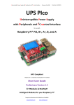
Uninterruptible Power intelligent Supply
User Manual Version 1.01
Print Date: 01.11.2013
UPiS
Uninterruptible Power intelligent Supply
for use with
RaspberryPi®
User Manual
Version 1.01
preliminary
“Raspberry Pi” is a trademark of the RaspberryPi Foundation
Firmware Release 1.00
Hardware Release VCO2
© Pi Modules
Intelligent Modules for your RaspberryPi®
Uninterruptible Power intelligent Supply
User Manual Version 1.01
Print Date: 01.11.2013
Table of Contents
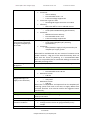
Firmware Updates Road Map ................................................................................................ 4
System Overview................................................................................................................... 5
Introduction ...................................................................................................................... 5
Applications ...................................................................................................................... 5
Features ............................................................................................................................ 5
System Basics ........................................................................................................................ 8
UPiS Versions................................................................................................................. 8
Cable Powering Sources – the Powering Feature ........................................................... 8
Battery Power Backup – the UPS feature ....................................................................... 9
UPiS Add-Ons – the Intelligent Features....................................................................... 10
System components ............................................................................................................ 11
UPiS (Basic Version) PCB View ..................................................................................... 11
UPiS (Advanced Version) PCB View .............................................................................. 13
RaspberryPi® micro USB (5 VDC) socket........................................................................ 15
Additional UPiS micro USB (5VDC) socket .................................................................... 15
Extended External Powering Input (7 VDC – 18 VDC) ................................................... 15
Onboard Rechargeable LiPO Battery (1150 mAh or 2600 mAh) .................................... 15
LiPO Battery Protection System ................................................................................... 16
Intelligent Automatic LiPO Battery Charger .................................................................. 17
Powering Modes.......................................................................................................... 17
Additional Protected 5 VDC 140 mA output for user applications................................. 23
RaspberryPi ® Hardware ON/OFF Switch ...................................................................... 23
Embedded on Board Analog Temperature Sensor accessible via RS232 interface ......... 23
Basic System Operations ..................................................................................................... 24
What is in the BOX? ..................................................................................................... 24
System Installation ...................................................................................................... 24
RaspberryPi® File Safe Shutdown Procedure and RaspberryPi® Reset............................ 29
Superior System Operations ................................................................................................ 33
UPiS Firmware Upgrade Procedure .............................................................................. 33
Routing the Serial and USB Ports ................................................................................. 39
UPiS Terminal Commands Control ............................................................................... 42
UPiS Terminal Commands Set ...................................................................................... 45
© Pi Modules
Intelligent Modules for your RaspberryPi®
Uninterruptible Power intelligent Supply
User Manual Version 1.01
Print Date: 01.11.2013
APPENDIX B
Table of LED Indications............................................................................... 54
APPENDIX C
Technical Specifications ............................................................................... 56
© Pi Modules
Intelligent Modules for your RaspberryPi®
Uninterruptible Power intelligent Supply
User Manual Version 1.01
Print Date: 01.11.2013
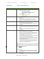
Firmware Updates Road Map
The UPiS is a hardware platform that covers many features. Most of them are supported by
the Firmware Version Release 1.00. However some of them are planned features, and are
still under testing or under development phase and will be released soon in the next
versions of firmware. The following table describes the Implementation and Versions
Release Road Map.
Firmware
Version
1.00
1.10
Features Added
UPiS Official Firmware Version Release
1. USB – RS232 interface bridge option (powering matters)
1.20
1. Original micro USB RaspberryPi® powering (the RPI mode)
full implementation
2. Onboard ESD Protected I/O pin, controlled via RS232
3. Low Powering Mode when cabling supply is available
1.30
1. Extended Tiny Encryption Algorithm (XTEA) cryptographic
Customer Software Protection System (with custom defined
protection keys)
2. RTC based Alarms for RaspberryPi® wake-up and sleep
1.40
3. Event Driven Advanced Scripting Language
© Pi Modules
Intelligent Modules for your RaspberryPi®
Uninterruptible Power intelligent Supply
User Manual Version 1.01
Print Date: 01.11.2013
System Overview
Introduction
The UPiS is an Advanced Powering add-on Module for the RaspberryPi® that adds to the
powering functionality a wealth of additional features. It is equipped with a LiPo battery
(1150 or 2600 mAh) and features a buck/boost switching power converter. There is no need
for any additional cabling or Power Supply, as the UPiS is powered by the same Power
Supply of your original RaspberryPi®; you just insert the UPiS on the top of the P1 connector
of your RaspberryPi®. The UPiS has an embedded measurement system that continuously
checks the powering voltage and current consumption, and when the cable power is absent
or insufficient, it automatically switches to the battery source. Then it keeps checking the
input voltage on all power sources, and when cable power gets available again, it switches to
it automatically, turning the battery source off. The UPiS uses exactly the same micro USB
Power Supply that you are using to supply your RaspberryPi®, however it has also an
Extended External Voltage input1 for other non-standard powering sources.
Applications
The UPiS as an add-on Module is addressed to all users that need a power back-up and/or
sensing features for applications running on the RaspberryPi®. All applications running on
the RaspberryPi® can take advantage of the uninterruptible power supply feature of the UPiS
(ranging from RaspberryPi®-based fan less servers to solar-powered applications), but in
addition the UPiS provides a wealth of sensors and features, all cumulated in a single all-inone unit, that can enable writing many innovative applications.
Features
The features of the UPiS Module can be categorized as follows:
◦
◦
◦
◦
◦
◦
Powering functionalities,
I/O and control functionalities,
RTC functionalities,
Interfaces functionalities,
Software Protection functionalities,
Environment supervising functionalities.
In detail the list of UPiS features is here below:
4. Supervised and Protected Powering from all cable sources
RaspberryPi ® micro USB (5 VDC) – available from firmware release
V1.20
1
the Extended External Voltage input is available only in the Advanced version of the UPiS
© Pi Modules
Intelligent Modules for your RaspberryPi®
Uninterruptible Power intelligent Supply
User Manual Version 1.01
Print Date: 01.11.2013
5.
6.
7.
8.
9.
10.
11.
12.
13.
14.
15.
16.
17.
18.
19.
20.
21.
22.
2
Additional micro USB (5V DC)
Extended External Powering Input (7V DC – 18V DC) [Advanced version
only]
Battery Power Backup on each cable powering source (including original
RaspberryPi® micro USB – optional after firmware activation) – the UPS feature
Onboard Rechargeable LiPO Battery (1150/2600 mAh) – battery working time is
about 2 or 5 hours, but depending from the version, system load and configuration
Onboard enhanced multiple level protection system for the LiPO battery:
Cut-off jumper
PTC fuse
Onboard Thermometer
Over-charge and Over-discharge protection
Over-voltage and Under-voltage protection
Onboard Intelligent Automatic LiPO Battery Charger (Charges the battery
automatically but only if the supply voltage is present and can provide enough
current to feed the RaspberryPi® and to charge the battery)
RaspberryPi® Hardware ON/OFF Switch
Embedded Emulated RTC (Real Time Clock – DS1307) accessible via RaspberryPi®
I2C and/or RS232 provided from the System
Onboard Analog Thermometer (accessible via RaspberryPi® RS232)
Onboard True USB interface (can be used as RS232 – USB Bridge)
Programmable Time, RaspberryPi® File Safe Shutdown Button 2
Full monitoring of all UPiS Powering Parameters via RaspberryPi® RS232 port:
Current Consumption
Voltage on each Power source
System Temperature
Battery Level
Powering source
RTC based programmed Startup/Shutdown
Onboard UPiS Reset Button (resets UPiS and RaspberryPi® but not RTC by cutting
the powering of the RaspberryPi® for a very short time)
Onboard NO RELAY controlled via RS232 or RaspberryPi® Pin (selectable by jumper
GPIO_GEN0)
Onboard ESD Protected 1-wire interface, controlled via RS232 or RaspberryPi® Pin
(selectable by jumper GPIO_GEN3) with separate 3.3V supply pull-up resistor.
Onboard ESD Protected I/O pin, controlled via RS232 or RaspberryPi® Pin (selectable
by jumper GPIO_GEN3)
Onboard True 12 V RS232 interface to the external world (with level converter)
Protected (Resettable fuse 140 mA) 5 VDC output for user applications, with battery
backup feature
Non-protected 3.3 VDC output for user applications (usually used for 1-wire
application), separate and independent from the RaspberryPi® 3.3 supply.
requires that the RaspberryPi® be powered from the second micro USB placed on the UPiS board
or from Extended External Powering Input
© Pi Modules
Intelligent Modules for your RaspberryPi®
Uninterruptible Power intelligent Supply
User Manual Version 1.01
Print Date: 01.11.2013
23. Extended Tiny Encryption Algorithm (XTEA) cryptographic Customer Software
Protection System (with custom defined protection keys)
24. Scripting language
25. LED-based Status Information System
26. Bootloader feature for lifetime firmware update.
© Pi Modules
Intelligent Modules for your RaspberryPi®
Uninterruptible Power intelligent Supply
User Manual Version 1.01
Print Date: 01.11.2013
System Basics
UPiS Versions
The UPiS module is 100% Plug and Play: there is no need to setup anything. There is no need
to change the original RaspberryPi® micro USB Power Supply as the UPiS module uses
exactly the same cabling. You only need to plug-in the P1 on the RaspberryPi® and switch ON
the UPiS module in order to supply your system. To take advantage of all the features of the
UPiS, you will typically connect the original RaspberryPi® micro USB Power Supply to the
UPiS (thus interposing the UPiS between the power supply and the RaspberryPi®), but if you
need to keep the old cabling as it was you can even select to keep the power supply directly
connected to the RaspberryPi®.
There are two versions of UPiS available: UPiS Basic and UPiS Advanced. Each one could be
ordered in two variants, i.e. with top end or stack P1 connector. The stack version allows
plugging on additional user boards, while the top end should be the end of the RaspberryPi®
System.
Cable Powering Sources – the Powering Feature
The UPiS module is designed to offer automatic power battery back-up to the RaspberryPi®
supplied from the following Cable Powering Sources:
o
o
o
RaspberryPi ® micro USB (5V DC) – available from firmware release V1.20
Additional micro USB (5V DC)
Extended External Powering Input (7V DC – 18V DC) [Advanced version only]
It is recommended to use only one Cable Powering Source at a time, however if more than
one of the Cable Powering Sources are available (plug-in) then the UPiS runs an automatic
process which selects and activates only one. The powering source selection is done
according to implemented priority algorithm. The highest priority has the RaspberryPi®
original micro USB supply, so if you fit the Cable Power Supply to the RaspberryPi® all other
sources will be automatic deselected (internally disconnected) even if you have plug in
cables to them. The next priority is the Extended External Powering Input and same as
before if you have connected this powering source the UPiS micro USB will be not active as a
power source, it will be only active as a data connection. And finally the smallest priority has
the UPiS micro USB powering. Only if all of these cable powering sources are missing the
battery back-up is activated and supplying the RaspberryPi®. In practice, because we usual
using only one cable power supply (recommended), we are just using the selected cable
power source, and when power is down, then immediately battery back-up is starting up.
Summary of power source priorities:
RaspberryPi® micro USB Extended External Powering UPiS micro USB Battery Back-up
© Pi Modules
Intelligent Modules for your RaspberryPi®
Uninterruptible Power intelligent Supply
User Manual Version 1.01
Print Date: 01.11.2013
Battery Power Backup – the UPS feature
The UPiS is an off-line UPS with extremely fast switching time and intermediate power
preservation (in fact it is line-interactive UPS). Decision when battery back-up should be
activated is made according of the powering status of the 5V Pin on the P1 connector and
current consumption.
The system continuously monitors the RaspberryPi® P1 5V Pin, detects the falling edge of
power or lower voltage than the defined threshold and within 360 us it automatically
activates the battery back-up powering, thus preventing the Raspberry Pi® from suffering an
unexpected power shutdown.
The activation time of battery back-up power is extremely fast and is executed within 120 us
and switching of power backup takes less than 14 us. In addition a large tantalum capacitor
is supplying the RaspberryPi® system during this off-line time, in order to avoid power
glitches.
Figure 1 Battery Powering switching process after a Cable Power loss
© Pi Modules
Intelligent Modules for your RaspberryPi®
Uninterruptible Power intelligent Supply
User Manual Version 1.01
Print Date: 01.11.2013
UPiS Add-Ons – the Intelligent Features
The UPiS module first of all, is an Advanced Powering System with battery back-up for the
RaspberryPi®. It is practically covering most of the possible requirements that user of the
RaspberryPi® can have with their system powering. But there's much more than this!
Following the main goal of our company “Intelligent Modules for your RaspberryPi®”, we
tried to design an as most as possible compact device, yet offering as many as possible
features for the standard user of the RaspberryPi®. We tried to design an All-in-One device
with Plug & Play capability. In fact, you do not need to set anything in order to use the UPiS
module, just Plug it on the P1 connector and Play with it! However, if you need more
features, you can easily access them by jumpers, adjusting the UPiS exactly to your current
project requirements.
The UPiS supports the user with a high number of features in a single low cost module. All of
these features will be explained in detail in the following sections.
All of these features will be explained in detail in the following sections.
© Pi Modules
Intelligent Modules for your RaspberryPi®
Uninterruptible Power intelligent Supply
User Manual Version 1.01
System components
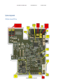
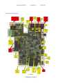
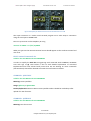
UPiS (Basic Version) PCB View
© Pi Modules
Intelligent Modules for your RaspberryPi®
Print Date: 01.11.2013
Uninterruptible Power intelligent Supply
User Manual Version 1.01
© Pi Modules
Intelligent Modules for your RaspberryPi®
Print Date: 01.11.2013
Uninterruptible Power intelligent Supply
User Manual Version 1.01
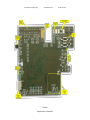
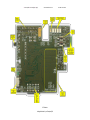
UPiS (Advanced Version) PCB View
© Pi Modules
Intelligent Modules for your RaspberryPi®
Print Date: 01.11.2013
Uninterruptible Power intelligent Supply
User Manual Version 1.01
© Pi Modules
Intelligent Modules for your RaspberryPi®
Print Date: 01.11.2013
Uninterruptible Power intelligent Supply
User Manual Version 1.01
Print Date: 01.11.2013
RaspberryPi® micro USB (5 VDC) socket
Valid for the UPiS BASIC and UPiS ADVANCED
The external power supply can be connected directly to this input of the RaspberryPi® board,
and the UPiS will still provide battery back-up to the RaspberryPi®. If the external power
supply is connected directly to the RaspberryPi®, then the UPiS will use the P1 connector
both to monitor the powering status and to inject power into the RaspberryPi® when the
sensed powering becomes insufficient. However, in this arrangement some functionality of
the UPiS is not available for it. In particular:
The hardware switch has no effect
All timed ON/OFF functionalities are not available
The measurement of current consumption cannot be performed, so the
functionalities that depend on it are not available in this powering option
Low Powering Mode for the RaspberryPi® is not available.
Therefore, to take full advantage of the UPiS functionalities, it is recommended to use this
powering input mode only if necessary.
Additional UPiS micro USB (5VDC) socket
Valid for the UPiS BASIC and UPiS ADVANCED
This Cable Powering Source is identical to the original RaspberryPi® micro USB and is
protected in the same way (with SMB 5V and 1.25 PTC resettable fuse). If the external power
supply of the RaspberryPi® is connected to this input of the UPiS, then the UPiS will feed the
RaspberryPi® through the P1 connector.
All the features of the UPiS can be exploited when using this connection scheme, therefore
it is strongly recommended to use this connection scheme.
Extended External Powering Input (7 VDC – 18 VDC)
Valid for the UPiS ADVANCED only
This Cable Powering Source is designed to support outside word of RaspberryPi® application.
Trough this Cable Powering Source it can be supplied with power from 7 V DC up to 18 VDC.
It equipped with enhanced protection system which contains: reverse polarity protection,
overvoltage protection as also PTC resettable fuse of 1.25 A. A dedicated switching converter
converts the incoming power to 5 V DC, The maximum current of the 1.4 A, however to
safety reasons, the current monitoring system allows to draw continuously only 850 mA
from it. It is ideal for car application, solar applications and basically whenever stable power
supply is not available.
Onboard Rechargeable LiPO Battery (1150 mAh or 2600 mAh)
Valid for the UPiS BASIC and UPiS ADVANCED
© Pi Modules
Intelligent Modules for your RaspberryPi®
Uninterruptible Power intelligent Supply
User Manual Version 1.01
Print Date: 01.11.2013
The UPiS is equipped with a LiPO battery. It is the power source when cable powering is
missing. There are two type of batteries offered depending of version of the UPiS. The UPiS
Basic LiPO Battery capacity is 1150 mAh, and for the UPiS Advanced LiPO Battery capacity is
2600 mAh. The LiPO batteries have been selected as a backup power sources due to best
relation between size, weight, price, and power capacity. However a special care is needed
to avoid unexpected events like overheating, fire or even explosion. Therefore you are kindly
requested to avoid any mechanical damage of such types of batteries like drilling, cutting or
breaking. If you recognize such type of battery damage please immediately disconnect it
from the system and put on safety place, before recycle it.
LiPO Battery Protection System
Valid for the UPiS BASIC and UPiS ADVANCED
The UPiS is equipped with series of battery protections in order to avoid any dangerous
incidents. There are:
Analog thermometer
The embedded UPiS microcontroller, based on the integrated analog
thermometer, continuously checks the UPiS-PCB-System-EnvironmentBattery temperature and whenever exceeds the 60 Celsius Degrees stop the
charging process, and if exceeds 60 Celsius Degrees initiate the UPiS
emergency shutdown procedure and File Safe RaspberryPi® System
shutdown. As the result it cut the system powering for security reasons.
PTC resettable fuse
Battery is connected to the system through a 2.6 A PTC resettable fuse.
Whenever battery current exceeds this value (during charging or powering
process) battery will be automatic cut-off from the system and will remain in
this stage until powering requirements come back to the normal conditions.
Cut-off power jumper
Battery powering of the system is going thought a cut-off jumper. In order to
have battery connected to the system it is necessary to short it with jumper.
It is strongly recommended for security reasons, to keep this jumper open
(battery disconnected) when system is transported and not human
supervised i.e. via Airplane. It is important to know that emulated RTC
(running on the microcontroller) is powered by the same battery with the
rest of the system. Therefore disconnecting of the system battery will cause
immediate lost of its settings.
Continuously current monitoring
© Pi Modules
Intelligent Modules for your RaspberryPi®
Uninterruptible Power intelligent Supply
User Manual Version 1.01
Print Date: 01.11.2013
The UPiS is equipped with embedded real-time current monitoring. Value of
current consumption is continuously monitored by the microcontroller and
whenever exceeds predefined values; initiate the File Safe RPi System
shutdown procedure. As the result it cut the system powering for security
reasons.
In addition each LiPO battery is equipped itself with protection PCB which controls the overcharge and over-discharge conditions of the battery. This circuit automatically cut-off
battery from power source when battery level is lower than 3 V during discharge and higher
than 4.2 V during charge process. This security system is implemented in order to save
battery live in addition to already existing protections embedded in the battery charger.
Intelligent Automatic LiPO Battery Charger
Valid for the UPiS BASIC and UPiS ADVANCED
UPiS has implemented an automatic charger that control the battery level and when it is
necessary charge it. When battery is full it automatically switches to trickle charging in order
to keep battery in a good conditions all the time. Trickle charging means charging a fully
charged battery under no-load at a rate equal to its self-discharge rate, thus enabling the
battery to remain at its fully charged level. It is an automatic process and user does not
need to intervene on it. The charger is intelligent and full microcontroller supervised. It is
dynamically switching ON and OFF the charging process whenever powering supply is not
able to provide enough current for the RaspberryPi® and battery charging. The integrated
battery is charged with a stable current of 212 mA.
Powering Modes
Valid for the UPiS BASIC and UPiS ADVANCED
The RaspberryPi® has various powering requirements depending to connected power source
and System Status. In example powering requirements and functionalities are different
when System is running on Battery or on USB cable powering (i.e. when system is running on
Battery (the UPS feature there is no battery charging). Therefore, in order to support it, the
UPiS follows System Power Requirements switches automatically to various powering
modes. There are 5 different powering states in the internal UPiS State Machine:
USB - USB Cable Powering
EPR - External Cable PoweRing
BAT - Battery Powering
LPR - Battery Low Powering
RPI - RPi Powering
Switching between modes is done automatically by internal UPiS state machine and depends
to various system parameters like Voltage on the P1 connector (5 V), Voltage on the cable
powering inputs (like EPR, USB), current consumption etc. Changes between various
© Pi Modules
Intelligent Modules for your RaspberryPi®
Uninterruptible Power intelligent Supply
User Manual Version 1.01
Print Date: 01.11.2013
powering states can be monitored using scripting language, giving to the user exact
information about what powering mode is currently running. However the switching
procedure between each mode is completely automatic and user do not need to do anything
in order to follow it. The powering modes information is addressed to more advanced users
who need to use this information for their dedicated application. A short description of each
powering mode as also required conditions when it switching on is described below.
USB Mode - USB Cable Powering
The USB Mode is the basic running mode of the UPiS and is used in most applications. It
happens when USB powering cable is connected to the UPiS micro USB connector and
RaspberryPi® is running drawing power from the UPiS through P1 connector. The
mechanical switch is switched ON. Absence of UPiS micro USB cable power switches
automatically the UPiS to the BAT mode when the RaspberryPi® system is running on power
drawing from the internal battery. All functionalities of the System are available and running.
EPR Mode - External Cable PoweRing
The EPR Mode is the second of cable powering mode of the UPiS and used in the most
embedded applications. This mode happens when Extended External Powering is connected
to the power (7V DC – 18V DC) and RaspberryPi® is running drawing power from the UPiS
through P1 connector. The EPR mode has absolute priority in UPiS System Powering. That
means if you have connected 2 cables the Extended External Powering Cable and the UPiS
micro USB Cable, the system will automatically select powering from the EPR, and internally
disconnect the micro USB cable from powering. Therefore the micro USB Cable will be still
connected, but will act only as a data connection if it is connected to PC. The mechanical
switch is switched ON. Absence of UPiS micro EPR cable power (and not availability of USB
cable) switches automatically the UPiS to the BAT mode when the RaspberryPi® system is
running on power drawing from the internal battery. All functionalities of the System are
available and running.
BAT Mode – BATtery Powering
The BAT Mode is UPS mode and happens when Cable Power is not available (the EPR, USB
and RPI). In that case the internal switching regulator, produce the necessary power from
integrated battery, and supply the RaspberryPi® with power from the UPiS through P1
connector. Switching time is extremely short (less that 14 uS within 120 uS window) and the
RaspberryPi® does not “know” that it is still powered form battery. If Cable Power returns
then the system switches back to it within 3.6 seconds. This delay in switching back to the
cable power is necessary in order to stabilize the power source. Any instability of the cable
power within this 3.6 second time cause resetting of the internal timer and counts the 3.6
seconds again until cable power will be stable for this required time. During using the
RaspberryPi® the current flow is many time high for a short times, therefore it is possible
that user will see switch to the BAT mode even if cable is still connected. It happens because
© Pi Modules
Intelligent Modules for your RaspberryPi®
Uninterruptible Power intelligent Supply
User Manual Version 1.01
Print Date: 01.11.2013
the availability of power in the PSU is not so fast as expected, which cause falling ages of
voltage, and it activates the BAT Mode in order save powering conditions of 5V on p1
connector. All functionalities (except of battery charging) of the System are available and
running.
LPR Mode – Low Powering Mode
The LPR Mode is variation of the BAT Mode and happens when the RaspberryPi® is not
drawing a power for the UPiS. Therefore the UPiS in order to save energy switch off most of
the peripherals, microcontroller and goes to sleep mode. During this more it consumes only
60 uA, and the only continuously running peripheral is the RTC. Periodically check the Cable
Powering Conditions and if it comes back switch the back to the appropriate Cable Mode.
Exceed for this mode is also possible by pressing the SHDN button, it will start up the
RaspberryPi® and switch to the BAT Mode back.
RPI Mode – RaspberryPi® Cable Powering
This is the final and used very sporadic RPI Mode. It happen only when the RaspberryPi® is
supplied from their original micro USB socked. Due to still testing of this powering mode
(especially the battery powering exit to RPI mode), it is not recommended to use it until next
version of firmware, where will be included in their full version.
© Pi Modules
Intelligent Modules for your RaspberryPi®
Uninterruptible Power intelligent Supply
Powering
Mode
EPR
USB
BAT
Description
External Cable
Powering
USB Cable
Powering
Battery Powering
User Manual Version 1.01
Print Date: 01.11.2013
Functionalities
LED Indications
EPR Input:
USB Input:
RPi USB Input:
RPi Powering:
RPi Switch:
Battery:
5VDC Output:
Analog Temp:
1-wire:
12 V RS-232:
USB interface:
Relay:
RTC:
System Monitoring:
Script Machine:
Connected
Disconnected (or only data)
Disconnected
Powered
ON
Auto/Intelligent Charging if needed
ON
ON
ON if connected
ON
ON (Jumpers depending)
ON/OFF
ON
ON
ON
USB:
EXT:
BAT:
CHG:
STA:
EPR Input:
USB Input:
RPi USB Input:
RPi Powering:
RPi Switch:
Battery:
5VDC Output:
Analog Temp:
1-wire:
12 V RS-232:
USB interface:
Relay:
RTC:
System Monitoring:
Script Machine:
Disconnected
Connected
Disconnected
Powered
ON
Auto/Intelligent Charging if needed
ON
ON
ON if connected
ON
ON
ON/OFF
ON
ON
ON
USB:
EXT:
BAT:
CHG:
STA:
EPR Input:
USB Input:
Disconnected
Disconnected
USB:
EXT:
STB:
STB:
© Pi Modules
Intelligent Modules for your RaspberryPi®
Not Light/Light only if cable connected for data
Light
Light
Not Light/Light only when battery is charging
Blinking for 100 mS every 500 mS when cable power is
connected
Not Light (Light for 800 mS every 1 s within 40 s time frame
when system is in File Safe Shutdown Procedure)
Light
Not Light
Light
Not Light/Light only when battery is charging
Blinking for 100 mS every 500 mS when cable power is
connected
Not Light (Light for 800 mS every 1 s within 40 s time frame
when system is in File Safe Shutdown Procedure)
Not Light
Not Light
Uninterruptible Power intelligent Supply
LPR
RPI
Low Powering
RPi Powering
User Manual Version 1.01
Print Date: 01.11.2013
RPi USB Input:
RPi Powering:
RPi Switch:
Battery:
5VDC Output:
Analog Temp:
1-wire:
12 V RS-232:
USB interface:
Relay:
RTC:
System Monitoring:
Script Machine:
Disconnected
Powered
ON
Not charged
ON
ON
ON if connected
ON
ON
ON/OFF
ON
ON
ON
BAT:
CHG:
STA:
EPR Input:
USB Input:
RPi USB Input:
RPi Powering:
RPi Switch:
Battery:
5VDC Output:
Analog Temp:
1-wire:
12 V RS-232:
USB interface:
Relay:
RTC:
System Monitoring:
Script Machine:
Disconnected
Disconnected
Disconnected
Not Powered
OFF/ON and SHDW
Not charged
OFF
OFF/ON periodically (every LPRSTA)
OFF
OFF
OFF
OFF
ON
OFF/ON periodically (every LPRSTA)
OFF
USB:
EXT:
BAT:
CHG:
STA:
Not Light
Light
Not Light/Light periodically (every LPRSTA)
Light only when battery is charging
Not Light
STB:
Not Light
EPR Input:
USB Input:
RPi USB Input:
RPi Powering:
RPi Switch:
Battery:
5VDC Output:
Disconnected
Disconnected
Disconnected
ON
ON
Auto/Intelligent Charging if needed
ON
USB:
EXT:
BAT:
CHG:
STA:
Light
Not Light
Light
Not Light/Light only when battery is charging
Blinking for 100 mS every 500 mS when cable power is
connected
Not Light (Light for 800 mS every 1 s within 40 s time frame
STB:
STB:
© Pi Modules
Intelligent Modules for your RaspberryPi®
Light
Not Light
Blinking for 100 mS every 500 mS when cable power is
connected
Not Light (Light for 800 mS every 1 s within 40 s time frame
when system is in File Safe Shutdown Procedure)
Light for 100 mS every 1000 mS when UPiS is running on battery
backup power and battery level is higher than 3.4V and lower
than 3.6V
Light for 100 mS every 500 mS when UPiS Advanced is running
on battery backup power and battery level is lower than 3.4V
and higher than 3.2V
Uninterruptible Power intelligent Supply
Analog Temp:
1-wire:
12 V RS-232:
USB interface:
Relay:
RTC:
System Monitoring:
Script Machine:
User Manual Version 1.01
ON
ON if connected
ON
ON
ON/OFF
ON
ON
ON
© Pi Modules
Intelligent Modules for your RaspberryPi®
Print Date: 01.11.2013
when system is in File Safe Shutdown Procedure)
THE RPI MODE IS NOT FULLY IMPLEMENTED YET
WILL BE AVAILABLE IN NEXT FIRMWARE UPDATES
Uninterruptible Power intelligent Supply
User Manual Version 1.01
Print Date: 01.11.2013
Additional Protected 5 VDC 140 mA output for user applications
Valid for the UPiS ADVANCED only
The RaspberryPi® can be used for an extremely wide range of applications. Many of them
are using additional components that require powering. In order to support these range of
application the UPiS offering a protected with PTC resettable fuse power output of 5 VDC.
This output is normally battery backup as the whole system.
RaspberryPi ® Hardware ON/OFF Switch
Valid for the UPiS BASIC and UPiS ADVANCED
The RaspberryPi® Computer is a genius system. However due to cost reason some
components are missing. One of them is the ON/OFF switch. Users sometimes like to switch
their computer ON or OFF rather than unplugging the cable. In order to overcome this
dysfunction the UPiS offer a hardware switch that completely isolates the powering from the
RaspberryPi®. This functionality is available only when powering is going through the UPiS
(the micro USB or the Extended External Power). It is not available if you are powering your
RaspberryPi® from the original micro USB placed in the computer board.
Embedded on Board Analog Temperature Sensor accessible via RS232 interface
Valid for the UPiS BASIC and UPiS ADVANCED
The RaspberryPi® ICs as also UPiS are generating a heating by itself. It is important to the
user to know at any time what temperature have the system and if is too high, take an
action (i.e. switch off or start fan with embedded Relay). For that reason a simple analog
thermometer has been implemented on the UPiS board. The value of the temperature can
be read via RaspberryPi® RS232 port. The usage of it will be explained later, on this
document. However it is very important to notice that a possibility to setup trigger on
temperature is possible and make the activity on high or low temperature automatic and
independent of the RaspberryPi®. For security reason the temperature of the UPiS cannot
exceed the 60 Celsius due to battery life cycle. Therefore if temperature is higher than 60
Celsius the UPiS as the first step of protection stop the charging of the battery in order to
reduce current consumption and if the temperature is still too high, start emergency
shutdown procedure in order to save battery and after 40 seconds stop the powering to the
RaspberryPi®.
© Pi Modules
Intelligent Modules for your RaspberryPi®
Uninterruptible Power intelligent Supply
User Manual Version 1.01
Print Date: 01.11.2013
Basic System Operations
What is in the BOX?
Valid for the UPiS BASIC and UPiS ADVANCED
This package comes with everything you need to start using right out of the box the UPiS. It
is assembled tested and consists all required accessories. A little work is necessary in order
to setup the complete RaspberryPi® and UPiS in a single full operating system.
Each Box contains the following parts:
The UPiS module assembled and tested
A stick on the UPiS bottom side of battery, dual layer wide temperature adhesive
tape (used for battery mounting)
Set of necessary jumpers (yellow)
Separate packed LiPO battery (1150 mAh for the UPiS Basic, and 2600 mAh for the
UPiS Advanced)
A male green connector used for the External Extended Powering – only for the UPiS
Advanced
A spare 1 Yellow Jumper
Please kindly notice that due to shipping regulations, LiPO batteries are packed in the same
box but are physically separated and not connected to the UPiS module. It must be
connected by the user, and it is a part of the installation procedure. Please also kindly notice
that in order to increase the safety of usage of the UPiS module all sources of the
unprotected power (mainly the enter point of the LiPO battery, and Extended External
Power input voltage – 18VDC) are covered by a special isolation in order to avoid any
damages of the device due to shortcuts made by improper use.
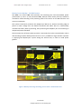
PICTURE
System Installation
Valid for the UPiS BASIC and UPiS ADVANCED
The installation procedure of the UPiS Modules is divided into the following phases:
The Battery assembly with the UPiS Modules
UPiS Module Jumpers check and setup (optional)
Physical installation of the RaspberryPi®
RaspberryPi® Software setup (optional)
Battery Assembly
Valid for the UPiS BASIC and UPiS ADVANCED
© Pi Modules
Intelligent Modules for your RaspberryPi®
Uninterruptible Power intelligent Supply
User Manual Version 1.01
Print Date: 01.11.2013
In order to install LiPo battery, you need to unpack it and connect the battery connector to
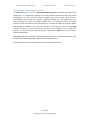
the white connector on the PCB as shown on the picture.
PICTURE
In addition the battery cable should be conducted through the slot on the UPiS Modules
PCB. Then protection from the wide temperature adhesive tape should be removed and
battery should be glued on it. The following pictures show step by step above procedure.
PICTURE
UPiS Module Jumpers setup
Valid for the UPiS BASIC and UPiS ADVANCED
The UPiS module uses interfaces with the RaspberryPi® only via 2 pins trough the P1
connector:
5V DC
GND
All other pins are free to use and depending to the user needs. Selection of which pins are
used is made using jumpers that connect UPiS selected add-ons peripherals to RaspberryPi®.
Each peripheral can be controlled via selected jumper connecting it to the RaspberryPi® or
via UPiS serial port using proper commands from a terminal program running on the
RaspberryPi® or any other computer connected to the UPiS. Selection how the required UPiS
Peripheral will be used is always made by a proper jumper set-up. The peripherals controlled
by activated by Jumpers are listed here below:
UPiS Serial Ports Switching Matrix
Valid for the UPiS BASIC and UPiS ADVANCED
The system which is folded from the RaspberryPi® and the UPiS use for communication with
external world and between them serial interfaces. There are:
o
o
o
o
RaspberryPi® Serial Port
UPiS Serial Port
UPiS micro USB port
UPiS RS232 Level Converter
Cross connectivity between them is extremely important in order to support to the user the
best possible exploitation.
In order to achieve this goal there ware designed a Serial Ports Switching Matrix based on a
jumper selection. A detailed description is provided below in a proper section below.
© Pi Modules
Intelligent Modules for your RaspberryPi®
Uninterruptible Power intelligent Supply
User Manual Version 1.01
Print Date: 01.11.2013
UPiS NO Relay Controls
Valid for the UPiS ADVANCED only
The UPiS Advanced offers a single low power Normally Open Relay. The outputs of its pins
are placed on the screws free I/O 8 Pins Terminal: RA and RB. It is shown here below.
Figure 6 Top View - Screws free I/O 8 Pins Terminal
This NO Relay can be controlled by the UPiS commands through the terminal program or
directly by the RaspberryPi® from a dedicated Pin GPIO_GEN0 (P1 Connector PIN 11).
Selection what controls over the NO Relay is done via selection with a Jumper S3 as shown
on the picture here below.
Figure 7 S3 Top and Bottom View – UPiS Control Selected
In a case that RaspberryPi® has been selected to control the NO Relay it is a user
responsibility to write an appropriate script or program handling this Pin. In a case that UPiS
© Pi Modules
Intelligent Modules for your RaspberryPi®
Uninterruptible Power intelligent Supply
User Manual Version 1.01
Print Date: 01.11.2013
has been selected to control the NO Relay, it can be done via terminal from the RaspberryPi®
or PC or any other application accessing the Serial Port on the RaspberryPi®. The appropriate
commands to do it are:
@RON – Relay ON (Close)
@ROFF – Relay OFF (Open)
Battery cut-off jumper
Valid for the UPiS BASIC and UPiS ADVANCED
The integrated battery is equipped with a various security protections. One of them is the
cut-off jumper – P4. The usage of this jumper is to galvanic isolate the battery from the UPiS
system. There is important to note that by removing this jumper, battery is not charged, and
the UPiS system is not supplying including RTC. Therefore opening of it is necessary only
when UPiS is shipped via Air Plane for security reasons. For normal usage of the UPiS this
jumper should be always closed.
Figure 8 Bottom View Battery Cut-Off Jumper
1-wire selection Jumper
Valid for the UPiS ADVANCED only
The UPiS Advanced has an embedded interface for the 1-wire® sensors. This interface is ESD
protected. This 1-wire interface can be controlled by the UPiS commands through the
Terminal Program or directly by the RaspberryPi® from a dedicated Pin GPIO_GEN3 (P1
Connector PIN 15). Selection what controls over the 1-wire is done via selection with a
Jumper S2 as shown on the picture here below.
© Pi Modules
Intelligent Modules for your RaspberryPi®
Uninterruptible Power intelligent Supply
User Manual Version 1.01
Print Date: 01.11.2013
Figure 9 S2 Top and Bottom View – UPiS Control Selected
In a case that UPiS has been selected to control the 1-wire® interface, it can be done via
terminal from the RaspberryPi® or PC or any other application accessing the Serial Port on
the RaspberryPi®. The appropriate commands to do it are:
@1WIREC - 1-wire® Temperature Celsius
@1WIREF - 1-wire® Temperature Fahrenheit
In the future release of firmware our company is planning to release commands for the ibutton® security key.
I2C Connection Jumpers (RTC)
Valid for the UPiS BASIC and UPiS ADVANCED
The UPiS is equipped with RTC which is supplied by the same battery with the rest of the
system. The RTC is a software emulated DS1307. It communicates with the RaspberryPi®
identical with the original DS1307. In order to have connectivity with the RTC user need to
short 2 jumpers of the I2C (the SDA and SDL). A detailed description how to use and set-up
the UPiS RTC is described in another part. Here below is shown the connected I2C to the
RaspberryPi®. If user use another application where these pins are needed should left them
free. Please kindly notice that it is possible to use multiple I2C devices on the same bus.
Figure 10 Bottom View - I2C connected to the RaspberryPi
© Pi Modules
Intelligent Modules for your RaspberryPi®
Uninterruptible Power intelligent Supply
User Manual Version 1.01
Print Date: 01.11.2013
File Safe Shutdown initiation Pin Jumper
Valid for the UPiS BASIC and UPiS ADVANCED
The File Safe Shutdown feature gives to the user a proper way to shutdown the RaspberryPi®
by a single button pressing. However this procedure need to be recognized by the
RaspberryPi® and for that reason a dedicated jumper need to be closed (set). If it will be
open then the RaspberryPi® will never know that somebody request the shutdown of the
system. The detailed procedure of the setting-up shutdown is described here below.
Figure 11 Bottom View the File Safe Shutdown Jumper
RaspberryPi® File Safe Shutdown Procedure and RaspberryPi® Reset
Valid for the UPiS BASIC and UPiS ADVANCED
In order to support the File Safe Shutdown procedure a simple script should be written and
stored on the RaspberryPi®. There are many simple script written around this matter and
can be easy find out over the internet, however we provide one examples that could be easy
implement. Scripts could be divided into two basic categories:
Interrupt based and
Loop based.
User of the UPiS module is basically free to use their own script, however always should
keep in mind some basics of the implemented circuit on the UPiS board:
There are no Pull-Up resistors on the UPiS board therefore user need to setup the
RaspberryPi® resistors
The Pin which has been dedicated to this task is the pin GPIO.27
Before this functionality will be used user need to put a proper jumper on the UPiS
Board otherwise it will be not working as the input pin GPIO.27 is continuously
scanning it to see if low state is.
© Pi Modules
Intelligent Modules for your RaspberryPi®
Uninterruptible Power intelligent Supply
User Manual Version 1.01
Print Date: 01.11.2013
If user does not need this functionality or need this pin, the pin GPIO.27 could be
used for other applications; the associated jumper should be open (removed).
There are two basic functionalities associated with the Shutdown Button. There are:
Reset Functionality
File Safe Shutdown (if a proper script is applied to the RaspberryPi®)
Figure 12 Top View SDWN and RST Buttons
The Reset Functionality, is executed when the Shutdown Button is pressed for a longer time
than 0.3 second and shorter than 2 second. In practice, it means that user need to press the
button, little bit longer and then leaves it up. Then the UPiS module will cut immediately
power of the RaspberryPi® for a 1 second and then power it again. This cutting of power is
like a rest and immediately stops all functionalities of the RaspberryPi®.
Please kindly notice that using of this functionality can cause of file system destroy in the SD
card, therefore it is STRONGLY RECOMMENDED to use it ONLY if the RaspberryPi® does not
response to any input device.
The File Safe Shutdown Functionality does not have this limitation, and safe files from any
corruption. It is executed when the Shutdown Button is pressed for a longer time than 2
seconds. In order to simplify usage of it, when UPiS Module recognize pressed button for the
File Safe Shutdown lights the RED led for 1 second, and then flash it every second for 800
ms. In practice, it means that user need to press the button until RED led light and release it
just after that. Following will see the flashing RED led. This is optical information that File
Safe Shutting down procedure has been initiated and is in progress. It takes 40 seconds (on
the UPiS module), and after that you will see that RaspberryPi® has been stop. If you have
initiated terminal on the RaspberryPi® or connected other computer via USB you will see
also the following messages on the screen.
UPiS System Stared File Safe Shutdown Procedure
And when finished the shutting down
© Pi Modules
Intelligent Modules for your RaspberryPi®
Uninterruptible Power intelligent Supply
User Manual Version 1.01
Print Date: 01.11.2013
UPiS System Finished File Safe Shutdown Procedure
Here below is described the simple procedure how to implement the simplest Python script
used for the Safe File Shutdown.
Open Terminal from the command line or open an LXTerminal session, and use the Nano
text editor to add some code to enable the Python script created to run when the
RaspberryPi® boots up. Type in:
sudo nano /etc/rc.local
and then add in the following code:
sudo python /home/pi/upis/fshut.py
before the line that says:
exit 0
Press Ctrl+X to exit the Nano editor and when prompted press Y and then Enter in order to
save the file you just edited.
Next prepare the directory where the script will be place i.e. “upis” using the following
command:
mkdir upis
Using nano editor write the following script and save on pre-prepared directory “upis” with a
name fshut.py
sudo nano /home/pi/upis/fshut.py
The screen below shows the script that need to be entered using nano.
© Pi Modules
Intelligent Modules for your RaspberryPi®
Uninterruptible Power intelligent Supply
User Manual Version 1.01
Print Date: 01.11.2013
Figure 13 File Safe Shutdown Python Script - fshut.py
# Import the libraries to use time delays, send os commands and access GPIO pins
import RPi.GPIO as GPIO
import time
import os
GPIO.setmode(GPIO.BCM) # Set pin numbering to board numbering
GPIO.setup(27, GPIO.IN, pull_up_down=GPIO.PUD_UP) # Setup pin 27 as an input
while True: # Setup a while loop to wait for a button press
if(GPIO.input(27)==0): # Setup an if loop to run a shutdown command when button press sensed
os.system("sudo shutdown -h now") # Send shutdown command to os
break
time.sleep(1) # Allow a sleep time of 1 second to reduce CPU usage
You can easy check if your script is running just writing on the command line
sudo python /home/pi/upis/fshut.py
and then pressing the Shutdown Button for more than 2 seconds (until RED led will light on).
If you are done properly your above tasks, the computer should print on the screen the
following message and shutdown then.
The system is going down for system halt NOW!
After the Safe File Shutdown you can restart your RaspberryPi® using the Reset
Functionality. This is the proper way of restarting you computer when using the UPiS
module, because removing cable activated battery back-up, and do not stop the system.
After shutdown of the RaspberryPi® it is recommended to switch off the computer using the
hardware switch placed on the UPiS PCB. If the system is supplied from battery power back© Pi Modules
Intelligent Modules for your RaspberryPi®
Uninterruptible Power intelligent Supply
User Manual Version 1.01
Print Date: 01.11.2013
up then it will goes automatically to Low Power Mode. This functionality will be also
available for the Cable Powering in future Firmware Updates.
Therefore there are the following ways to switch of the RaspberryPi®:
1. Safe File Shutdown (without risk of corrupted files)
2. Switch Off the system with the integrated mechanical switch (with a risk
of files corruption)
Superior System Operations
UPiS Firmware Upgrade Procedure
Valid for the UPiS BASIC and UPiS ADVANCED
In order to keep UPiS module firmware up-to-date an embedded serial bootloader has been
implemented. Invoking it is done when the UPiS module starts from UPiS RESET with pressed
at the same time SHDN button. This feature allows user to update the firmware trough the
micro USB port placed on the UPiS module. In order to upload the new firmware to the UPiS
dedicated bootloader software needs to be running on the PC. Current version of the boot
loader supports only Windows® Operating System. For the UPiS Firmware Update Procedure
will be needed:
1. Personal Computer with Windows® OS
2. Micro USB to USB cable
3. The bootloader program. You need to download the bootloader software file
with a name UPiS_bootloader.zip from the following location:
http://www.pimodules.com/downloads/UPiS_bootloader.zip
Save to a known location on your PC and unzip it to a folder i.e. c:\UPiS\.
Unzipping of this file will generate:
i. UPiS_BL.exe
ii. UPiS_Bootloader.bat
4. The latest Hex file of the firmware. You need to download the latest UPiS
firmware file with a name UPiS_firmware_v1.00.zip from the following location:
http://www.pimodules.com/downloads/UPiS_firmware_v1.00.zip
Save to a known location on your PC and unzip it to a folder i.e. c:\UPiS\.
Unzipping of this file will generate:
i. UPiS_V1.00.hex
ii. UPiS_V1.00_recent_changes.txt
5. Any Terminal program running on the PC (i.e. TearTerm, HyperTerminal or any
other). It must be set to 38400 8N2, to make it connection with the UPiS
© Pi Modules
Intelligent Modules for your RaspberryPi®
Uninterruptible Power intelligent Supply
User Manual Version 1.01
Print Date: 01.11.2013
6. The UPiS module itself
The UPiS_BL.exe need to be call from the COMMAND PROMPT with the following
parameters:
UPiS_BL PORT=COMX BAUD=38400 UPiS_V1.00.hex
Where:
PORT=COMX is the Virtual Com Port which has been recognized by the Windows®
OS when UPiS is connected to the PC USB Port (i.e. COM1, COM2 etc).
BAUD=38400 is the data rate in which UPiS communicate with the system. Do not
change it.
UPiS_V1.00.hex is the latest firmware update file
However, because calling of this software need to be done from the COMMAND PROMPT it
can cause some troubles for none experienced users. There is another way to use of it,
probably simpler than the first one. This is by running the UPiS_Bootloader.bat. It can be
done from the graphic environment, just by clicking it. However, before do it, must be edited
with a notepad, and adopted parameters about the COM port, and probably the .HEX file.
After downloading and adopting the software, the next step is to upload the latest firmware
to the UPiS module. Here below is described step by step the firmware updating procedure:
1. Shutdown the RaspberryPi® if it is running using File Safe Shutdown Procedure
2. After that, switch OFF the powering of the RaspberryPi® with mechanical switch
of the UPiS
3. It would be also good idea to unplug completely the RaspberryPi® however it is
not necessary, and depends of the Jumper setting you have already set. If you
need to set Jumpers, it is better to unplug the RaspberryPi® from the UPiS. The
most important is to completely isolate powering of the RaspberryPi® from the
UPiS module.
4. Set the proper Jumpers in the Serial Ports Connection Matrix
5. Selected connection should be: UPiS Serial Port routed to the UPiS micro USB
Connector
© Pi Modules
Intelligent Modules for your RaspberryPi®
Uninterruptible Power intelligent Supply
User Manual Version 1.01
Print Date: 01.11.2013
6. Connect the UPiS module through their micro USB socket to USB socket in your
PC via cable
7. Be sure that UPiS is connected through their micro USB to computer and
powered via the same port
8. The UPiS micro USB should be recognized by the Windows® OS and Virtual Com
Port should be assigned. If you doing that for the first time it could take little bit
longer because Windows® OS will install automatically the required driver.
9. Using Device Manager check the Virtual Com Port number assigned to the UPiS
USB connection i.e. COM29
10. Set the following parameters on the Virtual Com Port:
Bit per Second: 38400
Data Bits: 8
Parity: NONE
Stop Bits: 2
Flow Control: XON/XOFF
In the Advanced Tab make the following changes
© Pi Modules
Intelligent Modules for your RaspberryPi®
Uninterruptible Power intelligent Supply
User Manual Version 1.01
Print Date: 01.11.2013
Latency Timer: 1
11. You should know the Virtual Com Port in order to use it with the UPiS_BL.exe
bootloader software.
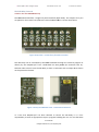
12. To invoke the bootloading procedure on the UPiS press the RST button, and
after that (having pressed the RST button) the SDWN, and after that, release the
button RST (having pressed the SDWN button), release the SDWN button. You
will have all Green LEDs light, and then (STB) RED Light. Your UPiS is now in the
bootloading mode and waiting for the hex file. This procedure can be easy done
with one finger due to close placement of these two buttons.
Figure 14 Top View Bootloader LEDs (Green and Red), SDWN and RST Buttons
13. Be sure that the Terminal program is not running because you will have a
conflict with the Virtual Com Ports when UPiS_BL.exe will be called
© Pi Modules
Intelligent Modules for your RaspberryPi®
Uninterruptible Power intelligent Supply
User Manual Version 1.01
Print Date: 01.11.2013
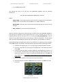
14. Run the UPiS_BL.exe with required parameters from the COMMAND PROMPT
or the modified UPiS_Bootloader.bat
15. When you start it, the (STB) RED led will be switched to (STA) Green and you will
see the following picture on the screen.
16. The Firmware uploading procedure takes about 30-40 seconds, after that UPiS
Restarts
17. It is very important after latest firmware update, with connected UPiS to your
PC, to run Terminal Program, select the proper COM port press the RST button,
see messages sent by UPiS to the Terminal and type the command @FACTORY
to set the factory defaults
18. The following picture will be visible on the terminal screen:
© Pi Modules
Intelligent Modules for your RaspberryPi®
Uninterruptible Power intelligent Supply
User Manual Version 1.01
Print Date: 01.11.2013
There is also a good idea to run the command @status in order to see the UPiS Status
© Pi Modules
Intelligent Modules for your RaspberryPi®
Uninterruptible Power intelligent Supply
User Manual Version 1.01
Print Date: 01.11.2013
After that the UPiS will be ready to use it with the RaspberryPi®.
There is only on firmware available for both types of UPiS Basic and UPiS Advanced. The
firmware automatic recognize on which type of board is running and automatically selects
the available futures.
Routing the Serial and USB Ports
Valid for the UPiS BASIC and UPiS ADVANCED
Both versions of UPiS modules are equipped with micro USB interface (for powering and for
data transfer) as also the UPiS Module Advanced is in addition equipped with RS232 Level
Converter. These interfaces are designed in a way that allows connectivity between various
serial links of the pair UPiS module and RaspberryPi®. In order to allow these various types
of connectivity a Switching Matrix has been implemented. It is a set of jumpers that with a
selectable configuration forced various connectivity schemes. There are:
© Pi Modules
Intelligent Modules for your RaspberryPi®
Uninterruptible Power intelligent Supply
User Manual Version 1.01
Print Date: 01.11.2013
1. Routes RaspberryPi® RS232 to the UPiS Module micro USB Connector
Valid for the UPiS BASIC and UPiS ADVANCED
This setting routes the RS232 RaspberryPi® RS232 to the UPiS Module micro USB
connector allowing viewing on the PC their I/O. The user can change access of this
interface in the RaspberryPi® in order to use it on their applications, but it can be
used also for Emergency Recovery of the RaspberryPi®. The proper settings of the
jumpers are shown here below. The RS232 of the RaspberryPi® is set to the 115200
bps 8N1, so terminal program on the PC should be set to the same rate and other
parameters.
Figure 15 RaspberryPi® RS232 connected to the UPiS Module micro USB
Disabling the Recovery use of the RaspberryPi® RS232 is explained in details in the
next sections and should be done if user plans to use this port for any other
application than rescue procedure.
2. Routes RaspberryPi® RS232 to RS232 UPiS Level Converter
Valid for the UPiS ADVANCED only
Similar as in the (1) the RS232 of the RaspberryPi® can be routed to the UPiS RS232
level converter instead to the UPiS micro USB interface. Usage is similar to the
described above. This functionality is available only in the UPiS Advanced.
© Pi Modules
Intelligent Modules for your RaspberryPi®
Uninterruptible Power intelligent Supply
User Manual Version 1.01
Print Date: 01.11.2013
Figure 16 RaspberryPi® RS232 connected to RS232 UPiS Level Converter
3. Route RaspberryPi® RS232 to UPiS Serial Port
Valid for the UPiS BASIC and UPiS ADVANCED
The UPiS Advanced and UPiS Basic are equipped with their own serial port. This port
is used to control the UPiS from a terminal program. There is a long list of
commands available to control the UPiS. If user like to control the UPiS from their
RaspberryPi® need to connect the UPiS serial port to the RaspberryPi® serial port. A
detailed description how to make it in the RaspberryPi® is provided in another point
of this manual. However independent from the setting on the RaspberryPi® there
must be also a physical connection between UPiS and RaspberryPi®, which must be
done by setting the proper jumpers like in the picture below.
Figure 17 RaspberryPi® RS232 connected to UPiS Serial Port
4. UPiS Serial Port to the UPiS USB Connector
Valid for the UPiS BASIC and UPiS ADVANCED
This setting is similar to the (3) however routes the UPiS serial port to the UPiS micro
USB. It is used for the firmware bootloading, for debugging purposes or just have a
control over the UPiS via terminal running on PC.
© Pi Modules
Intelligent Modules for your RaspberryPi®
Uninterruptible Power intelligent Supply
User Manual Version 1.01
Print Date: 01.11.2013
Figure 18 UPiS Serial Port connected to the UPiS USB Connector
5. RS232 Level Converter Port to the UPiS USB Connector
Valid for the UPiS ADVANCED only
The UPiS RS232 level converter and UPiS micro USB are completely independent
hardware on the board of the UPiS. Therefore it can be connected and used
according to jumper setting. Sometime there is a need to have independent USB to
Serial converter. This configuration of jumpers make exactly this thing – an
independent USB to RS232 converter that can be used in the application built based
on RaspberryPi®.
Figure 19 RS232 Level Converter Port connected to the UPiS USB Connector
UPiS Terminal Commands Control
Valid for the UPiS BASIC and UPiS ADVANCED
The UPiS is a Plug and Play device in their basic functionality. After assembly of the battery
and connection with RaspberryPi® there is no need for any additional maintenance in order
© Pi Modules
Intelligent Modules for your RaspberryPi®
Uninterruptible Power intelligent Supply
User Manual Version 1.01
Print Date: 01.11.2013
to use most of features. However there is a group of users that have more advanced needs.
The Terminal Commands Control is addressed to them. The TCC give to such user a plenty of
additional features all in a single board. Some of them can be accessed directly from the
RaspberryPi® Pins by using jumpers’ selection, but all of them can be accessed from a single
access point the RaspberryPi® RS232 port connected directly to the UPiS Serial Port. This can
be done simple by a terminal program or by software written in any language (C, Python etc)
that has an access to the RaspberryPi® Serial Port. Here below will be presented all
commands as also how to make necessary changes in the RaspberryPi® in order to use their
serial port by user application. Writing software to handle the serial port in various
languages is not a part of this manual, therefore all command will be presented how can be
handled from the terminal program.
In addition if the UPiS Serial Port will be routed to the UPiS micro USB interface this
functionality can be handle also from a PC and associated Terminal Program (i.e. TeraTerm).
Then it is not necessary to make any modifications to the RaspberryPi® Serial Port usage.
Setting Up the RaspberryPi® Serial Port
Valid for the UPiS BASIC and UPiS ADVANCED
By default the RaspberryPi®’s serial port is configured to be used for console input/output.
Whilst this is useful if you want to login using the serial port, it means you can't use the
Serial Port in your programs. To be able to use the serial port to connect and talk to other
devices the serial port console login needs to be disabled.
Needless to say you will need some other way to login to the RaspberryPi®, it is suggested
doing this over the network using an SSH connection.
Disable Serial Port Login
To enable the serial port for your own use you need to disable login on the port. There are
two files that need to be edited
The first and main one is:
/etc/inittab
This file has the command to enable the login prompt and this need to be disabled. Edit the
file and move to the end of the file. You will see a line similar to:
T0:23:respawn:/sbin/getty -L ttyAMA0 115200 vt100
Disable it by adding a # character to the beginning. Save the file.
#T0:23:respawn:/sbin/getty -L ttyAMA0 115200 vt100
© Pi Modules
Intelligent Modules for your RaspberryPi®
Uninterruptible Power intelligent Supply
User Manual Version 1.01
Print Date: 01.11.2013
Disable Bootup Info
When the RaspberryPi® boots up, all the bootup information is sent to the serial port.
Disabling this bootup information is optional and you may want to leave this enabled as it is
sometimes useful to see what is happening at bootup. If you have a device connected (i.e.
Arduino) at bootup, it will receive this information over the serial port, so it is up to you to
decide whether this is a problem or not.
You can disable it by editing the file:
/boot/cmdline.txt
The contents of the file look like this
dwc_otg.lpm_enable=0 console=ttyAMA0,115200 kgdboc=ttyAMA0,115200 console=tty1
root=/dev/mmcblk0p2 rootfstype=ext4 elevator=deadline rootwait
Remove all references to ttyAMA0 (which is the name of the serial port). The file will now
look like this:
dwc_otg.lpm_enable=0 console=tty1 root=/dev/mmcblk0p2 rootfstype=ext4
elevator=deadline rootwait
Reboot
In order you enable the changes you have made, you will need to reboot the Raspberry Pi
sudo shutdown -r now
Test the Serial Port
A great way to test out the serial port is to use the minicom program. If you don’t have this
installed run
sudo apt-get install minicom
Connect your PC to the RaspberryPi® via Virtual Serial Port using an appropriate jumpers
setting (RaspberryPi® RS232 to the UPiS Module micro USB Connector),
© Pi Modules
Intelligent Modules for your RaspberryPi®
Uninterruptible Power intelligent Supply
User Manual Version 1.01
Print Date: 01.11.2013
Figure 20 RaspberryPi® RS232 connected to the UPiS Module micro USB
then open TeraTerm or a similar serial terminal program on PC side. Setup a connection
using the serial port at 38400 baud.
Now run up minicom on the Raspberry Pi using
minicom -b 38400 -o -D /dev/ttyAMA0
What you type into the minicom terminal screen should appear on the serial PC terminal and
vice versa.
UPiS Terminal Commands Set
Valid for the UPiS BASIC and UPiS ADVANCED
In order to simplify the UPiS TCC string parsing each command send to UPiS are ALWAYES
start with sign of @. Here below is the list with detailed explanation of command
implemented until now. Please kindly notice that we are working on more commands
(functionalities) that will be released soon with the next firmware releases.
COMMAND: @FACTORY
Valid for the UPiS BASIC and UPiS ADVANCED
Meaning: Factory Defaults.
Usage: @factory or @FACTORY
Results/Explanation: Return UPiS to Factory Default Values. Should be used always after
upload of a new firmware.
COMMAND: @VERSION
Valid for the UPiS BASIC and UPiS ADVANCED
Meaning: Print the Version
© Pi Modules
Intelligent Modules for your RaspberryPi®
Uninterruptible Power intelligent Supply
User Manual Version 1.01
Print Date: 01.11.2013
Usage: @version or @VERSION
Results/Explanation: Return UPiS Hardware and Firmware Version
COMMAND: @STATUS
Valid for the UPiS BASIC and UPiS ADVANCED
Meaning: Print the UPiS Status
Usage: @status or @STATUS
Results/Explanation: Return UPiS detailed status that contains all needed parameters of the
system like: powering source, Voltages, Current, and Analog Temperature etc.
COMMAND: @RON
Valid for the UPiS ADVANCED only
Meaning: Normally Open Relay switch ON
Usage: @ron or @RON
Results/Explanation: Switch the NO Relay ON
COMMAND: @ROFF
Valid for the UPiS ADVANCED only
Meaning: Normally Open Relay switch OFF
Usage: @roff or @ROFF
Results/Explanation: Switch the NO Relay OFF
COMMAND: @ANTMPC
Valid for the UPiS BASIC and UPiS ADVANCED
Meaning: Print the UPiS Analog Thermometer Temperature
Usage: @antmpc or @ANTMPC
Results/Explanation: Return UPiS Analog Thermometer Temperature in Celsius
COMMAND: @ANTMPF
Valid for the UPiS BASIC and UPiS ADVANCED
© Pi Modules
Intelligent Modules for your RaspberryPi®
Uninterruptible Power intelligent Supply
User Manual Version 1.01
Print Date: 01.11.2013
Meaning: Print the UPiS Analog Thermometer Temperature
Usage: @antmpf or @ANTMPF
Results/Explanation: Return UPiS Analog Thermometer Temperature in Fahrenheit
COMMAND: @PM
Valid for the UPiS BASIC and UPiS ADVANCED
Meaning: Powering Mode
Usage: @pm or @PM
Results/Explanation: Return UPiS actual Powering Mode. There are:
USB - USB Cable Powering
EPR - External Cable PoweRing
BAT - Battery Powering
LPR - Battery Low Powering
RPI - RPi Powering
COMMAND: @ CHGR ON/OFF
Valid for the UPiS BASIC and UPiS ADVANCED
Meaning: Switch Automatic Intelligent Charger OFF or ON
Usage: @chgr on or @CHGR ON
Usage @chgr off or @CHGR ON
Results/Explanation: Switches the Automatic Intelligent LiPOLiPo battery Charger ON or
OFF. It is necessary sometimes when you are supplying the RaspberryPi® from a power
source with reduced current availability like user PC USB interface. Under normal conditions
UPiS check all the time system current consumption and when it is bigger than 750 mA, then
it is switching OFF the charger, but sometimes the available current is not enough and is
below it, therefore user need to close the battery charging completely. The UPS feature will
be still active even if battery is not charged.
COMMAND: @RPI
Valid for the UPiS BASIC and UPiS ADVANCED
Meaning: Voltage on the RaspberryPi® 5V P1 connector
Usage: @rpi or @RPI
© Pi Modules
Intelligent Modules for your RaspberryPi®
Uninterruptible Power intelligent Supply
User Manual Version 1.01
Print Date: 01.11.2013
Results/Explanation: Return the actual exact value of the RaspberryPi® 5V voltage P1
connector
COMMAND: @EPR
Valid for the UPiS ADVANCED only
Meaning: Voltage on the External Extended Powering connector (7 V DC – 18 V DC)
Usage: @epr or @EPR
Results: Return the actual exact value of the Voltage on the External Extended Powering
connector (7 V DC – 18 V DC)
COMMAND: @USB
Valid for the UPiS BASIC and UPiS ADVANCED
Meaning: Voltage on the UPiS micro USB connector
Usage: @usb or @USB
Results/Explanation: Return the actual exact value of the voltage on the UPiS micro USB
connector
COMMAND: @BAT
Valid for the UPiS BASIC and UPiS ADVANCED
Meaning: Voltage on the UPiS Battery
Usage: @bat or @BAT
Results/Explanation: Return the actual exact value of the voltage on the UPiS Battery
COMMAND: @CUR
Valid for the UPiS BASIC and UPiS ADVANCED
Meaning: System Current Consumption
Usage: @cur or @CUR
Results/Explanation: Return the actual exact value of the UPiS and RaspberryPi® system
current consumption
Accuracy - 10mA
The measurement contains:
© Pi Modules
Intelligent Modules for your RaspberryPi®
Uninterruptible Power intelligent Supply
User Manual Version 1.01
Print Date: 01.11.2013
The RaspberryPi® current consumption
Battery Charging current consumption
Relay ON current consumption
Microcontroller current consumption
RS232 Level Converter current consumption
Serial Bridge current consumption
UPiS LEDs current consumption
Various Components of the UPiS current consumption
There is a working version that will be released soon with a new firmware, showing
separated current consumption of the RaspberryPi® and UPiS
COMMAND: @1WIREC
Valid for the UPiS ADVANCED only
Meaning: Print the 1wire sensor Thermometer Temperature
Usage: @1wirec or @1WIREC
Results/Explanation: Return 1wire sensor Thermometer Temperature in Celsius with
accuracy of 0.1 degree in Celsius
COMMAND: @1WIREF
Valid for the UPiS ADVANCED only
Meaning: Print the 1-wire® sensor Thermometer Temperature
Usage: @1wiref or @1WIREF
Results/Explanation: Return 1-wire® sensor Thermometer Temperature in Celsius with
accuracy of 0.1 degree in Fahrenheit
COMMAND: @ PWRINFO ON/OFF
Valid for the UPiS BASIC and UPiS ADVANCED
Meaning: Set ON/OFF the Automatic Trigger when Powering Source is changing
Usage: @pwrinfo on or @PWRINFO ON
Usage: @ pwrinfo off or @ PWRINFO OFF
Results/Explanation: If set to ON every time when powering source is changed send a
message. It is very useful to know for some remote application automatically when powering
source has been changed
© Pi Modules
Intelligent Modules for your RaspberryPi®
Uninterruptible Power intelligent Supply
User Manual Version 1.01
Print Date: 01.11.2013
COMMAND: @ LPRSTA
Valid for the UPiS BASIC and UPiS ADVANCED
Meaning: Low Powering Restart Sampling Time
Usage: @lprsta <number 1-99> or @LPRSTA <number 1-99>
Usage: @lprsta or @LPRSTA
Usage: @lprsta ? or @LPRSTA ?
Results/Explanation: Return or set the Low Power Return Time.
When System of UPiS and RaspberryPi® are supplied from battery if the user shutdown it
using the File Safe Shutdown Procedure, or just switch off using mechanical switch, then
after couple of second the UPiS is going to the Low Powering Mode (sleeping mode) where
the current consumption is very small. Usual the UPiS consume during the LPR mode about
60 – 70 uA and the only running peripheral during that time is the RTC. The recovery from
this mode is possible in two ways:
By pressing the SHDN button
By switching the mechanical switch or
By entering Cable Power
However, because the UPiS is in very Low Powering Mode most of the peripherals are not
working - are sleeping and not consuming current. Therefore the UPiS needs to stand up
periodically, supply the peripherals, make some measurements in order to see what is going
on around it (i.e. if Cable Power has been entered, RaspberryPi® switched ON and
consuming current etc.). These checks of peripherals take 9 mS, and consume 300 uA. The
time how often it is done is the LPRSTA time. The default value is 5 second, and that means
that every 5 second UPiS stand-up for a 9 mS, check their peripherals, and if nothing happen,
then going to sleep again, if restart even happen (listed above) goes out from the LPR mode
and start sunning as before. Because during stand-up consumption of current is much
higher, user can adjust how often it will happen in order to safe battery (energy).
Examples:
@LPRSTA 10
(means that even if put the Cable to USB it will be recognized after
10 seconds, and then the system starts-up)
COMMAND: @TIME
Valid for the UPiS BASIC and UPiS ADVANCED
Meaning: Shows the current UPiS RTC TIME
Usage: @time or @TIME
© Pi Modules
Intelligent Modules for your RaspberryPi®
Uninterruptible Power intelligent Supply
User Manual Version 1.01
Print Date: 01.11.2013
Results/Explanation: Return the TIME of the UPiS RTC
COMMAND: @DATE
Valid for the UPiS BASIC and UPiS ADVANCED
Meaning: Shows the current UPiS RTC DATE
Usage: @date or @DATE
Results/Explanation: Return the DATE of the UPiS RTC
COMMAND: @START
Valid for the UPiS BASIC and UPiS ADVANCED
Meaning: Startup RaspberryPi® after X minutes
Usage: @start or @START
Disable the START timer procedure (reset the START timer to 0)
Usage: @start ? or @START ?
Show the set value of the START timer
Usage: @start ! or @START !
Show the current value of the running START timer. This timer is decreasing until reaches
value of 0 and then startup the RaspberryPi®
Usage: @start <number> or @START <number>
Set the current value of the START timer. The <number> must be from 2 up to 1000 minutes
Results/Explanation:
A detailed explanation is in here below together with the @STOP command
COMMAND: @STOP
Valid for the UPiS BASIC and UPiS ADVANCED
Meaning: Shutdown RaspberryPi® after X minutes
Usage: @stop or @STOP
Disable the STOP timer procedure (reset the STOP timer to 0)
Usage: @stop ? or @STOP ?
© Pi Modules
Intelligent Modules for your RaspberryPi®
Uninterruptible Power intelligent Supply
User Manual Version 1.01
Print Date: 01.11.2013
Show the set value of the STOP timer
Usage: @stop ! or @STOP !
Show the current value of the running STOP timer. This timer is decreasing until reaches
value of 0 and then shutdown using File Safe Shutdown Procedure the RaspberryPi®
Usage: @stop <number> or @STOP <number>
Set the current value of the STOP timer. The <number> must be from 2 up to 1000 minutes
Results/Explanation:
There are many applications especially when running the RaspberryPi® on battery supply
when user needs to start it for a short time do something; and then after predefined time
shutdown it. This approach is ideal when power is not enough, therefore stopping and
running the RaspberryPi® save a lot of energy.
The START and STOP command predefine two timers that counts running and sleeping time.
Each timer starts when the other is stopped. IN order to have running this system both
values START and STOP should be set. The UPiS executes always first the STOP after X
minutes command. Both values are stored in the UPiS EEPROM, therefore it wills run as far
the system is connected to the RaspberryPi®.
Examples:
@START 5
(means sleep for 5 minutes and then startup)
@STOP 3
(means run for 3 minutes and then shutdown)
Means that system will shut down after 3 minutes then will be sleeping for 5 minutes and
then start up and running for 3 minutes, then shutdown and sleeping for 5 minutes etc.
© Pi Modules
Intelligent Modules for your RaspberryPi®
Uninterruptible Power intelligent Supply
User Manual Version 1.01
Print Date: 01.11.2013
COMMAND: @RTCCF
Valid for the UPiS BASIC and UPiS ADVANCED
Meaning: Real Time Clock Correction Factor
Usage: @rtccf or @RTCCF
Disable the RTCCF correction procedure (reset the RTCCF counter to 0)
Usage: @rtccf ? or @RTCCF ?
Show the set value of the RTCCF counter
Usage: @rtccf ! or @RTCCF !
Show the current value of the running RTCCF counter. This counter is decreasing until
reaches value of 0 and makes correction.
Usage: @rtccf <number> - or @RTCCF <number> Set the current value of the RTCCF counter to decrease of 1 second the RTC after <number>
seconds. The <number> must be from 0 up to 4294967295 (int32)
Usage: @rtccf <number> + or @RTCCF <number> +
Set the current value of the RTCCF counter to increase of 1 second the RTC after <number>
seconds. The <number> must be from 0 up to 4294967295 (int32)
Results/Explanation:
The implemented RTC as all other RTCs has a small difference of crystal frequency. This small
difference produces a small drift between UPiS RTC and other RTCs (i.e. internet time).
Cumulating of this drift within a long time can produce couple of second drift between UPiS
RTC and other time sources. This drift is always in the same direction, therefore a small
correction that will be added or subtracted correct it. The RTCCF command adds or subtracts
this correction every predefined number of seconds. User need to measure this drift within a
day or week, calculate the number of second when elapsed when difference is of 1 second
and add it or subtract. One Day is 86400 seconds, one Week is 604800 seconds and one
Month is 2419200 seconds. Each command use; is confirmed by UPiS reply with detailed
description what has been done.
Examples:
“RTCCF 10000 – “means subtract every 10000 seconds, one second from
the RTC
“RTCCF 10000 + “means add every 10000 seconds, one second to the RTC
© Pi Modules
Intelligent Modules for your RaspberryPi®
Uninterruptible Power intelligent Supply
APPENDIX B
LED CHG (GREEN)
LED BAT (GREEN)
LED EXT (GREEN)
LED USB (GREEN)
Dual Color LED STA and STB
User Manual Version 1.01
Print Date: 01.11.2013
Table of LED Indications
Indicators
LIGHT when charger is working and battery is charged
DARK when charger is not working:
o Battery is fully charged
o Battery charger is switched OFF (by the
integrated microcontroller)
FAST BLINKING
o Battery is not connected
o Battery is fault
LIGHT when Boost Switching Converter is working (with
load or not)
DARK when Boost Switching Converter is working
LIGHT for a short time (9 mS) when system check
RaspberryPi® Powering Status in Low Powering Mode
LIGHT when External Extended Powering Cable is
connected and system powered from it
DARK when External Extended Powering Cable is not
connected
LIGHT when UPiS micro USB Powering Cable is connected
– it doesn’t mean necessarily that system is powering
from it
DARK when UPiS micro USB Powering Cable is not
connected
STB (RED LED):
DARK if nothing important is happening
Flashes 10 times every 100 mS when measuring for the
first time the mean powering values (Voltages, Current
and Temperature). It takes 2 seconds.
LIGHTs for 800 mS every 1 s within 40 s time frame when
system is in File Safe Shutdown Procedure
LIGHTs for 100 mS every 1000 mS when UPiS is running
on battery backup power and battery level is higher than
3.4V and lower than 3.6V
LIGHTs for 100 mS every 500 mS when UPiS Advanced is
running on battery backup power and battery level is
lower than 3.4V and higher than 3.2V
Note: When Battery level is lower than 3.2 V, the system
automatically initiates the File Safe RaspberryPi® Shut Down
Procedure in order to save power for the RTC. The cut off power
of the LiPOLiPo Battery is 3V.
STA (GREEN LED):
Flashes 10 times every 20 mS when power source has
been changed (after 3.6 seconds of cable connection or
disconnection)
© Pi Modules
Intelligent Modules for your RaspberryPi®
Uninterruptible Power intelligent Supply
User Manual Version 1.01
Print Date: 01.11.2013
LIGHTs for 100 mS every 500 mS when cable power is
connected
LIGHTs for 100 mS every 2000 mS when UPiS is running
on battery backup power and battery level is higher than
3.6V (typical running conditions on battery)
DARK if system is in Low Power Mode
© Pi Modules
Intelligent Modules for your RaspberryPi®
Uninterruptible Power intelligent Supply
APPENDIX C
User Manual Version 1.01
Print Date: 01.11.2013
Technical Specifications
Uninterruptible Power intelligent Supply Advanced
Technical Specifications
Firmware Version 1.00
RaspberryPi® Interface
P1 Connector Plug-in
RaspberryPi® ON/OFF
P1 Connector PINs used
Type
Capacity
Nominal Voltage
Integrated protection
UPiS on Bard Protection
Battery Life
Working temperature
Weight
Size
Type:
Top End
Stack
Hardware ON/OFF switch cutting 5V supply to the RaspberryPi®
Standard:
GND: (P1 Connector PINs used 6, 9, 14, 20, 25)
5V: (P1 Connector PINs used 1, 4)
Optional Selectable by jumpers:
SDA0: (P1 Connector PIN used: 3)
SCL0: (P1 Connector PIN used: 5)
TXD0: (P1 Connector PIN used: 8)
RXD0: (P1 Connector PIN used: 10)
GPIO_GEN3 as 1-wire/IO pin: (P1 Connector PIN used:
15)
GPIO_GEN2 as SHTDWN pin: (P1 Connector PIN used: 13)
GPIO_GEN0 as RELAY CTRL: (P1 Connector PIN used: 11)
Integrated Battery
LiPOLiPo
2600 mAh
3.7 V
Over Charge/Over Discharge PCB
Cut-Off Jumper
PTC Resettable Fuse 2.6 A
Analog Thermometer
Microcontroller Supervised Charger with Cut-Off preconditions
Continuously current and voltage monitoring
400 Full charge/discharge cycles
-10 up to +60 Celsius degrees
Integrated Automatic Intelligent LiPOLiPo Charger
Full Charging Cycle
Trickle Charging
Charging Current
Continuous current 212 mA, Voltage 4.2 V
Charging Protection
Thermal
Voltage
Current (stop charging if total current of the system
exceeds 750 mA)
Cable Powering Inputs
Extended External Powering
Input Voltages:
Charging Modes
© Pi Modules
Intelligent Modules for your RaspberryPi®
Uninterruptible Power intelligent Supply
User Manual Version 1.01
UPiS micro USB
P1 Connector (optional)
Then system is powered
through the RaspberryPi®
micro USB
Cable Powering Source
Recognition
Print Date: 01.11.2013
o 7V DC – 18 VDC
Protection:
o Inverse Polarity
o PTC Resettable Fuse 1.1 A
o Transient Voltage Suppression
Conversion Type to 5 VDC:
o Switching Buck type Converter at 1.6 MHz
Efficiency:
o More than 85% at 12V in and 850 mA out
Input Voltages:
o 5V DC (within USB Powering Specifications)
Protection:
o Mechanical Inverse Polarity
o PTC Resettable Fuse 1.25 A
o Transient Voltage Suppression
Input Voltages:
o 5V DC (within RaspberryPi® powering
specifications)
Protection:
o None (however supply is fully protected by the
RaspberryPi® supply system
NOTE: Will be available with the new version of Firmware V1.02
update. However, a big part of the UPiS functionality does not
work with this source of powering. It is recommended ONLY
when it is not possible (due to mechanical cabling) to remove the
USB cable powering the Pi.
Automatic, with priority to External Extended Powering
Cable Powering Outputs
User Protected 5V
Protection:
o PTC Resettable Fuse 140 mA
Maximum current:
o 140 mA
User non-protected 3.3V
Protection:
(Suggested usage is to
o IC by itself
supply 1-wire interface)
Maximum current:
o 100 mA
NOTE: This is independent and separate from the RaspberryPi®
powering system and used in the UPiS to supply RS232 Level
Converter Interface. It can also be used for the suggested 1-wire
Interface only.
UPS (Power Battery Backup) Functionalities
UPS Type
Off-line with extremely fast switching time and intermediate
power preservation
Power Loss Monitoring
On P1 connector 5V PINs every 120 uS
Power Loss Battery Backup
Failing detection within 360 us (3 samples)
Activation Condition
Voltage level less that 4.3V (programmable) at any
sample
Power Battery Backup
Less than 14 uS within a 120 uS window (usual 3uS)
© Pi Modules
Intelligent Modules for your RaspberryPi®
Uninterruptible Power intelligent Supply
Activation Time
Power Return Conditions
Battery Backup Electrical
Specifications
Switching Converter
Efficiency
Low Powering Mode Current
Consumption
(all devices are switched off
and system is disconnected
from the Raspberry Pi®)
RaspberryPi® Estimated
Running Time with typical
load of 350 mA
RS232 (12V) Level Converter
UPiS micro USB
UPiS Serial Port
ESD Protected 1-wire (pullup to 3.3 V)
ESD Protected i-button (pullup to 3.3 V)
(available from firmware
version 1.02)
ESD Protected I/O Pin (pullup to 3.3 V)
NO RELAY (only for low
voltages application)
UPiS RST
UPiS SDWN
User Manual Version 1.01
Print Date: 01.11.2013
3.6 s after power return and stabilization on cable powering
inputs
5V DC on P1 connector 5 V PINs
Total Supplied Current by the Battery System at 5 V:
o Guaranteed 850 mA
o Tested 1000 mA
More than 85% at 3.7 V input and 850 mA out
70 uA with RTC running
When checking if RaspberryPi® has been switched ON,
300 uA for a period of 9 mS. Repetitive checking, which is
programmable by the user, defaults to 5 s
About 5 hours with full battery charge
Interfaces
Connectivity to:
RaspberryPi® Serial Port
UPiS micro USB Port
Connectivity to:
RaspberryPi® Serial Port
UPiS Serial Port
UPiS Serial Port Data Rate 38400 bps 8N2
Connectivity to:
RaspberryPi® Serial Port
UPiS micro USB
UPiS Serial Port Data Rate 38400 bps 8N2
Selectable by jumper:
UPiS (read by the RaspberryPi® on its Serial Port)
Directly connection to RaspberryPi® GPIO_GEN3
Selectable by jumper:
UPiS (read by the RaspberryPi® on its Serial Port)
Directly connection to RaspberryPi® GPIO_GEN3
Selectable by jumper:
UPiS (read by the RaspberryPi® on its Serial Port)
Directly connection to RaspberryPi® GPIO_GEN3
Selectable by jumper:
UPiS (read by the RaspberryPi® on its Serial Port)
Directly connection to RaspberryPi® GPIO_GEN3
Electrical Guaranteed Load:
1A 24VDC
Buttons
Used for:
UPiS System Reset (restarts UPiS, RTC and
RaspberryPi®)
Activation of Bootloader functionality
Used for:
© Pi Modules
Intelligent Modules for your RaspberryPi®
Uninterruptible Power intelligent Supply
User Manual Version 1.01
Print Date: 01.11.2013
LED CHG (GREEN)
LED BAT (GREEN)
LED EXT (GREEN)
LED USB (GREEN)
Dual Color LED STA and STB
Activation of Bootloader functionality
Restarts RaspberryPi® without resetting UPiS RTC
File Safe RspberryPi® Shutdown Procedure
Indicators
LIGHT when charger is working and battery is charged
DARK when charger is not working:
o Battery is fully charged
o Battery charger is switched OFF (by the
integrated microcontroller)
FAST BLINKING
o Battery is not connected
o Battery is fault
LIGHT when Boost Switching Converter is working (with
load or not)
DARK when Boost Switching Converter is working
LIGHT for a short time (9 mS) when system check
RaspberryPi® Powering Status in Low Powering Mode
LIGHT when External Extended Powering Cable is
connected and system powered from it
DARK when External Extended Powering Cable is not
connected
LIGHT when UPiS micro USB Powering Cable is connected
– it doesn’t mean necessarily that system is powering
from it
DARK when UPiS micro USB Powering Cable is not
connected
STB (RED LED):
DARK if nothing important is happening
Flashes 10 times every 100 mS when measuring for the
first time the mean powering values (Voltages, Current
and Temperature). It takes 2 seconds.
LIGHTs for 800 mS every 1 s within 40 s time frame when
system is in File Safe Shutdown Procedure
LIGHTs for 100 mS every 1000 mS when UPiS is running
on battery backup power and battery level is higher than
3.4V and lower than 3.6V
LIGHTs for 100 mS every 500 mS when UPiS Advanced is
running on battery backup power and battery level is
lower than 3.4V and higher than 3.2V
Note: When Battery level is lower than 3.2 V, the system
automatically initiates the File Safe RaspberryPi® Shut Down
Procedure in order to save power for the RTC. The cut off power
of the LiPOLiPo Battery is 3V.
STA (GREEN LED):
Flashes 10 times every 20 mS when power source has
been changed (after 3.6 seconds of cable connection or
disconnection)
© Pi Modules
Intelligent Modules for your RaspberryPi®
Uninterruptible Power intelligent Supply
User Manual Version 1.01
Print Date: 01.11.2013
Analog Temperature Sensor
System Current Sensor
Battery Voltage Sensor
External Extended Powering
Voltage Sensor
micro USB Powering
Voltage Sensor
RaspberryPi® P1 5V
Powering Voltage Sensor
Emulated RTC (DS1307) with
drift correction system
Timed Start Up/Shutdown
XTEA Encryption System
LIGHTs for 100 mS every 500 mS when cable power is
connected
LIGHTs for 100 mS every 2000 mS when UPiS is running
on battery backup power and battery level is higher than
3.6V (typical running conditions on battery)
DARK if system is in Low Power Mode
Sensors
Accuracy - 1 Degree Celsius
Accessible (readable) only via Serial UPiS interface via commands
@STATUS or @ANTMPC or @ANTMPF
When temperature is higher than 65 degrees Celsius or lower
than -10 degrees Celsius then system automatically initiates the
File Safe RaspberryPi® Shut Down Procedure.
Real Time System Current measure
Accuracy - 10mA
The measurement contains:
The RaspberryPi® current consumption
Battery Charging current consumption
Relay ON current consumption
Microcontroller current consumption
RS232 Level Converter current consumption
Serial Bridge current consumption
UPiS LEDs current consumption
Various Components of the UPiS current consumption
Note: Some measurements will be available with the Firmware
update 1.02 as they are undergoing testing.
Real Time System Current measure
Accuracy - 10 mV
Real Time System Current measure
Accuracy - 10 mV
Real Time System Current measure
Accuracy - 10 mV
Real Time System Current measure
Accuracy - 10 mV
Additional Features
Emulated RTC based on the crystal of 32768 KHz. Communicates
with RaspberryPi® via I2C and emulates the DS1307. It will be
provided on the Firmware update 1.01.
Programmed on RTC. Timer starts up and shutdown based on 1
minute intervals.
Maximum programmed time is 1000 minutes
Minimum programmed time is 2 minutes
XTEA Cryptographic system with user keys. Programmable
providing Cryptographic protection of professional software
written for the RaspberryPi®. It will be provided on the Firmware
update 1.02.
© Pi Modules
Intelligent Modules for your RaspberryPi®
Uninterruptible Power intelligent Supply
Scripting Commands
User Manual Version 1.01
Print Date: 01.11.2013
23 commands are currently implemented. These will be
improved and added to according to requests from users and
system developments. Each command starts always with ‘@’:
@FACTORY
Factory Defaults
@VERSION
Hardware and Firmware Version
@STATUS
System Status
@RON
Relay ON
@ROFF
Relay ON
@ANTMPC
Analog Temperature Celsius
@ANTMPF
Analog Temperature Fahrenheit
@PM
Powering Mode
@CHGR ON/OFF
Charger ON or OFF
@RPI
RaspberryPi® P1 5V Voltage level
@EPR
External Extended Voltage level
@USB
UPiS USB Voltage level
@BAT
UPiS Battery Voltage level
@CUR
System Current Consumption
@1WIREC
1-wire Temperature Celsius
@1WIREF
1-wire Temperature Fahrenheit
@PWRINFO ON/OFF
Powering change source trigger
@LPRSTA
Low Powering Restart Time
@TIME
Time
@DATE
Date
@START
Timed RaspberryPi® Startup
@STOP
Timed RTC Correction Factor
@RTCCF
RaspberryPi® Shutdown
© Pi Modules
Intelligent Modules for your RaspberryPi®
Uninterruptible Power intelligent Supply
User Manual Version 1.01
Print Date: 01.11.2013
Uninterruptible Power intelligent Supply Basic
Technical Specifications
Firmware Version 1.00
RaspberryPi® Interface
P1 Connector Plug-in
RaspberryPi® ON/OFF
P1 Connector PINs used
Type
Capacity
Nominal Voltage
Integrated protection
UPiS on Bard Protection
Battery Life
Working temperature
Weight
Size
Type:
Top End
Stack
Hardware ON/OFF switch cutting 5V supply to the RaspberryPi®
Standard:
GND: (P1 Connector PINs used 6, 9, 14, 20, 25)
5V: (P1 Connector PINs used 1, 4)
Optional Selectable by jumpers:
SDA0: (P1 Connector PIN used: 3)
SCL0: (P1 Connector PIN used: 5)
TXD0: (P1 Connector PIN used: 8)
RXD0: (P1 Connector PIN used: 10)
GPIO_GEN2 as SHTDWN pin: (P1 Connector PIN used: 13)
Integrated Battery
LiPOLiPo
1150 mAh
3.7 V
Over Charge/Over Discharge PCB
Cut-Off Jumper
PTC Resettable Fuse 2.6 A
Analog Thermometer
Microcontroller Supervised Charger with Cut-Off preconditions
Continuously current and voltage monitoring
400 Full charge/discharge cycles
-10 up to +60 Celsius degrees
Integrated Automatic Intelligent LiPOLiPo Charger
Charging Modes
Full Charging Cycle
Trickle Charging
Charging Current
Continuous current 212 mA, Voltage 4.2 V
Charging Protection
Thermal
Voltage
Current (stop charging if total current of the system
exceed 750 mA)
Cable Powering Inputs
UPiS micro USB
Input Voltages:
o 5V DC (within USB Powering Specifications)
Protection:
o Mechanical Inverse Polarity
o PTC Resettable Fuse 1.25 A
o Transient Voltage Suppression
P1 Connector (optional)
Input Voltages:
Then system is powered
© Pi Modules
Intelligent Modules for your RaspberryPi®
Uninterruptible Power intelligent Supply
User Manual Version 1.01
o
trough the RaspberryPi®
micro USB
Cable Powering Source
Recognition
Print Date: 01.11.2013
5V DC (within RaspberryPi® Powering
Specifications)
Protection:
o NONE (however supply is fully protected by the
RaspberryPi® supply system
NOTE: Will be available with the new version of Firmware V1.02
update. However, a big part of the UPiS functionality does not
work with this source of powering. It is recommended ONLY
when it is not possible (due to mechanical cabling) to remove the
USB cable powering the Pi.
Automatic
UPS (Power Battery Backup) Functionalities
UPS Type
Off-line with extremely fast switching time and intermediate
power preservation
Power Loss Monitoring
On P1 connector 5 V PINs every 120 uS
Power Loss Battery Backup
Falling edge detection within 360 us (3 samples)
Activation Condition
Voltage level less that 4.3 V (programmable) at any
sample
Power Battery Backup
Less than 14 uS within a 120 uS window (usual 3uS)
Activation Time
Power Return Conditions
3.6 s after Power Return and Stabilization on Cable Powering
Inputs
Battery Backup Electrical
5V DC on P1 connector 5 V PINs
Specifications
Total Supplied Current by the Battery System at 5 V:
o Guaranteed 850 mA
o Tested 1000 mA
Switching Converter
More than 85% at 3.7 V input and 850 mA out
Efficiency
Low Powering Mode Current
70 uA with RTC running
Consumption
When checking if RaspberryPi® has been switched ON,
(all devices are switched off
300 uA for a period of 9 mS, repetitions of checking is
and system is disconnected
programmed by user, default is 5 s
from the Raspberry Pi®)
RaspberryPi® Estimated
About 2 hours with full battery charge
Running Time with typical
load of 350 mA
Interfaces
UPiS micro USB
Connectivity to:
RaspberryPi® Serial Port
UPiS Serial Port
UPiS Serial Port Data Rate 38400 bps 8N1
UPiS Serial Port
Connectivity to:
RaspberryPi® Serial Port
UPiS micro USB
UPiS Serial Port Data Rate 38400 bps 8N1
Buttons
UPiS RST
Used for:
UPiS System Reset (restarts UPiS, RTC and
© Pi Modules
Intelligent Modules for your RaspberryPi®
Uninterruptible Power intelligent Supply
User Manual Version 1.01
Print Date: 01.11.2013
RaspberryPi®)
Activation of Bootloader functionality
UPiS SDWN
LED CHG (GREEN)
LED BAT (GREEN)
LED USB (GREEN)
Dual Color LED STA and STB
Used for:
Activation of Bootloader functionality
Restarts RaspberryPi® without resetting UPiS RTC
File Safe RspberryPi® Shutdown Procedure
Indicators
LIGHT when charger is working and battery is charged
DARK when charger is not working:
o Battery is full charged
o Battery charger is switched OFF (by the
integrated microcontroller)
FAST BLINIKNG
o Battery is not connected
o Battery is fault
LIGHT when Boost Switching Converter is working (with
load or not)
DARK when Boost Switching Converter is working
LIGHT for a short time (9 mS) when system check
RaspberryPi® Powering Status in Low Powering Mode
LIGHT when UPiS micro USB Powering Cable is connected
– it doesn’t mean necessary that system is powering from
it
DARK when UPiS micro USB Powering Cable is not
connected
STB (RED LED):
DARK if nothing important happens
Flashes for 10 times every 100 mS when measures first
time the mean powering values (Voltages, Current and
Temperature). It takes 2 second.
LIGHTs for 800 mS every 1 s within 40 s time frame when
system is in File Safe Shutdown Procedure
LIGHTs for 100 mS every 1000 mS when UPiS is running
on battery backup powering and battery level is higher
than 3.4V and lower than 3.6V
LIGHTs for 100 mS every 500 mS when UPiS Advanced is
running on battery backup powering and battery level is
lower than 3.4V and higher than 3.2V
Note: When Battery level is lower than 3.2 V, then system
automatically initiates the File Safe RaspberryPi® Shut Down
Procedure in order to save power for the RTC. The cut off power
of the LiPOLiPo Battery is 3 V.
STA (GREEN LED):
Flashes for 10 times every 20 mS when powering source
has been changed (after 3.6 seconds of cable connection
or disconnection)
LIGHTs for 100 mS every 500 mS when cable power is
© Pi Modules
Intelligent Modules for your RaspberryPi®
Uninterruptible Power intelligent Supply
Analog Temperature Sensor
System Current Sensor
Battery Voltage Sensor
micro USB Powering
Voltage Sensor
RaspberryPi® P1 5V
Powering Voltage Sensor
Emulated RTC (DS1307) with
drift correction system
Timed Start Up/Shutdown
XTEA Encryption System
Scripting Commands
User Manual Version 1.01
Print Date: 01.11.2013
connected
LIGHTs for 100 mS every 2000 mS when UPiS is running
on battery backup powering and battery level is higher
than 3.6V (typical running conditions on battery)
DARK if system is in Low Powering Mode
Sensors
Accuracy 1 Celsius Degree
Accessible (readable) only via Serial UPiS interface via commands
@STATUS or @ANTMPC or @ANTMPF
When Temperature is Higher than 65 Celsius Degree or lower
than -10 Celsius Degree then system automatically initiates the
File Safe RaspberryPi® Shut Down Procedure.
Real Time System Current measure
Accuracy 10mA
The measurements contains:
The RaspberryPi® current consumption
Battery Charging current consumption
Microcontroller current consumption
Serial Bridge current consumption
UPiS LEDs current consumption
Various Components of the UPiS current consumption
Note: There are already available separated measurements of
the RaspberryPi® current consumption and the rest of the
system. It will be provided on the Firmware update 1.02 due to
testing process.
Real Time System Current measure
Accuracy 10 mV
Real Time System Current measure
Accuracy 10 mV
Real Time System Current measure
Accuracy 10 mV
Additional Features
Emulated RTC based on the crystal of 32768 KHz. Communicated
with RaspberryPi® via I2C and Emulate the DS1307. It will be
provided on the Firmware update 1.01 due to testing process.
Programmed on RTC timer starts up and shutdown based on 1
minute intervals.
Maximum programmed time is 1000 minutes
Minimum programmed time is 2 minutes
XTEA Cryptographic system with User Keys Programming
providing Cryptographic protection of professional software
written for the RaspberryPi®. It will be provided on the Firmware
update 1.02 due to testing process.
A list of 18 commands is already implemented and will be
upgraded with more according to user’s requests and future
system developments. Each command starts always with ‘@’
There are:
@FACTORY
Factory Defaults
© Pi Modules
Intelligent Modules for your RaspberryPi®
Uninterruptible Power intelligent Supply
User Manual Version 1.01
@VERSION
@STATUS
@ANTMPC
@ANTMPF
@PM
@CHGR ON/OFF
@RPI
@USB
@BAT
@CUR
@PWRINFO ON/OFF
@LPRSTA
@TIME
@DATE
@START
@STOP
@RTCCF
Print Date: 01.11.2013
Hardware and Firmware Version
System Status
Analog Temperature Celsius
Analog Temperature Fahrenheit
Powering Mode
Charger ON or OFF
RaspberryPi® P1 5V Voltage level
UPiS USB Voltage level
UPiS Battery Voltage level
System Current Consumption
Powering change source trigger
Low Powering Restart Time
Time
Date
Timed RaspberryPi® Startup
Timed RaspberryPi® Shutdown
RTC Correction Factor
© Pi Modules
Intelligent Modules for your RaspberryPi®
Uninterruptible Power intelligent Supply
User Manual Version 1.01
Print Date: 01.11.2013
WARRANTY
UPiS is warranted to be free from defects in materials and workmanship from the date of purchase for a 12 month period. Warranty excludes,
normal wear and tear, accidental or deliberate damage.
We will accept returns ONLY on the following conditions. These conditions do not affect your statutory rights.
In the case of faulty items we will repair the items as per the manufacturer’s original warranty.
Products which are returned for warranty repair will be forward shipped at the customer’s expense. After assessment, and if the products are
covered under warranty, we will pay return freight costs. However, if a fault cannot be found, and the product is deemed to b e in good working
order or not covered by warranty, the customer pays shipping both ways and pays Pi Modules, a service fee prior to the return of the products
according to Pi Modules service price list.
If the goods are covered under warranty, we will cover only the return costs, and the repair or replacement of the product as we see fit.
We will only accept for repair only the items, which are returned in the original packaging (including all parts contained in the packaging) and are
undamaged (including original packaging).
Warranty excludes, normal wear and tear, accidental or deliberate damage, any such items will not be replaced.
In the case of refund, no such refund will ever exceed the original purchase cost of the item and will not include any associ ated postage costs.
© Pi Modules
Intelligent Modules for your RaspberryPi®