1
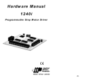
8/23/02
JK
User’s Manual
Hub444
Motion Control Network Hub
Applied Motion Products, Inc.
404 Westridge Drive Watsonville, CA 95076
Tel (831) 761-6555
(800) 525-1609
Fax (831) 761-6544
motors • drives • controls
-2-
-15-
Technical Specifications
Power
Contents
Runs on 5 VDC, 60 mA. Power is provided by Si™ indexer-drive
on Port 1. Also provides up to 40 mA for MMI via PC/MMI port.
Communication Ports 1 - 4: RS232, 9600 bps, 8 data bits, one stop bit, no parity.
MMI: same.
PC in router mode: same.
PC when running SiNet Hub Programmer software: 19200 bps.
Max cable length, any port: 50 feet.
Connectors
I/O: European style screw terminal blocks. Wire size: AWG 12 28.
Drives & PC/MMI: RJ11
Physical
Printed circuit board, 4.2 x 2.85 inches (107 x 72 mm). Weighs
2.7 ounces (75 grams). Two red LEDs. Operating temperature
range: 0 - 70° C. Optional DIN rail mounting kit (DMK-1).
Inputs
Optically isolated, differential 5-24V logic. 2200 ohms internal
resistance. 1.5 mA minimum “on” current.
Outputs
Optically isolated, darlington photo transistors. 30V, 100 mA
max.
Introduction ............................................................................................................... 4
Features ..................................................................................................................... 4
Getting Started .......................................................................................................... 5
Connecting the Hub .................................................................................................. 7
Programming - Router Mode..................................................................................... 8
Programming - Stored Program Mode ...................................................................... 9
About the MMI .......................................................................................................... 9
Cable Routing ........................................................................................................... 9
Programmable Inputs .............................................................................................. 10
Schematic Diagram of Programmable Input Circuit .......................................... 10
Sinking Circuits (NPN) ...................................................................................... 10
Sourcing circuits (PNP) ..................................................................................... 10
Connecting an Si™ Drive .................................................................................. 11
Connecting an NPN Type Proximity Sensor ....................................................... 11
Connecting a PNP Type Proximity Sensor ......................................................... 11
Programmable Outputs ............................................................................................ 12
Schematic Diagram of Output Circuit ................................................................ 12
Sinking Output ................................................................................................... 12
Sourcing Output ................................................................................................. 12
Driving a Relay ................................................................................................... 13
Mechanical Outline ................................................................................................. 13
Technical Specifications .......................................................................................... 14
Pin Assignments ..................................................................................................... 14
Pin Assignments
1
2
PC/MMI
ground (to PC ground)
TX (to PC RX)
RX (to PC TX)
+5VDC for MMI
(do not connect to PC)
PC/MMI Port
ground
TX (to drive RX)
RX (to drive TX)
+5VDC
Port 1
-14-
TX (to drive RX)
not used
ground
RX (to drive TX)
Ports 2 - 4
-3-
Introduction
Thank you for selecting an Applied Motion Products motion control device. We
hope our dedication to performance, quality and economy will make your motion
control project successful. If there’s anything we can do to improve our products or
help you use them better, please call or fax. We’d like to hear from you. Our phone
number is (800) 525-1609 or you can reach us by fax at (831) 761–6544.
relay
5-24 VDC
Power Supply
+
–
OUT+
Hub444
1N4935 suppression diode
OUT-
Features
• Can be programmed to control an entire multi-axis motion control system using
SiNet Hub Programmer™ software (included).
• Can also act as a router, allowing a host computer or PLC to control one to four
drives and the on-board I/O using Si™ Command Language (SCL)
• Four built-in programmable inputs, optically isolated, 5-24 VDC
• Four built-in programmable outputs, optically isolated, 24V 100mA max load
• Hub programs and host computers also have access to the I/O in each drive,
typically 8 inputs and 3 outputs per drive.
• Screw terminal connectors make I/O wiring easy.
• RJ11 “telephone-style” connectors for drives & PC for easy, reliable connections.
• Hub444 is powered by drive #1. No external power supply required.
• Can control and power optional MMI (operator terminal).
• Optional DIN rail mounting kit makes installation easy.
Compatible Indexers & Drives
All units have 8 programmable inputs and 3 programmable outputs or more
Si5580: runs on 120/240VAC, 80V bus, 5.5A/phase, 2000 - 50800 steps/rev
Si3540: runs on 120/240VAC, 40V bus, 3.5A/phase, 2000 - 50800 steps/rev
7080i: runs on 24 - 80 VDC, 7A/phase, 2000 - 50800 steps/rev
3540i: runs on 12 - 42 VDC, 3.5A/phase, 2000 - 50800 steps/rev
1240i: runs on 12 - 42 VDC, 1.2A/phase, 2000 - 50800 steps/rev
Si-100: indexer only, runs on 120/240VAC, provides industry standard step and
direction signals to a wide range of step motor and servo motor drives
BL7080i: open frame servo drive, 24 - 80 VDC, 7 amps continuous, 14 peak
BLSi7080: 120/240 VAC servo drive, 7 amps continuous, 14 peak
BLU100-S, BLU100-Si: 24 - 48 VDC servo drives, 100 watts
BLU200-S, BLU200-Si: 24 - 48 VDC servo drives, 200 watts
BLU1000-S, BLU1000-Si: 120/240 VAC servo drives, 1000 watts
-4-
Driving a Relay
Mechanical Outline
1
PC-MMI
2
2.85"
2.55"
3
4
HUB 444
IN
OUT
3.9"
4.2"
0.156" dia mounting holes
.670 max
.062
-13-
Programmable Outputs
Getting Started
The Hub444 provides four programmable outputs that can be used to drive LEDs,
relays and the inputs of other electronic devices like PLCs and counters. The “+”
(collector) and “-” (emitter) terminals of each transistor are available at the connector. This allows you to configure each output for current sourcing or sinking.
Diagrams of each type of connection are shown below.
Do not connect the outputs to more than 30VDC.
The current through each output terminal must not exceed 100 mA.
+5V
inside Hub444
330
OUT1+
OUT1–
The SiNet™ Hub444 can be used two different ways. You must choose based on
your application.
Stored Program Mode is easy. Just install our SiNet Hub Programmer™ software
on your PC, and point and click your way to a completed program. Once you’re
done preparing and testing your program, it stays inside the hub and runs without
the PC. Your program not only controls up to 4 motion control axes, it can also
interact with an operator using our Man Machine Interface (MMI). The MMI lets
the operator make decisions, choose operations from a menu, visually position your
load, and enter part counts, move distances and speeds.
processor
Optoisolator
NEC PS2502
or equiv.
The SiNet Hub Programmer™ software not only saves you time because it’s easy to
learn and easy to use, it also eliminates most of the things that can go wrong
during the set up and programming of a system.
Schematic Diagram of Output Circuit
We highly recommend that you try the SiNet Hub Programmer™ software before
considering Router Mode.
5-24 VDC
Power Supply
+
–
Load
OUT+
Hub444
OUT-
Sinking Output
5-24 VDC
Power Supply
+
–
OUT+
COMMON
OUT-
INPUT
Hub444
Sourcing Output
-12-
PLC
To use your SiNet™ Hub in Stored Program Mode, you will need:
✔ at least one Si™ step motor or servo motor drive
✔ a motor for each drive
✔ a small flat blade screwdriver for tightening the connectors - an Applied Motion
Products screwdriver suitable for this purpose is included with your drive.
✔ a 5-24 volt DC power supply may be required to use the isolated I/O
✔ a Pentium or better PC running Windows 95, 98, 2000, ME, XP or NT with an
unused 9 pin serial port. The SiNet Hub Programmer™ software does not run with
Windows 3.1.
✔ a PC serial interface cable (it comes with your Si™ indexer/drive)
✔ a modular telephone line cord for each indexer/drive (the hub comes with one 7
foot cable, and each drive includes a 7 foot cord. You can get longer cords anywhere telephone cords are sold, such as your local supermarket, discount store or
Radio Shack)
Router Mode is for systems where you will be using your own software to control
multiple indexer-drives. The Hub routes commands to individual drives based on
address characters that your software sends along with the commands. It also
-5-
Si™ drive
To use your SiNet™ Hub in Router Mode, you will need:
✔ at least one Si™ step motor or servo motor drive
✔ a motor for each drive
✔ a small flat blade screwdriver for tightening the connectors - an Applied Motion
Products screwdriver suitable for this purpose is included with your drive.
✔ a 5-24 volt DC power supply may be required to use the isolated I/O
✔ a PC running Windows 95, 98, 2000, ME, NT or XP with an unused 9 pin serial
port.
✔ a PC serial interface cable (it comes with your Si™ indexer/drive)
✔ a modular telephone line cord for each indexer/drive (the hub comes with one 7
foot cable, and each drive includes a 7 foot cord. You can get longer cords anywhere telephone cords are sold, such as your local supermarket, discount store or
Radio Shack)
✔ your own custom software to command and query the indexer/drives using Si™
Command Language (SCL). This means you need a highly skilled computer
programmer working with a language system like C, Visual Basic or Labview.
+
IN+
OUT+
IN-
Hub
routes messages from the drives back to the host PC or PLC. In Router Mode, the
indexer-drives are commanded and queried using SiNet Command Language (SCL).
Router Mode is the most versatile way to use the hub, but also the most difficult
because you’ll need a highly skilled programmer to write your host software.
OUT–
-
5-24
VDC
Power
Supply
Connecting an Si™ Drive
When drive output closes, Hub input goes low (closed).
5-24 +
VDC
Power
Supply -
IN+
+
output
NPN
Proximity
Sensor
–
INHub444
Connecting an NPN Type Proximity Sensor
When prox sensor activates, input goes low (closed).
The sketch below identifies some of the features of the SiNet™ Hub. Please
examine it now.
Connect to PC for programming
Drive #1
(required)
Drives #2,3,4
(optional)
1
2
PC-MMI
3
POWER
4
COMM
HUB 444
IN
OUT
5-24 +
VDC
Power
Supply -
+
output
PNP
Proximity
Sensor
–
Hub444
IN-
Connecting a PNP Type Proximity Sensor
When prox sensor activates, input goes low (closed).
4 programmable inputs
4 programmable outputs
comm LED
flashes when communicating with PC or MMI
-6-
IN+
-11-
Programmable Inputs
Connecting the Hub
The Hub444 provides four digital inputs for external equipment such as sensors,
switches and other electronics. These inputs are optically isolated, and allow a
wide range of input voltages to be used. Each input gives you the option of using
sinking or sourcing signals.
All connections between the PC, the hub and the Si™ drives are made using four
wire cables with RJ11 connectors. These are the same cords used to connect a
telephone or modem to the wall jack. You’ll also need a small black “modular
adaptor” that allows the RJ11 cable to connect to the serial port on your PC. A
modular adaptor is included with each Si™ drive.
A schematic diagram of the input circuit is shown below.
IN+
2200
IN-
Schematic Diagram of Programmable Input Circuit
Note: never connect the SiNet hub to a telephone outlet or to the
modem port of your PC.
Note: if you decide to make your own cables, make sure that the ends
are terminated just like a telephone cord, as shown below. If you mess
this up, you could seriously damage the hub, your drives or your PC. If
in doubt, don’t make your own cables.
yellow
green
red
black
yellow
green
red
black
Sinking Circuits (NPN)
If your output devices prefer to sink current, then connect the “+” terminals to your
positive power supply, and the “-” terminals to your signals. If you are using a TTL
circuit to drive the hub inputs, connect the “+” terminals to your 5 volt bus. No
ground connection is needed. If you are using a PLC or proximity sensor, you’ll
need a power supply.
LIMITS
CW+
CWIN 1
CCW+
IN 2
CCWIN 3
GND
IN 4
GND
JOG CW
+5V
JOG CCW
+5V
GND
GND
POWER
OVER TEMP
OVER CURRENT
OUT 1+
OUT 1OUT 2+
OUT 2OUT 3+
OUT 3FAULT+
FAULT-
STOP
RS232
You must supply 5-24 volts DC to supply current to the LEDs on the input side of
the optoisolators. Most CMOS and open collector TTL devices are directly compatible with this drive, as are typical PLC and proximity sensor outputs.
You can use longer cables, up to 50 feet. Telephone line cords are easily available
at your local supermarket, discount or electronics store.
Si5580
AC POWER
N
L
1
IN1
IN2
IN3
IN4
CWJOG/IN5
CCWJOG/IN6
LIMIT COM
CW LIMIT
CCW LIMIT
Si-100
LIMITS
CW +
CW CCW +
CCW OUT 1 +
OUT 1 OUT 2 +
OUT 2 OUT 3 +
OUT 3 -
PC / MMI
POWER
BB+
AA+
Motion Controller
STOP
PC/MMI
IN / JOG COM
IN / JOG COM
INPUT 1
INPUT 2
INPUT 3
INPUT 4
IN 5 / JOG CW
IN 6 / JOG CCW
MOTOR
Si3540 Programmable Step Motor Driver
Note: We refer to an input as being ON or CLOSED when current is
flowing through the input. A signal is OFF or OPEN when no current is
flowing. An input is OPEN when the “+” and “-” input terminals are at
the same voltage, or when the input is left unconnected.
B–
B+
A–
A+
GND
IN/JOG COM
2
PC-MMI
3
POWER
4
COMM
POWER
AC POWER
G
L2/N
L1
G
AC
POWER
Sourcing circuits (PNP)
If your output devices can only source current (some PLC outputs are this way),
connect the “-” terminals to the ground of the DC power supply that powers your
output circuits. Then connect your signals to the “+” terminals.
MOTOR
Step Motor Driver
+24 VDC
24V GND
+5 VDC
GND
STEP+
STEP–
DIR+
DIR–
OUT1+
OUT1–
OUT2+
OUT2–
OUT3+
OUT3–
N
L
HUB 444
-10-
IN
-7-
OUT
Programming - Router Mode
When operated in router mode, the Hub444 is a motion control network router. It
transfers commands from your PC’s serial port to individual Si™ drives (up to 4) ,
and processes responses from the drives.
In router mode, the drives are commanded using Si™ Command Language (SCL).
The Si™ Command Language is explained in the latest copy of the SCL Manual, which is
shipped with the drives. You can use one of the cables that comes with the drives to
connect the Hub to your PC. Ordinary telephone cables are used to connect the hub to the
drives. The hub operates at 9600 baud, 8 data bits, one stop bit, no parity. There is no
hardware handshaking.
The Hub444 requires no power supply. It gets the power it needs from drive #1, so make
sure you have a drive connected to port #1
#1. You can apply power to all the drives at the
same time. However, you may want to power up the drives “sequentially” to balance the
load on your power circuit. If you do not power up all the drives together
together,, make sure
you apply power to drive #1 first. The remaining drives must receive power within
1/2 second.
The Hub has two status LEDs marked COMM and POWER. If you have a drive connected
to port #1 and that drive has power, then the POWER LED on the Hub should light up.
The COMM LED will flash each time a command is sent from the PC to the Hub. You can
use our SCL Setup Utility to test the Hub, and to get familiar with SCL commands. The
SCL Setup Utility is shipped with the hub. To use the hub in router mode, you’ll
need to set the “power up mode” to “router only.” The SCL Setup Utility
allows you to control the power up mode. Simply connect the hub to your PC, open the
SCL Setup Utility, then apply power to the hub. A “Hub Power Up Mode...” button will
appear. Click on it.
the host “4R” (assuming the drive is “ready.” If it’s moving, you’ll see the response “4M”.)
This is helpful if you send a global status request, since all drives will respond at the same
time.
Programming - Stored Program Mode
In this mode, a multi-axis motion control program is stored inside the hub, and the hub
then operates without the PC. The PC is used to develop and test your program with the
aid of our SiNet Hub Programmer™ software.
Please refer to the SiNet Hub Programmer™ Software Manual when installing the software
and developing programs.
About the MMI
In the event that you want to create a system where a machine operator can interact with a
display and keypad you may be interested in one of our “Man Machine Interfaces” (MMI).
The Hub Programmer software supports the MMI-01 and the new, backlit MMI-02.
The MMI connects to the same port as the PC that you use to develop and test your
program. At this point you may be thinking “Does that mean I have to swap cables
between the PC and MMI while I’m testing my program?” Fear not, we have included an
“MMI Emulator” in the Hub Programmer software, Anytime you are in running your
program from the PC and an MMI related instruction executes, a “virtual MMI” will appear
on your computer screen. This not only relieves you of having to swap cables, it also
allows you to try out the MMI features before you actually purchase one.
Cable Routing
The Hub444 makes it easy to create multi-axis distributed systems which require both
senstive network communication cables and high power cables for each remote axis.
These two classes of cables should not be run together in a common conduit or raceway.
The addressing scheme is simple. If you want to send a Feed to Length command to the
drive connected to port #1, send the hub the ascii string “1FL” followed by a carriage
return (ascii 13). If you omit the address character, the command is “global” and will be
sent to all drives. That is useful is you want to send the same parameter (accel rate, for
example) to all the drives.
If you ask a drive for status information, the hub will append an address character to the
drive’s response. For example, sending “4RS” to the hub will result in the hub sending
-8-
-9-