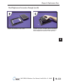
1
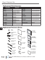
REPLACEMENT PARTS
CHAPTER
9
In This Chapter...
Replacement Parts Overview . . . . . . . . . . . . . . . . . . . . . . . . . . . . . . . . . . . . . . . . . .9–2
Replacement Parts at a Glance . . . . . . . . . . . . . . . . . . . . . . . . . . . . . . . . . . . . . . . . .9–2
Battery Replacement & Installation Instructions . . . . . . . . . . . . . . . . . . . . . . . . . . .9–3
6” Panel Mounting Clip Replacements & Installation . . . . . . . . . . . . . . . . . . . . . . .9–5
8-15” Panel Mounting Clip Replacements & Installation . . . . . . . . . . . . . . . . . . . .9–6
DC Panel Power Connector Replacement . . . . . . . . . . . . . . . . . . . . . . . . . . . . . . . .9–7
AC Power Adapter Connector Replacement . . . . . . . . . . . . . . . . . . . . . . . . . . . . . .9–7
8-15” Panel Backlight Bulb Replacements & Installation . . . . . . . . . . . . . . . . . . . .9–8
6-15” Panel Gasket Replacement & Installation . . . . . . . . . . . . . . . . . . . . . . . . . .9–11
8-15” Panel Bezel Replacement & Installation . . . . . . . . . . . . . . . . . . . . . . . . . . . .9–12
6” Adapter Plate Gasket Replacement & Installation . . . . . . . . . . . . . . . . . . . . . .9–14
Chapter 9: Replacement Parts
Replacement Parts Overview
Part Number
Part Number
Description
1
D2-BAT-1
EA-12-GSK
2 EA-BRK-1
EA-10-GSK
EA-8-GSK
3 EA-BRK-2
EA-DC-CON
EA-6-GSK
4 EA-AC-CON
EA-15-BEZEL
EA-12-BEZEL
5 EA-15-BULB
EA-12-BULB
EA-10-BEZEL
EA-8-BEZEL
6 EA-10-BULB
EA-6-ADPTR-GSK
7 EA-8-BULB
EA-15-GSK
8
Replacement Parts at a Glance:
9
10
11
12
13
14
A
B
C
D
Description
Battery Replacement
12" Panel Gasket Replacement
6” Panel Mounting Clip
Replacements (2 per pk.)
8-15” Panel Mounting Clip
Replacements (8 per pk.)
DC Panel Power Connector
Replacement
AC Power Adapter Connector
Replacement
15" Panel Backlight Bulb
Replacement
12" Panel Backlight Bulb
Replacement
10" Panel Backlight Bulb
Replacement
8" Panel Backlight Bulb
Replacement
10" Panel Gasket Replacement
8" Panel Gasket Replacement
6" Panel Gasket Replacement
15" Panel Bezel Replacement
12" Panel Bezel Replacement
10" Panel Bezel Replacement
8" Panel Bezel Replacement
6” Adapter Plate Gasket
Replacement
15" Panel Gasket Replacement
Battery:
D2-BAT-1
6 inch mounting clips:
EA-BRK-1
(pk of 2)
15 inch gasket:
EA-15-GSK
8 - 15 inch mounting clips:
EA-BRK-2
(pk of 8)
DC power connector:
EA-DC-CON
12 inch gasket:
EA-12-GSK
AC power connector:
EA-AC-CON
15 inch backlight:
EA-15-BULB
12 inch backlight:
EA-12-BULB
10 inch gasket:
EA-10-GSK
8 inch gasket:
EA-8-GSK
15 inch Bezel:
EA-15-BEZEL
(gasket not included)
12 inch Bezel:
EA-12-BEZEL
(gasket not included)
10 inch Bezel:
EA-10-BEZEL
(gasket not included)
8 inch Bezel:
EA-8-BEZEL
(gasket not included)
Note: 6 inch bezel is
not user replaceable.
10 inch backlight:
EA-10-BULB
8 inch backlight:
EA-8-BULB
9–2
®
6 inch gasket:
EA-6-GSK
6 inch Adapter Plate
replacement gasket
EA-6-ADPTR-GSK
EA-USER-M Hardware User Manual, 2nd Ed. Rev. D, 10/09
Chapter 9: Replacement Parts
Battery Replacement – D2-BAT-1
CAUTION - The battery used in this device may present a risk of fire or chemical burn if mistreated. Do
not recharge, disassemble, heat above 100 °C (212 °F) or incinerate. Replace battery with
AutomationDirect part number D2-BAT-1 or CR2354 only. Use of another battery may present a risk of
fire or explosion. Dispose of used battery properly. Keep away from children.
Perchlorate Material, special disposal handling may apply
The C-more touch panels are supplied with a SRAM retentive memory backup battery that also
is used to backup the internal CPU date/time registers. The battery should be replaced every 5
years or during any routine maintenance to the touch panel. As a note, the battery used in the
C-more touch panels is the same battery that is used for backup in AutomationDirect’s DL06,
D2-250(-1), D2-260 and D3-350 PLCs.
Battery Replacement Instructions:
NOTE: The lithium battery in your panel is used to maintain the system SRAM retentive memory and the CPU
date/time registers when the unit is without external power. Before replacing the battery, back-up the data in
your SRAM retentive memory as a precaution. Input power needs to be maintained to the panel during battery
replacement. Typical battery life is five years, which includes panel runtime and normal shutdown periods.
However, consider installing a fresh battery if your battery has not been replaced recently and the unit will be
without power for a period of more than ten days.
Preparation: If the touch panel is not mounted in or has been removed from a control cabinet, then it is recommended the panel be
placed face down on a lint-free soft surface to prevent scratching the front of the panel. The battery door is located on the rear just below
and to the left of the DC Power Connector.
DC Power
Connector
1
2
Battery door
latch tab
Open the battery holder door by pressing down on the upper
latch tab while lifting upward and rotating the door in a
downward motion. The battery door will pivot toward its
bottom hinge point.
The coin cell style battery is located in the battery holder. To
remove the battery, use the slot in the top of the holder to
pry the battery away from the holder and while grasping the
battery, lift it upward.
Continued on next page.
®
EA-USER-M Hardware User Manual, 2nd Ed. Rev. D, 10/09
1
2
3
4
5
6
7
8
9
10
11
12
13
14
A
B
C
D
9–3
Chapter 9: Replacement Parts
Battery Replacement Instructions (cont’d):
1
2
3
4
5
6
7
8
9
10
11
12
13
14
A
B
C
D
3
4
Battery
retaining tab
Above shows the empty battery holder and also points out
the location of the battery retaining tab for reference in the
next step.
To install the battery, hold the battery so that the larger
diameter (+ symbol) is outward. Set the battery to the inside
of the retaining tab and then press the upper top of the
battery into the holder.
5
Press the battery holder door downward until the upper
latch tab locks into place. Make a note of the date the battery
was installed.
9–4
CAUTION - The battery used in this device may present a risk of fire or chemical burn if mistreated. Do
not recharge, disassemble, heat above 100 °C (212 °F) or incinerate. Replace battery with
AutomationDirect part number D2-BAT-1 or CR2354 only. Use of another battery may present a risk of
fire or explosion. Dispose of used battery properly. Keep away from children.
Additional precautions:
• Do not short circuit the battery and be sure to make the correct polarity connections.
• Avoid extremely high or low temperatures and high humidity when storing.
• Do not dismantle the battery.
Perchlorate Material, special disposal handling may apply
®
EA-USER-M Hardware User Manual, 2nd Ed. Rev. D, 10/09
Chapter 9: Replacement Parts
6” Panel Mounting Clip Replacements – EA-BRK-1
Spare panel mounting clips for 6 inch C-more touch panels.
Package of 2 clips with 4 screws.
3
Installation Instructions
1
Tighten the mounting screws in an alternating fashion while
observing the front of the touch panel. The goal is to make
sure the front bezel is pulled up against the enclosure sheet
metal uniformly, and the touch panel gasket is fully
compressed all the way around its perimeter. Tighten the
screws to a torque rating shown in the table below. Avoid
over-tightening the screws to the point that they start to
deform or bend the mounting clip.
Position the touch panel through the cutout in the control
cabinet door and hold in place. The mounting clips can be
positioned into one of two different set of slots for different
cabinet thicknesses. See table below.
4
2
The above photo shows both mounting clips in place and
the touch panel secured.
The above photo shows one mounting clip in place. The
example is using the lower mounting clip slots that
accommodates an enclosure thickness of 0.039 – 0.24
inches [1 – 6 mm]. The upper slots can be used for an
enclosure thickness of 0.20 – 0.63 inches [5 – 16 mm].
®
Touch
Panel Size
Enclosure
Thickness
Range
Mounting Clip
Screw Torque
6”
lower mounting
clip position
0.039 - 0.24 inch
[1 – 6 mm]
35 ~ 50 oz-in
[0.25 ~ 0.35 Nm]
6”
upper mounting
clip position
0.20 - 0.63 inch
[5 – 16 mm]
35 ~ 50 oz-in
[0.25 ~ 0.35 Nm]
EA-USER-M Hardware User Manual, 2nd Ed. Rev. D, 10/09
1
2
3
4
5
6
7
8
9
10
11
12
13
14
A
B
C
D
9–5
Chapter 9: Replacement Parts
1
2
3
4
5
6
7
8
9
10
11
12
13
14
A
B
C
D
8–15” Panel Mounting Clip Replacements– EA-BRK-2
Spare panel mounting clips for the 8 inch through 15 inch
C-more touch panels. Package of 8 clips with 8 screws.
3
Installation Instructions
1
Tighten the mounting screw for each mounting clip in an
alternating fashion at all clips while observing the front of
the touch panel. The goal is to make sure the front bezel is
pulled up against the enclosure sheet metal uniformly, and
the touch panel gasket is fully compressed all the way
around its perimeter. Tighten the screws to a torque rating
shown in the table below. Avoid over-tightening the screws
to the point that they start to deform or bend the mounting
clip.
Position the touch panel through the cutout in the control
cabinet door and hold in place. The mounting clips are
positioned into the slots around the outside edge of the
touch panel rear.
4
2
The above photo shows all mounting clips in place and the
touch panel secured. The 8”, 10” and 12” touch panels
require 6 mounting clips and the 15” touch panel requires 8
mounting clips.
The mounting clips are positioned into the larger portion of
the slot at two locations, and then slid toward the smaller
portion of the slots to lock them in place. Some slots are
arranged to slide to the left and others to the right.
9–6
®
Touch
Panel Size
Enclosure
Thickness
Range
Mounting Clip
Screw Torque
6”
upper mounting
clip position
0.20 - 0.63 inch
[5 – 16 mm]
35 ~ 50 oz-in
[0.25 ~ 0.35 Nm]
EA-USER-M Hardware User Manual, 2nd Ed. Rev. D, 10/09
Chapter 9: Replacement Parts
DC Panel Power Connector Replacement – EA-DC-CON
C-more touch panel 5-position DC power connector terminal block replacement. One (1) DC
Power Connector is supplied with each touch panel.
Recommended DC Supply Fuse
Panel Size Rating
6“ – 10”
2.5 A
12“ & 15”
4.0 A
ADC p/n
MDL2-5
MDL4
+
24 VDC, -15%, +20%
(20.4 - 28.8 VDC)
Tightening Torque
Power supply
cable torque
71 - 85 oz-in (0.5 - 0.6 Nm)
–
GND
PWR
CPU
Equipment
Ground
NOTE: Use 60 / 75 °C copper
conductors only.
BATT
AC Power Adapter Connector Replacement– EA-AC-CON
C-more AC power adapter 3-position AC power connector terminal block replacement.
One (1) AC Power Connector is supplied with each AC/DC Power Adapter, EA-AC.
AC Power Adapter
Not recommended for use with the EA7-T15C
when operating temperatures are expected
to be above 40 deg C.
Tightening Torque
Power supply
71 - 85 oz-in (0.5 - 0.6 Nm)
cable torque
Mounting flange 57 - 71 oz-in (0.4 - 0.5 Nm)
screw torque
NOTE: Use 60 / 75 °C copper
conductors only.
®
Recommended AC Supply Fuse
3.0 A time delay, ADC p/n MDL3
100 - 240 VAC
50/60 Hz
EA-USER-M Hardware User Manual, 2nd Ed. Rev. D, 10/09
1
2
3
4
5
6
7
8
9
10
11
12
13
14
A
B
C
D
9–7
Chapter 9: Replacement Parts
8-15” Panel Backlight Bulb Replacements – EA-xx-BULB
Backlight assembly, customer replaceable, for C-more 8”, 10”, 12”
1
and 15” touch panels. The 8”, 10” and 15” touch panels use two
bulbs per panel and the 12” touch panels use one bulb per panel.
2
The bulbs are packaged two per box for the 8”, 10” and 15” touch
panels and one per box for the 12” touch panels.
3
(The part number is completed by substituting the panel size, 08,
10, 12 or 15, for the xx shown above.)
4
5
Backlight Bulb Installation Instructions Example:
6
(See the Data Sheet insert for the specific backlight bulb that is being replaced for more detailed
information.)
7
W
: This procedure should only be performed by qualified personnel who are experienced in
working with electronic equipment. Take the necessary steps to prevent damage from static electricity
8
discharge. Disconnect input power to the touch panel before proceeding. Be careful not to pinch the
ribbon cable between the housing and bezel when re-assembling the panel.
9
10
11
2
1
12
13
14
A
B
C
D
ARNING
Preparation: Disconnect input power and all other connections, then remove the touch panel from the control cabinet. In a clean
environment, place the panel face down on a lint-free soft surface to prevent scratching the front of the panel.
Ribbon cable
recess
With power disconnected, use a #2 Phillips screwdriver to
remove the four outer screws holding the touch panel’s main
electronics housing to the front bezel.
Lift the touch panel’s main electronics housing from the
front bezel. Set the front bezel and four screws to the side.
Observe the ribbon cable recess on the front bezel (see
detail) for use in re-assembling the panel.
Continued on next page.
9–8
®
EA-USER-M Hardware User Manual, 2nd Ed. Rev. D, 10/09
Chapter 9: Replacement Parts
Backlight Bulb Installation Instructions Example (cont’d):
3
Upper & lower backlight
bulb connectors
Place the touch panel’s main electronics housing facing up
on a lint-free soft surface. Position the housing so that the
backlight bulb connectors are in plain view.
5
4
Carefully lift the bulb’s wires out of the wire guides so they
are free from obstructions. Do this for both the upper and
lower backlight bulbs.
6
Unplug the backlight bulb’s power cable connector from the
circuit board connector. Again, do this for both the upper
and lower backlight bulbs.
7
Push up on the bulb retaining clip (see detail) while grasping
the plastic end of the bulb assembly and gently slide the bulb
from its guide. Do this for both bulbs. The bulb is glass and
fragile, so handle with care.
8
This photo shows the backlight bulb completely removed
from its guide in the panel’s main electronics housing. (Only
one bulb shown.)
Bulb
retaining clip
Note: The two replacement bulbs are
labeled “Upper” and “Lower”. This is because
the bulbs have different cable lengths for
reaching the circuit board connector.
Remove the replacement bulb from its shipping tube and the
protective bubble wrap. Note: The replacement bulbs come
in pairs and should be replaced in pairs for longevity and
maintenance convenience.
Continued on next page.
®
EA-USER-M Hardware User Manual, 2nd Ed. Rev. D, 10/09
1
2
3
4
5
6
7
8
9
10
11
12
13
14
A
B
C
D
9–9
Chapter 9: Replacement Parts
Backlight Bulb Installation Instructions Example (cont’d):
1
2
3
4
5
6
7
8
9
10
11
12
13
14
A
B
C
D
9
10
Position the replacement bulb so that the opening in its
three-sided gold colored reflector faces toward the LCD
touch screen. Using gentle pressure, slide the bulb into the
guide until the retaining clip locks.
11
12
Gently position each backlight bulb’s wires back into their
respective wire guides to help clear any obstructions when
inserting the panel’s main electronics housing back into the
front bezel. Position any excess wire length in between the
printed circuit board and the LCD to prevent it from
becoming pinched between the housing and bezel.
9–10
Plug each backlight bulb’s power cable connector back into
its respective circuit board connector.
®
Position the touch panel’s main electronics housing into the
front bezel so that the flat ribbon cable on the housing aligns
with the recess in the front bezel. Insert the four screws and
tighten to a maximum of 70 oz-in [0.5 Nm].
EA-USER-M Hardware User Manual, 2nd Ed. Rev. D, 10/09
Chapter 9: Replacement Parts
6-15” Panel Gasket Replacements – EA-xx-GSK
Replacement NEMA 4/4X touch panel gaskets for C-more 6”,
8”, 10”, 12” and 15” touch panels.
(The part number is completed by substituting the panel size,
06, 08, 10, 12 or 15, for the xx shown above.)
Gasket Replacement Installation Instructions:
Preparation: Disconnect input power and all other connections, then remove the touch panel from the control cabinet. In a clean
environment, place the panel face down on a lint-free soft surface to prevent scratching the front of the panel.
1
2
Start at one corner and pull the old gasket out of the channel
that holds the gasket in place. Pull the gasket up as you work
around the entire perimeter of the touch panel. Discard the
old gasket.
®
Lay the new gasket over the channel so that the long and
short sides of the gasket match up to the long and short
sides of the touch panel. Start at one corner and match the
gasket’s corner to the channel’s corner. Press the gasket into
the channel and work all away around the perimeter of the
touch panel. Re-install the touch panel.
EA-USER-M Hardware User Manual, 2nd Ed. Rev. D, 10/09
1
2
3
4
5
6
7
8
9
10
11
12
13
14
A
B
C
D
9–11
Chapter 9: Replacement Parts
8-15” Panel Bezel Replacement – EA-xx-BEZEL
The NEMA 4/4X bezels used on the C-more 8”, 10”, 12” and
1
15” touch panels can be easily replaced. The replacement bezel
includes the clear membrane element that protects the touch
2
sensitive area. A gasket is not included. The bezel and
membrane element do not require replacement under normal
3
use. In the event that the clear membrane is scratched from the
use of sharp objects or abrasive materials, follow the procedure
outlined below to replace the front bezel.
4
(The part number is completed by substituting the panel size,
08, 10, 12 or 15, for the xx shown above.)
5
Note: The bezel on the 6” C-more touch panels is not user replaceable and can only be replaced by
AutomationDirect. Contact the AutomationDirect returns department @ 1-800-633-0405 to make
6
arrangements for returning the unit for repair.
7
8 Bezel Replacement Instructions Example:
W
: This procedure should only be performed by qualified personnel who are experienced in working
9
with electronic equipment. Take the necessary steps to prevent damage from static electricity discharge.
Disconnect input power to the touch panel before proceeding. Be careful not to pinch the ribbon cable
between the housing and bezel when re-assembling the panel.
10
11
12
2
1
13
14
A
B
C
D
ARNING
Preparation: Disconnect input power and all other connections, then remove the touch panel from the control cabinet. In a clean
environment, place the panel face down on a lint-free soft surface to prevent scratching the front of the panel.
Ribbon cable
recess
With power disconnected, use a #2 Phillips screwdriver to
remove the four outer screws holding the touch panel’s main
electronics housing to the front bezel.
Lift the touch panel’s main electronics housing from the
front bezel. Set the four screws to the side and discard the
original bezel. Observe the ribbon cable recess on the front
bezel (see detail) for use in re-assembling the panel.
Continued on next page.
9–12
®
EA-USER-M Hardware User Manual, 2nd Ed. Rev. D, 10/09
Chapter 9: Replacement Parts
Bezel Replacement Instructions Example (cont’d):
4
3
Place the new bezel facing down on the lint-free soft surface
along with main electronics and four screws.
®
Position the touch panel’s main electronics housing into the
new bezel so that the flat ribbon cable on the housing
matches up with the recess in the front bezel. Insert the four
screws and tighten to a maximum of 70 oz-in [0.5 Nm].
EA-USER-M Hardware User Manual, 2nd Ed. Rev. D, 10/09
1
2
3
4
5
6
7
8
9
10
11
12
13
14
A
B
C
D
9–13
Chapter 9: Replacement Parts
6” Adapter Plate Gasket Replacement – EA-6-ADPTR-GSK
1
6-inch replacement NEMA 4/4X gasket for the C-more touch
panel adapter plate.
2
3
4
5
6 6” Adapter Plate Gasket Replacement Instructions:
7
8
9
2
1
10
11
12
13
14
A
B
C
D
Preparation: Disconnect input power and all other connections, remove the touch panel from the 6” adapter plate, and then remove the
adapter plate from the control cabinet by removing the six (6) screws that secure the adapter to the control cabinet. In a clean
environment, place the adapter plate face down on a lint-free soft surface to prevent scratching the adapter plate.
Start at one corner and pull the old gasket out of the channel
that holds the gasket in place. Pull the gasket up as you work
around the entire perimeter of the adapter plate. Discard the
old gasket.
9–14
®
Lay the new gasket over the channel so that the long and
short sides of the gasket match up to the long and short
sides of the adapter plate. Start at one corner and match the
gasket’s corner to the channel’s corner. Press the gasket into
the channel and work all away around the perimeter of the
adapter plate. Re-install the adapter plate and then the touch
panel.
EA-USER-M Hardware User Manual, 2nd Ed. Rev. D, 10/09