1
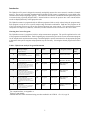
hydroscout
®
For the Determination of Water Content
User’s Manual
Version E32
Copyright Notice
HydroScout User's Manual and other documentation copyright © 2001-2003 Dexsil Corporation. All
rights reserved.
Disclaimer
Dexsil Corporation makes no representations or warranties with respect to the contents
hereof and specifically disclaims any implied warranties of merchantability or fitness for
any particular purpose. Further, Dexsil Corporation reserves the right to revise this
publication and to make changes from time to time in the contents hereof without
obligation of Dexsil Corporation to notify any person of such revision or changes.
Trademarks
HydroScout and Dexsil are registered trademarks of Dexsil Corporation
DEXSIL Corporation
One Hamden Park Drive
Hamden, Ct. 06517
Tel: (203) 288-3509; Fax: (203) 248-6523; http://www.dexsil.com
HYDROSCOUTManualE32.RV0.wpd
Version E32 Rev0 February 2006
WARNING!
READ ALL CAUTIONS BEFORE USING THIS TEST!
ONCE THE TEST IS INITIATED, CONTENTS OF THE TUBES ARE UNDER PRESSURE.
SAFETY GLASSES MUST BE WORN AT ALL TIMES WHILE PERFORMING TESTS. DO NOT
REMOVE THE WHITE CAP AFTER THE TEST HAS BEEN PERFORMED.
DO NOT USE THIS TEST ON CONCENTRATED ACIDS. THE EXCESSIVE HEAT
GENERATED MAY LEAD TO TUBE FAILURE.
DO NOT USE 5 ML SAMPLES OF PHOSPHATE ESTER-BASED HYDRAULIC FLUIDS,
GASOLINE OR SOLVENTS SUCH AS ACETONE. THESE SAMPLES WEAKEN THE
TUBES WHICH MAY RESULT IN TUBE FAILURE.
THE TEST CONTAINS FLAMMABLE SOLVENTS AND PRODUCES HYDROGEN GAS; KEEP
AWAY FROM OPEN FLAME.
MAKE SURE THE BLACK SEPTUM IS FULLY INSERTED INTO THE NECK OF THE TEST
TUBE AND THE WHITE CAP IS SCREWED ON TIGHTLY.
SHAKE THE TUBE WHILE POINTING IT AWAY FROM YOURSELF AND BYSTANDERS.
WHEN CRUSHING THE GLASS AMPULE, PRESS FIRMLY IN THE CENTER OF THE GLASS
AMPULE. NEVER ATTEMPT TO RECRUSH BROKEN GLASS AS IT CAN PENETRATE THE
PLASTIC TUBE AND CUT FINGERS.
THE GRAY AMPULE IN THE TUBES CONTAINS CALCIUM HYDRIDE WHICH IS A
FLAMMABLE SOLID AND IS WATER REACTIVE.
IN CASE OF ACCIDENTAL BREAKAGE OR SPILLAGE ONTO SKIN OR CLOTHING, WASH
IMMEDIATELY WITH LARGE AMOUNTS OF WATER. DO NOT TAKE INTERNALLY, ALL
OF THE CONTENTS ARE POISONOUS.
KEEP OUT OF THE REACH OF CHILDREN
READ MATERIAL SAFETY DATA SHEETS BEFORE PERFORMING TEST.
MANUFACTURER’S WARRANTY
This kit is warranted to be free of defects in material and workmanship until the expiration date stamped on
the box. Manufacturer’s sole and exclusive liability under this warranty shall be limited to replacement of
any kit that is proved to be defective. Manufacturer shall not be liable for any incidental or consequential
damages.
Reliable test results are highly dependent upon the care with which the directions are followed and,
consequently, cannot be guaranteed.
Table of Contents
Introduction
...........................................................1
Choosing the Correct Program . . . . . . . . . . . . . . . . . . . . . . . . . . . . . . . . . . . . . . . . . . . . . . . . 1
Table 1: HydroScout Analysis Program Information . . . . . . . . . . . . . . . . . . . . . . . . . . 1
Programs A & B - For Mid to High Range Water in Oil . . . . . . . . . . . . . . . . . . . . . . . 2
Programs C, D & E - For Low Level Water in Oil . . . . . . . . . . . . . . . . . . . . . . . . . . . 2
Program F - For Water in Soils and Solids . . . . . . . . . . . . . . . . . . . . . . . . . . . . . . . . . 2
Meter Operation . . . . . . . . . . . . . . . . . . . . . . . . . . . . . . . . . . . . . . . . . . . . . . . . . . . . . . . . . . 3
Turning the Meter On . . . . . . . . . . . . . . . . . . . . . . . . . . . . . . . . . . . . . . . . . . . . . . . . . 3
Making a Measurement . . . . . . . . . . . . . . . . . . . . . . . . . . . . . . . . . . . . . . . . . . . . . . . 3
Selecting a Program . . . . . . . . . . . . . . . . . . . . . . . . . . . . . . . . . . . . . . . . . . . . . . . . . . 3
Turning the Meter Off . . . . . . . . . . . . . . . . . . . . . . . . . . . . . . . . . . . . . . . . . . . . . . . . . 3
Error Codes
...........................................................3
Table 2: Error Codes . . . . . . . . . . . . . . . . . . . . . . . . . . . . . . . . . . . . . . . . . . . . . . . . . 4
Interferences
...........................................................4
Step by Step Instructions for Meter Operation . . . . . . . . . . . . . . . . . . . . . . . . . . . . . . . . . . . . 5
Analysis Instructions for Each Sample Type and Analysis Program . . . . . . . . . . . . . . . . . . . . . 5
Program A - Procedure for Testing Water Content up to 20% . . . . . . . . . . . . . . . . . . 5
Program B - Procedure for Testing Water Content up to 100% . . . . . . . . . . . . . . . . . 6
Program C, D & E - Procedure for Low Levels of Water (5 mL Sample Size) . . . . . . 7
Program F - Procedure for the Analysis of Water in Soils and Solids . . . . . . . . . . . . . . 8
Appendix A: Comparison Data . . . . . . . . . . . . . . . . . . . . . . . . . . . . . . . . . . . . . . . . . . . . . . . . 9
Water in Used Oil (Programs A & B) . . . . . . . . . . . . . . . . . . . . . . . . . . . . . . . . . . . . . 9
Used Oil CRMs (Programs A & B) . . . . . . . . . . . . . . . . . . . . . . . . . . . . . . . . . . . . . . 9
Low Levels in Turbine and Gear Oil (Program C) . . . . . . . . . . . . . . . . . . . . . . . . . . . . 10
Low Level Water in Other Oils (Program D) . . . . . . . . . . . . . . . . . . . . . . . . . . . . . . . 11
Low Level Water in Other Oils (Program E) . . . . . . . . . . . . . . . . . . . . . . . . . . . . . . . . 12
Water in Soil (Program F) . . . . . . . . . . . . . . . . . . . . . . . . . . . . . . . . . . . . . . . . . . . . . 13
Appendix B: Meter Specifications . . . . . . . . . . . . . . . . . . . . . . . . . . . . . . . . . . . . . . . . . . . . . . 14
Introduction
The HydroScout™ system is designed to accurately and quickly measure the water content in a number of sample
matrices. The test uses a specially formulated calcium hydride (CaH2) reagent to quantitatively convert all the water
contained in the sample to hydrogen gas (H2). The reaction is carried out in a sealed tube and the generated pressure
is measured using a specially designed meter. Internal software converts the pressure into water content and the
results are displayed directly in the appropriate units.
The HydroScout meter is programed with six different programs which are easily selected using the program menu.
Each program is setup to cover a specific analysis range and matrix combination. Built into each program are all
of the conversions necessary to convert the measured pressure into water content. The measurement programs
compensate for sample size, dilutions, extractions, reaction efficiencies and conversion to the correct units.
Choosing the Correct Program
The HydroScout meter is programed with six unique measurement programs. The specific applications for each
of the programs are tabulated below. Before beginning any measurements, choose the correct measurement program
for the sample matrix and measurement range. Read throughly the specific instructions for the appropriate program
to determine what specific reagents and preparation steps are necessary. Selecting the desired program is described
below.
Table 1: HydroScout Analysis Program Information
Program
Sample Matrix
Units
MDL3
Maximum
Volume
Percent
0.15% (v/v)
20% (v/v)
Standard ( HS-ORP)
0.25 mL
Reagents Needed
1
Types Tested
Sample
Size
A
Used Oil/Liquid
B
Used Oil/Liquid
Volume
Percent
5% (v/v)
100% (v/v)
Standard +Dilution Vial
(HS-ORP + HS-DVP)
0.25 mL
Used Oil, Chemtool 250, Paint Waste
C
Light Oil/Liquid
µg/mL
50 µg/mL
10,000 µg/mL
PPM Reagents
( HS-LRP)
5 mL
D
Medium Oil/Liquid
µg/mL
50 µg/mL
10,000 µg/mL
PPM Reagents
( HS-LRP)
5 mL
E
Heavy Oil/Liquid
µg/mL
50 µg/mL
10,000 µg/mL
PPM Reagents
( HS-LRP)
5 mL
F
Soil/Solids
mg H2 O
0.25%
(w/w)
100% (w/w) 2
Standard +Extraction
(HS-SEV)
1-10
grams
Used Oil, Chemtool 250, Paint Waste
Exxon Terestic GT32, Mobil DTE Light,
Shell Turbo T32, Ideal AW-32, Renolin
T-32, Dupont Diamond Class 32, Texaco
Havoline 80W-90 Gear Oil
NAPA Non-Det. SAE 30, Amalie NonDet. SAE 30, Valvoline Non-Det. SAE 30,
Oilzum Non-Det. SAE 50, Gunk HeavyDuty Brake Fluid, Shell Diala A
Exxon Superflo 10W-30, Mobil 1 10W30, Quaker State Proline 10W-40,
Valvoline SAE 50, John Deere Hydraulic
Fluid
Sand, Sandy Clay-Loam, Sea Sediment,
Topsoil, Georgia Clay, Alabama Clay,
Compost, Plant Material
1
For comparison data, see Appendix A.
Using a 1 gram sample.
3
Method Detection Limit determined using procedure outlined in 40 CFR Ch. 1 Pt. 136, App. B.
2
1
Programs A and B -> Mid to High Range Water in Oil
Measurement Range: 0.15% to 100%
Sample Matrix: Used Oil or Liquids
Typical Application: Used oil where moderate to high levels of water are expected.
(Programs A and B are used for measuring water content in an oil/liquid matrix using a 0.25 mL sample.)
Program A covers the range from 0.15% to 20% water content. When an ERROR Code of “Err 4” occurs when
testing oil samples under this program, the water content is over 20% (v/v) and the sample must be retested as a
diluted sample using Program B. The results for the method is displayed in volume/volume percent.
Program B is used for oil/liquid samples with water concentrations in the 10% to 100% range. If a sample has
previously tested to be over 20% (v/v) or is suspected to contain over 20% (v/v) water, it must be run using a
dilution solvent vial and Program B. This procedure entails adding an initial 0.25 mL sample to the dilution solvent
vial, mixing thoroughly, and introducing a 0.25 mL sample of this mixture into a second sample tube which is part
of the basic Reagent package This sample is then processed under the basic test procedure. The results for the
method is displayed in volume/volume percent.
Programs C, D and E -> Low Level Water in Oil
Measurement Range: 50 µg/mL to 10,000 µg/mL
Sample Matrix: Lube Oils, Hydraulic Oils, Brake Fluids, Fuels
Typical Application: Condition monitoring for low levels of water in in-service oils.
(Programs C, D and E are set up to measure low levels of water in an oil/liquid matrix using a 5 mL sample.)
The results for programs C, D and E are reported in µg/mL (displayed as ppm) since the samples sizes are
determined by volume. The overall efficiency of the CaH2 reaction has been determined to be less than 100% with
certain oil types due to viscosity and solubility effects. However, since the pressure function is a linear parameter,
the meter response value can be corrected to produce accurate results on all oil types. The HydroScout response
on low water level oils has been documented for a number of these oil types (See Appendix A). There are three
major response groups among the oils tested. The recoveries for the lighter, non-additive, oils such as: turbine oils
and diesel fuel are 100% and should be run on program C. Non-detergent motor oils, brake fluids and gear oils
average approximately 87% recovery and should be run on program D. Multi-viscosity detergent motor oils and
hydraulic fluids with polar additives average 63% recovery and should be run on program E., The results obtained
when using programs D and E are automatically corrected to yield accurate results that correlate with Karl Fischer.
NOTE: Phosphate ester-based hydraulic oils and gasoline should be run using Programs A & B only.
If the oil sample is a listed oil type, the corresponding program can be used for analysis. The correct program for
oils not listed can be determined by comparing the meter response on program C with a Karl Fischer analysis on the
same oil sample. The ratio of the HydroScout result to the Karl Fischer result will determine the correct program
to use for future measurements. (NOTE: The HydroScout reports results in volume percent. Be sure to use the
same units when comparing HydroScout results to Karl Fischer results.) If the ratio is near 1 (divide the Hydroscout
program C result by Karl Fischer result) continue using program C, for ratios between 0.95 and 0.85 use program
D and for ratios near 0.6 use program E. (For further assistance in determining the correct program, contact
Dexsil.)
Program F -> Water in Soil and Solids
Measurement Range: 0.25% to 100%
Sample Matrix: Soils and Extractable Solids
Typical Application: Moisture content monitoring in agricultural soils.
(Program F should be used to measure moisture content in soils.)
This analysis requires that the soil/solid be extracted using the HydroScout extraction solvent. The extract is then
sampled using a standard sampling syringe and analysis procedure.
2
Meter Operation
The HydroScout meter is fully factory calibrated and is ready to operate. Each time the meter is turned on, the
micro-processor recalibrates the pressure transducer to zero and performs a QC check on the output voltage. While
these checks are being preformed, relevant information on the meter will be displayed such as the software version
loaded into memory and the current selected measurement program. The meter also has other built-in QC checks
to verify measurement integrity (see “Error Codes” below).
Turning the Meter On
Press the <ON> key to turn the meter on. The software version will then be displayed for 5 seconds (-E28,-E30-, etc.) followed by the currently selected measurement program (“A 0-20%”, “b 1-100%”, “c ind”,
etc.). When the meter has completed all QC checks, the display reads “tUbE”, indicating that the meter is
ready to read a sample (NOTE: It may take a few seconds to zero the sensor and for the display to read
“tUbE”).
Making a Measurement
The factory default program is Program A. To make measurements using the default program or the
currently selected program: insert the reaction tube into the bottom of the meter until it seats firmly, press
the <READ> key and allow the meter to stand upright until the result is displayed. The results are displayed
in the units appropriate to the selected program, preceded by the program letter. NOTE: THE METER
MUST BE KEPT UPRIGHT WHEN A MEASUREMENT IS MADE. INVERTING THE METER WHILE
A TUBE IS INSERTED CAN CAUSE DAMAGE TO THE PRESSURE TRANSDUCER.
Selecting a Program
To select a new program, press the <ON> key once the meter has completed a reading or after the meter
has been turned on and has completed all QC checks (display reads “tUbE”). The display will change to
the next program in the list after displaying the current program, e.g., “b 1-100%”, indicating that Program
B has been selected. Press the <ON> key to scroll through the available programs from A to F followed
by “OFF” and then, back to “A 0-20%” again. Press the <READ> key at any point to fix the selection at
the displayed program or to turn the meter off when “OFF” is displayed. To begin using the selected
program, press the <READ> key and the meter will reset to zero and display “tUbE”. The meter is now
ready to read a sample. NOTE: AN ERROR WILL RESULT IF THE METER IS TURNED ON OR THE
PROGRAM IS CHANGED WHILE A REACTION TUBE IS IN THE METER.
Turning the Meter Off
The HydroScout meter will turn off automatically after 5 minutes of non-use. To turn off manually, push
the <ON> key until the meter displays “OFF” and then push the <READ> key.
Error Codes
The HydroScout performs several QC checks each time the unit is turned on and during each reading to verify that
the displayed result is valid. Each time the meter is turned on the pressure transducer output is measured and
compared to acceptable values. A high voltage causes an “Err l” code to be displayed indicating that a tube has been
left in the meter while turning it on. (An “Err l” displayed with no tube in place indicates that the transducer has been
damaged.) A low voltage causes an “Err 2” code to be displayed indicating that the pressure transducer has been
damaged and must be serviced. If the voltage is acceptable, the meter then sets zero and is ready to take readings
by displaying the word “tUbE”. During readings of samples, the pressure is measured a number of times and the
trends are analyzed. If the readings are trending upward, the pressure is remeasured and re-analyzed. If this pattern
continues, an “Err 3” code is displayed indicating that the reaction is not complete and the reading should be
repeated. If the pressure is trending downward, an “Err 5” code is displayed indicating that the tube is leaking and
that the sample testing should be re-run from the start. Once a reading has stabilized, the result is calculated and
displayed. If the pressure is outside of the linear range, an “Err 4” code will be displayed indicating that the sample
should be rerun using a smaller sample size or a dilution technique and a different program. (See Table 1)
3
Table 2: Error Codes
Error
Code
Explanation
Likely Cause
Remedy
Err 1
Zero voltage too high.
Reaction tube in place when
turning meter on or switching
programs.
Remove tube and re-select
program.
Err 2
Zero voltage too low.
Excessive drift in transducer
output caused by damage.
Call for service.
Err 3
Pressure readings
trending up.
Reaction has not gone to
completion.
Wait another minute and reread.
Err 4
Reading outside of
linear range.
Water content greater than 20%
(v/v).
Re-run sample using dilution
vials and “Program B”.
Err 5
Pressure too low during
sample reading.
Leaking tube or cap.
Re-run sample using new
reaction tube. If problem
persists call for assistance.
Tube squeezed while inserting
gray stopper.
Lo Pr
Low Battery
Low Battery
Remove four screws.
Replace battery with 9V
alkaline or lithium only.
Interferences
In addition to the testing the effectiveness of the HydroScout system in a number of matrices, extensive testing has
also been conducted to document possible interferences and/or cross reactivities due to additives or components in
a sample matrix. The following compounds have been found to produce no measurable response to the HydroScout
system and, therefore, cause no interference at levels up to 40%:
Ethanol
Methanol
Acetone*
Methyl ethyl ketone
Tetrahydrofuran
Diethylene glycol dimethyl ether
Ethylene glycol*
Diethylene glycol
Dipropylene glycol
Stearic acid
2-Ethyl hexanoic acid
Lead oxide (II and III)
Aluminum oxide (Brockman I)
*0.25 mL sample size program A and B
When using the 5 mL sample size programs, i.e., programs C, D, or E, ethylene glycol and acids have been found
to produce a positive result. Ethylene glycol responds at approximately 7% of the volumetric equivalent.
4
Step by Step Instructions for Meter Operation
Step 1. Press the <ON> Key.
SCREEN: “-E30- ” is displayed followed by the currently selected program (i.e. “A 0-20%”) , then
flashes “-bL-”, and then “tUbE.”
( “-E31-” is the current software version and “-bL-” indicates the instrument is undergoing internal
calibration.)
Step 2. If Program “A” is not the desired program, press the <ON> key to change it by following the procedure
described in “Selecting a Program”.
Step 3. With the meter held upright: Insert the reaction tube into the bottom of the meter until it seats firmly.
Step 4. Press the <READ> Key.
SCREEN: “CALC” flashes,
then:
SCREEN: “A XXXX ”
(Where “A” is the letter designating the current program and “XXXX” is the reading in the units
appropriate for the current program.)
Step 5. Record result, remove reaction tube and insert new sample.
Step 6. Press the <READ> key.
Step 7. Repeat steps 3-6 until all samples have been read.
Step 8. Turn off meter manually or meter will turn off automatically after 5 minutes of non-use.
NOTE: Meter is off when screen is blank.
Analysis Instructions for Each Sample Type and Analysis Program
Program A –> Procedure for Testing Water Content up to 20%
(Reagent System: HS-ORP)
1. PREPARATION: Remove a sampling syringe and a white-capped reaction tube from the reagent box. Check
the contents to ensure that all items are present and intact. Remove the white cap and black septum from the
reaction tube. Carefully remove a green water ampule from the cardboard carton and insert it fully into the top
of the protective ampule sleeve containing the grayish white ampule. Return the protective ampule sleeve to the
reaction tube with the grayish white ampule on the bottom and place the tube into the reagent box.
2. SAMPLE INTRODUCTION: Work the plunger of the empty sampling syringe a few times to ensure that it
slides easily. Place the tip of the syringe into the oil sample to be tested (sample must be well mixed and
representative) and slowly pull back on the plunger until it reaches the stop and cannot be pulled further. When
drawing up the sample, make sure there are no air bubbles in the syringe. If not free of air bubbles, depress the
plunger again and draw a second sample slowly. Remove the syringe from the oil sample and wipe any excess
oil from the outside of the syringe with a tissue wipe. Insert the sampling syringe into the reaction tube and
dispense the oil sample by depressing the plunger. Replace the black septum (hole on top) by pressing down
on the septum with your thumb while gripping the reaction tube firmly using a uniform pressure along the side
of the tube and supporting the bottom. (NOTE: Squeezing the tube to cause a deformation in the sides of the
tube will result in an artificially low result.) Replace the white cap TIGHTLY.
3. REACTION: Break the bottom (grayish white) ampule in the reaction tube by compressing the sides of the tube.
Mix thoroughly by shaking the reaction tube vigorously for 30 seconds. Allow the reaction to proceed for a total
of 2 minutes. DO NOT BREAK THE GREEN AMPULE.
4. ANALYSIS: Press the <ON> key and make sure the meter is set for “A 0-20%” (NOTE: If changing the program,
see “Selecting a Program” in the manual). Once the meter displays “tUbE”, insert the reaction tube into the opening
at the bottom of the meter. The hole in the white cap must be lined up with the metal pin extending from the
5
inside of the hole of the meter. Push the reaction tube all the way into the meter. Press the <READ> key on the
face of the meter. The display will flash the word “CALC,” and the results will be displayed in volume percent
(v/v%) Record the results. KEEP THE METER AND REACTION TUBE UPRIGHT AT ALL TIMES.
5. DISPOSAL: Carefully remove the reaction tube from the meter. Vent the reaction tube by inserting it
completely into the specially designed venting cap unit and remove. REACTION TUBE AND CAP MUST BE
UPRIGHT AND POINTED AWAY FROM USER AND BYSTANDERS. Tap the reaction tube on a hard surface
to shake any loose glass to the bottom of the tube, then break the top (green) ampule in the reaction tube by
compressing the sides of the reaction tube. Shake the tube for 15 seconds. After 5 minutes, vent the tube again.
Discard the reaction tube as laboratory waste. DO NOT REMOVE THE WHITE CAP
Program B –> Procedure for Testing Water Content up to 100%
(Reagent Systems: HS-ORP + HS-DVP-12)
1. PREPARATION: Remove a screw-capped dilution vial from the fluted cardboard carton, a sampling syringe
and a white-capped reaction tube from the reagent box. Check the contents to ensure that all items are present
and intact. Remove the white cap and black septum from the reaction tube. Carefully remove a green water
ampule from the cardboard carton and insert it fully into the top of the protective ampule sleeve containing the
grayish white ampule. Return the protective ampule sleeve to the reaction tube with the grayish white ampule
on the bottom and place the reaction tube into the reagent box.
2. SAMPLE INTRODUCTION: Work the plunger of the empty sampling syringe a few times to ensure that it
slides easily. Place the tip of the syringe into the oil sample to be tested (sample must be well mixed and
representative) and slowly pull back on the plunger until it reaches the stop and cannot be pulled further. When
drawing up the sample, make sure there are no air bubbles in the syringe. If not free of air bubbles, depress the
plunger again and draw a second sample slowly. Remove the syringe from the oil sample and wipe any excess
oil from the outside of the syringe with a tissue wipe.
3. SAMPLE DILUTION: Remove the screw-cap from the dilution vial. Insert the sampling syringe into the
dilution vial and dispense the oil sample by depressing the plunger. Proceed to mix the solution thoroughly by
repeated drawing and re-dispensing of the solution into the dilution vial with the syringe (3 or 4 times). Using
the same sampling syringe, draw up a sample from the diluted solution wiping any excess liquid from the
outside of the syringe. Dispense the sample into the reaction tube. Replace the black septum (hole on top) by
pressing down on the septum with your thumb while gripping the reaction tube firmly using a uniform pressure
along the side of the tube and supporting the bottom. (NOTE: Squeezing the tube to cause a deformation in the
sides of the tube will result in an artificially low result.) Replace the white cap TIGHTLY.
4. REACTION: Break the bottom (grayish white) ampule in the reaction tube by compressing the sides of the tube.
Mix thoroughly by shaking the reaction tube vigorously for 30 seconds. Allow the reaction to proceed for a total
of 2 minutes. DO NOT BREAK THE GREEN AMPULE.
5. ANALYSIS: Press the <ON> key and make sure the meter is set for “b 1-100 % ” (NOTE: If changing the
program, see “Selecting a Program” in the manual). Once the meter displays “tUbE”, insert the reaction tube into
the opening at the bottom of the meter. The hole in the white cap must be lined up with the metal pin extending
from the inside of the hole of the meter. Push the reaction tube all the way into the meter. Press the <READ>
key on the face of the meter. The display will flash the word “CALC,” and the results will be displayed in
volume percent (v/v%). Record the results. KEEP THE METER AND REACTION TUBE UPRIGHT AT ALL
TIMES.
6. DISPOSAL: Carefully remove the reaction tube from the meter. Vent the reaction tube by inserting it
completely into the specially designed venting cap unit and remove. REACTION TUBE AND CAP MUST BE
UPRIGHT AND POINTED AWAY FROM USER AND BYSTANDERS. Tap the reaction tube on a hard surface
to shake any loose glass to the bottom of the tube, then break the top (green) ampule in the reaction tube by
compressing the sides of the reaction tube. Shake the tube for 15 seconds. After 5 minutes, vent the tube again.
Discard the reaction tube and dilution vial as laboratory waste. DO NOT REMOVE WHITE CAP.
6
Programs C, D & E –> Procedure for Testing Low Levels of Water in Oil Using a 5 mL Sample Size
(Reagent System: HS-LRP)
WARNING - DO NOT USE 5 ML SAMPLES OF PHOSPHATE ESTER BASED HYDRAULIC FLUIDS,
GASOLINE OR SOLVENTS SUCH AS ACETONE. THESE MATERIALS WEAKEN THE REACTION TUBES
WHICH MAY RESULT IN TUBE FAILURE.
1. PREPARATION: Remove a sampling syringe and a white-capped reaction tube from the reagent box. Check
the contents to ensure that all items are present and intact. Remove the white cap and black septum from the
reaction tube. Carefully remove a green water ampule from the cardboard carton and insert it fully into the top
of the protective ampule sleeve containing the grayish white ampule. Do not replace the protective ampule
sleeve into the tube at this time.
2. SAMPLING: Using a clean polyethylene sampling pipette, pipette 5 mL of the oil to be tested into the reaction
tube, e.g., up to 5 mL line marked on side of the reaction tube (NOTE: The protective ampule sleeve is not
to be in the tube at this time.). Insert the protective ampule sleeve into the reaction tube with the grayish
white ampule on the bottom. Replace the black septum (hole on top) by pressing down on the septum with your
thumb while gripping the reaction tube firmly using a uniform pressure along the side of the tube and supporting
the bottom. (NOTE: Squeezing the tube to cause a deformation in the sides of the tube will result in an
artificially low result.) Replace the white cap TIGHTLY. NOTE: A homogeneous, representative sample of
the oil being tested must be used to obtain accurate results.
3. REACTION: Break the bottom (grayish white) ampule in the reaction tube by compressing the sides of the tube.
Mix thoroughly by shaking the reaction tube vigorously for 30 seconds. Allow the reaction to proceed for a total
of 4 minutes. The mixture will bubble and perhaps foam during this time DO NOT BREAK THE GREEN
AMPULE. (NOTE: Some oils require a longer reaction time to achieve complete reaction. This is especially true
for oils run on program C. If this is the case, shake the reaction tube again for 30 seconds and let stand for an
additional 4 minutes.)
4. ANALYSIS: Press the <ON> key once to activate the meter. Ensure the meter is set for the correct program
C, D or E for the sample matrix being tested (See “Selecting a Program” for instructions on how to change
programs.). Once the meter displays “tUbE”, insert the reaction tube into the opening at the bottom of the meter.
The hole in the white cap must be lined up with the metal pin extending from the inside of the hole of the meter.
Push the reaction tube all the way into the meter. Press the <READ> key on the face of the meter. The display
will flash the word “CALC,” and the results will be in micrograms of water per milliliter of sample displayed
as ppm. Record the results. KEEP THE METER AND REACTION TUBE UPRIGHT AT ALL TIMES.
5. DISPOSAL: Carefully remove the reaction tube from the meter. Vent the reaction tube by inserting it
completely into the specially designed venting cap unit and remove. REACTION TUBE AND CAP MUST BE
UPRIGHT AND POINTED AWAY FROM USER AND BYSTANDERS. Tap the reaction tube on a hard surface
to shake any loose glass to the bottom of the tube, then break the top (green) ampule in the reaction tube by
compressing the sides of the reaction tube. Shake the tube for 15 seconds. After 5 minutes, vent the tube again.
Discard the reaction tube as laboratory waste. DO NOT REMOVE WHITE CAP.
6. CALCULATION: The meter is programed to report the result in micrograms per milliliter and displayed
as ppm. If a result is to be reported as a weight/weight value, divide the HydroScout result by the density of
the oil sample.
Water in Oil (µg/g) = R/d
where:
R = Meter reading in µg/mL
d = Density of oil in g/mL
7
Program F –> Procedure for the Analysis of Water in Soils and Solids
(Reagent Systems: HS-SEV)
1. PREPARATION: Remove a sampling syringe and a white-capped reaction tube from the reagent box and the
extraction solvent ampule from the colored-capped soil extraction tube. Check the contents to ensure that all
items are present and intact. Remove the white cap and black septum from the reaction tube. Carefully remove
a green water ampule from the cardboard carton and insert it fully into the top of the protective ampule sleeve
containing the grayish white ampule. Return the protective ampule sleeve to the reaction tube with the grayish
white ampule on the bottom, place the reaction tube into the reagent box.
2. SAMPLE EXTRACTION: Remove the colored cap from the soil extraction tube and tare on an electronic scale.
Weigh 5-10 grams of soil to be tested into the soil extraction tube and record the weight. Add the contents of
one break-top ampule of extraction solvent (white polypropylene top) to the soil extraction tube, re-cap and
shake for 1 minute. Allow soil in the soil extraction tube to settle for 2 minutes.
3. SAMPLING EXTRACTED SAMPLE: Work the plunger of the empty sampling syringe a few times to ensure
that it slides easily. After soil has settled, draw up a sample from the extract layer with the sampling syringe
ensuring that there are no air bubbles in the syringe. If not free of air bubbles, depress the plunger again and
draw a second sample slowly. Wipe any excess solvent from the outside of the syringe with a tissue wipe and
dispense the sample into the reaction tube. Replace the black septum (hole on top) by pressing down on the
septum with your thumb while gripping the reaction tube firmly using a uniform pressure along the side of the
tube and supporting the bottom. (NOTE: Squeezing the tube to cause a deformation in the sides of the tube will
result in an artificially low result.) Replace the white cap TIGHTLY.
4. REACTION: Break the bottom (grayish white) ampule in the reaction tube by compressing the sides of the tube.
Mix thoroughly by shaking the reaction tube vigorously for 30 seconds. The mixture will bubble and perhaps
foam during this time. Allow the reaction to proceed for 1.5 minutes. Shake the reaction tube again for 30
seconds and let stand for an additional 30 seconds. DO NOT BREAK THE GREEN AMPULE
5. ANALYSIS: Press the <ON> key once to activate the meter. Ensure the meter is set for the “F SoiLmg .”
program for the sample matrix being tested (See “Selecting a Program” for instructions on how to change
programs.). Once the meter displays “tUbE”, insert the reaction tube into the opening at the bottom of the
meter. The hole in the white cap must be lined up with the metal pin extending from the inside of the hole of
the meter. Push the reaction tube all the way into the meter. Press the <READ> key on the face of the meter.
The display will flash the word “CALC,” and the results will be displayed in milligrams of water in the sample.
Record the results. KEEP THE METER AND REACTION TUBE UPRIGHT AT ALL TIMES.
6. DISPOSAL: Carefully remove the reaction tube from the meter. Vent the reaction tube by inserting it
completely into the specially designed venting cap unit and remove. REACTION TUBE AND CAP MUST BE
UPRIGHT AND POINTED AWAY FROM USER AND BYSTANDERS. Tap the reaction tube on a hard surface
to shake any loose glass to the bottom of the tube, then break the top (green) ampule in the reaction tube by
compressing the sides of the tube. Shake the tube for 15 seconds. After 5 minutes, vent the tube again.
Discard the reaction tube and soil extraction tube as laboratory waste. DO NOT REMOVE WHITE CAP
7. CALCULATION: The meter is programed to display the weight of the water, in milligrams, contained in the
sample. Calculate the water content in weight percent using the following equation:
Water in Soil, wt. percent = R/(10S1)
where:
R = Meter reading in milligrams of water
S1 = Weight of soil sample, in grams
8
Appendix A: Comparison Data
Determination of Water in Used Oil on Program A and B, w/w%
HydroScout 1
Karl Fischer
0
0.161
0.061
0.1
0.148
0.145
0.2
0.226
0.255
0.5
0.458
0.560
1.0
0.948
1.07
2.0
2.36
2.46
5.0
5.03
5.05
10.0
9.82
9.99
20.0
20.2
20.0
25.0
26.37
26.05
50.0
50.01
50.61
Expected
1
HydroScout results converted to w% using sample density
Analysis of Used Oil Certified Reference Materials on Programs A and B2
CRM
Certified Value, wt %
HydroScout 1, wt %
Karl Fischer, wt %
ERM-34
1.95
1.92±0.02
1.86±0.09
ERM-35
5.86
5.91±0.61
5.82±0.79
ERM-36
10.3
10.30±0.53
10.3±0.43
ERM-41
87.4
88.4±6.7
86.4±6.6
1
HydroScout
2
results converted to w% using sample density
ERM-34 to 41 Water Content in Used Oil Mixtures from Environmental Reference Materials, Inc.
9
Analysis of Low Levels of Water in Turbine and Gear Oils Using Program C
Oil Type
Exxon Teresstic Turbine Oil GT32
Mobil DTE Turbine Oil Light
Shell Turbo T32
Ideal Turbine Oil AW-32
Renolin Turbine Oil T-32
Dupont Diamond Class Turbine Oil 32
Texaco Havoline 80W-90 Gear Oil
Karl Fischer
(µg/mL)
HydroScout (µg/mL)
C.V.
18.7
0
.169
200
140
.124
396
404
.023
793
825
.019
26
53
.08
236
202
.007
448
410
.043
838
778
.026
23
34
.019
220
223
.04
433
403
.01
825
800
.038
39
43
.072
210
208
.013
400
435
.005
759
842
.013
28
40
.067
250
238
.024
409
410
.039
798
832
.01
16
117
.056
202
220
.048
429
399
.03
833
783
.011
285
250
.062
510
460
.024
721
659
.011
1120
1037
.008
10
Analysis of Water Content in Various Fluids Using Program D
Fluid Type
NAPA Non-Detergent SAE 30
Amalie Non-Detergent SAE 30
Valvoline Non-Detergent SAE 30
Oilzum Non-Detergent SAE 50
Gunk Heavy-Duty Brake Fluid
Shell Diala A
Karl Fischer (µg/mL)
HydroScout (µg/mL)
C.V.
0
17
.073
88
117
.069
176
217
.08
351
303
.071
702
661
.064
1405
1450
.048
0
2
.051
87
101
.038
175
166
.057
349
374
.009
696
712
.027
1397
1528
.015
0
30
.059
88
96
.042
175
136
.061
350
368
.028
701
784
.02
1401
1497
.041
0
76
.051
89
126
.024
177
212
.06
355
404
.02
707
799
.009
1419
1595
.016
3835
4123
.01
4318
4323
.013
4586
4795
.009
5136
5341
.002
0
70
.039
88
121
.054
177
189
.055
353
372
.012
707
715
.041
1413
1506
.018
11
Analysis of Various Fluids Using Program E
Fluid Type
Exxon Superflo 10W-30
Mobil 1 10W-30
Quaker State SAE 30
Quaker State Proline 10W-40 (Used)
Valvoline SAE 50
John Deere Hydraulic Fluid
Karl Fischer (µg/mL)
HydroScout (µg/mL)
C.V.
0
82
.082
87
150
.014
174
213
.029
348
395
.009
695
632
.011
1390
1425
.037
0
36
.044
86
95
.035
172
126
.047
343
289
.035
687
602
.039
1374
1313
.015
0
7
.018
88
105
.06
176
183
.104
352
333
.044
703
597
.04
1406
1491
.018
0
26
.079
89
195
.076
178
294
.026
357
409
.023
714
801
.010
1428
1370
.027
0
11
.041
88
87
.047
177
129
.039
354
284
.035
708
632
.064
1415
1482
.021
0
0
.03
88
145
.03
176
233
.011
352
330
.042
704
664
.037
1409
1597
.013
12
Analysis of Various Soil Types Using Program F
Soil Type / Spiked Water Content
(wt %)
Average HydroScout Result (wt %)
C.V.
Composite Sandy-Clay-Loam
0
0
-
5.7
6.19
0.0219
10.1
10.65
0.0387
20.1
19.79
0.0236
Sea Sediment
0
0.08
-
10.2
9.66
0.0131
20.0
18.68
0.0184
29.9
26.63
0.0081
Topsoil
0
0.21
-
5.0
5.13
0.0377
10.1
10.33
0.0248
20.0
19.50
0.0026
Sand
0
0.22
-
5.1
5.30
0.0266
10.1
10.30
0.0274
15.0
15.42
0.0304
0
-
Clay Loam I
0
5.0
4.47
0.0354
10.2
10.50
0.0032
20.1
18.92
0.0041
0
-
Clay Loam II
0
5.2
5.49
0.0104
10.1
10.19
0.0065
20.1
19.96
0.0038
0
-
Georgia Clay
0
5.1
5.23
0.0168
10.0
10.17
0.0231
20.6
20.29
0.0281
0
0
-
5.0
4.87
0.0259
10.1
10.14
0.0028
21.2
20.21
0.0030
Alabama Clay
13
Appendix B: Meter Specifications
A/D Resolution:
12 bit
Measurement Range:
Program and analyte dependant
Program
A
B
MDL
0.15% (v/v)
5% (v/v)
C, D& E
50 ug/mL
F
0.25% (wt/wt)*
* Using a 10 gram sample.
** Using a 1 gram sample.
Max Linear Range
20% (v/v)
100% (v/v)
10,000 ug/mL
100% (wt/wt)**
Program Storage:
Non-Volatile
Display :
4 Digit 0.35 inch LCD with Program Indicator
Battery:
One 9V Lithium (included) [Use only Alkaline or Lithium]
Battery Life:
10,000 measurements or 10 year shelf-life (using 1200 mAh lithium battery)
Operating Temperature:
4°C to 40°C
Dimensions:
length - 5.9" (150 mm), width - 3.2" (81 mm), height - 1.8" (46 mm)
Weight:
9.2 oz (261 g)
14