1
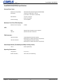
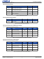
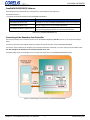
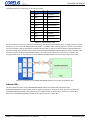
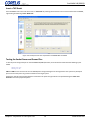
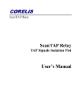
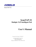
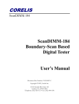
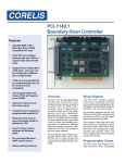
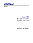
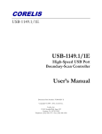
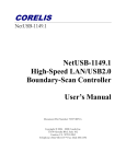
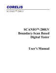
ScanDIMM-240/DDR3/R
Boundary-Scan Based
Digital Tester
User's Manual
Document Part Number: 70404 Revision C
Copyright © Corelis 2010. All rights reserved.
Corelis
12607 Hiddencreek Way
Cerritos, CA 90703-2146
Telephone: (562) 926-6727
Fax: (562) 404-6196
www.corelis.com
ScanDIMM-240/DDR3/R
Table of Contents
Chapter 1: Product Overview . . . . . . . . . . . . . . . . . . . . . . . . . . . . . . . . . . . 1
Introduction . . . . . . . . . . . . . . . . . . . . . . . . . . . . . . . . . . . . . . . . . . . . . . . . . . . . 1
Features of the ScanDIMM-240/DDR3/R . . . . . . . . . . . . . . . . . . . . . . . . . . . . . . . . . . . . 1
ScanDIMM-240/DDR3/R Specifications . . . . . . . . . . . . . . . . . . . . . . . . . . . . . . . . . . . . . 2
Chapter 2: ScanDIMM-240/DDR3/R Installation . . . . . . . . . . . . . . . . . . . . . . . . 4
Overview . . . . . . . . . . . . . . . . . . . .
ScanDIMM-240/DDR3/R Hardware . . . . . .
ScanDIMM-240/DDR3/R Software . . . . . .
Connecting to the Boundary-Scan Controller
Indicator LEDs . . . . . . . . . . . . . . . . . .
Mating Connectors . . . . . . . . . . . . . . .
Accessories . . . . . . . . . . . . . . . . . . .
.
.
.
.
.
.
.
.
.
.
.
.
.
.
.
.
.
.
.
.
.
.
.
.
.
.
.
.
.
.
.
.
.
.
.
.
.
.
.
.
.
.
.
.
.
.
.
.
.
.
.
.
.
.
.
.
.
.
.
.
.
.
.
.
.
.
.
.
.
.
.
.
.
.
.
.
.
.
.
.
.
.
.
.
.
.
.
.
.
.
.
.
.
.
.
.
.
.
.
.
.
.
.
.
.
.
.
.
.
.
.
.
.
.
.
.
.
.
.
.
.
.
.
.
.
.
.
.
.
.
.
.
.
.
.
.
.
.
.
.
.
.
.
.
.
.
.
.
.
.
.
.
.
.
.
.
.
.
.
.
.
.
.
.
.
.
.
.
.
.
.
.
.
.
.
.
.
.
.
.
.
.
.
.
.
.
.
.
.
.
.
.
.
.
.
.
.
.
.
.
.
.
.
.
.
.
.
.
.
.
.
.
.
.
.
.
.
.
.
.
.
.
.
.
.4
.4
.5
.5
.6
.7
.7
Chapter 3: Preparation of Test Input Files . . . . . . . . . . . . . . . . . . . . . . . . . . . . 8
Overview . . . . . . . . . . . . . . . . . . . . . . . . . . . . . . . . . . . . . . . . . . . . . . . . . . . . . 8
Preparation . . . . . . . . . . . . . . . . . . . . . . . . . . . . . . . . . . . . . . . . . . . . . . . . . . . . 8
Add the ScanDIMM BSDL File . . . . . . . . . . . . . . . . . . . . . . . . . . . . . . . . . . . . . . . . . . 8
Add BSDL Files Dialog . . . . . . . . . . . . . . . . . . . . . . . . . . . . . . . . . . . . . . . . . . . . . . . 9
TAP Pins Not Found in Netlist Warning (Safe to Ignore) . . . . . . . . . . . . . . . . . . . . . . . . . . . . 9
Insert a TAP Break . . . . . . . . . . . . . . . . . . . . . . . . . . . . . . . . . . . . . . . . . . . . . . . . 10
Testing the Socket Power and Ground Pins . . . . . . . . . . . . . . . . . . . . . . . . . . . . . . . . . . 10
Chapter 4: Executing Selftest . . . . . . . . . . . . . . . . . . . . . . . . . . . . . . . . . . 11
Overview . . . . . . . . . . . . . . . . . . . . . . . . . . . . . . . . . . . . . . . . . . . . . . . . . . . . . 11
Infrastructure Test . . . . . . . . . . . . . . . . . . . . . . . . . . . . . . . . . . . . . . . . . . . . . . . 11
Steps . . . . . . . . . . . . . . . . . . . . . . . . . . . . . . . . . . . . . . . . . . . . . . . . . . . . . . . 11
Chapter 5: Troubleshooting . . . . . . . . . . . . . . . . . . . . . . . . . . . . . . . . . . . 13
Overview . . . . . . . . . . . . . . . . . . . . . . . . . . . . . . . . . . . . . . . . . . . . . . . . . . . . . 13
Notes . . . . . . . . . . . . . . . . . . . . . . . . . . . . . . . . . . . . . . . . . . . . . . . . . . . . . . . 13
Chapter 6: Legal and Contact Information . . . . . . . . . . . . . . . . . . . . . . . . . . . 14
Table of Contents
i
www.corelis.com
ScanDIMM-240/DDR3/R
Chapter 1:
Product Overview
Introduction
The ScanDIMM-240/DDR3/R Digital Tester module provides an easy-to-use method for structurally testing 240-pin Registered
Dual Inline Memory Module (DIMM) sockets. Through the use of boundary-scan technology, the ScanDIMM-240/DDR3/R Digital
Tester provides 232 fully bi-directional test signals. A Boundary-Scan Test Access Port (TAP) connects to a host computer, which
provides virtually unlimited memory depth for testing each of the DIMM socket pins. The 240-pin sockets are often used for
Double Data Rate Dynamic Random Access Memory (DDR3 SDRAM) modules. The ScanDIMM-240/DDR3/R offers an accurate and
easy-to-use mechanical and electrical solution for connecting test equipment to DIMM sockets.
Features of the ScanDIMM-240/DDR3/R
• Tests 240-pin Registered DDR3 DIMM sockets for opens and shorts
• Tests for opens on the socket's power and ground pins
• 1.5V DIMM interface, 3.3V tolerant
• 1.8V TAP interface, 3.3V tolerant
• LEDs indicate power status and whether an active TAP connection is present
• Compatible with the Corelis ScanExpress boundary-scan test development tools and other third party software
The figure below shows the ScanDIMM-240/DDR3/R module with Pin 1 of the TAP IN connector identified.
Figure 1-1. ScanDIMM-240/DDR3/R module (top view)
Chapter 1: Product Overview
1
www.corelis.com
ScanDIMM-240/DDR3/R
ScanDIMM-240/DDR3/R Specifications
Size and Form Factor
Mechanical Compatibility
JEDEC MO-269F (240-pin Registered DDR3 DIMM)
Dimensions
133.35 mm x 30.00 mm ± 0.15 mm
[5.25 inches x 1.25 inches ± 0.01 inches]
PCB thickness
1.27 mm ± 0.10 mm
[0.05 ± 0.01 inches]
Connector Keying
1.5V-compatible
Maximum Test Clock (TCK) Frequency
Maximum TCK Frequency
25 MHz
PWR
Indicates the 1.5V power source is present
TAP ON
Indicates the TAP is connected
LEDs
TAP Connectors
TAP IN Connector
10-pin Single Row 0.100-inch spacing
(Samtec part no. TSM-110-01-G-SH or equivalent)
TAP OUT Connector
10-pin Single Row 0.100-inch spacing
(Samtec part no. TSM-110-01-G-SH or equivalent)
Power Requirements (Provided by the 240-pin mating socket)
1.50 V
0.250 A (Maximum)
Operating Environment
Temperature
0° C to 55° C
Relative Humidity
10% to 90%, non-condensing
Chapter 1: Product Overview
2
www.corelis.com
ScanDIMM-240/DDR3/R
Absolute Maximum Ratings
Symbol
Description
Value
Units
VCC
Supply voltage relative to ground
-0.5 to 2.0
V
VIN
Input voltage relative to ground
-0.5 to 4.0
V
TSTG
Storage Temperature (ambient)
-65 to +150
°C
+150
°C
TJ
Junction Temperature
Table 1-9. Absolute Maximum Ratings
Recommended Operating Conditions
Symbol
VCC
Parameter
Min
Max
Units
Supply voltage
1.4
1.6
V
Typical
Max
Units
Table 1-10. Recommended Operating Conditions
DC Electrical Characteristics (DIMM Socket Interface)
(1.5V DC Over Recommended Operating Conditions)
Symbol
Parameter
VIH
High level input voltage
0.98
3.9
V
VIL
Low level input voltage
-0.3
0.53
V
VOH
High level output voltage
1.05
-
V
VOL
Low level output voltage
-
0.4
V
Table 1-11. DC Electrical Characteristics (DIMM Socket Interface)
DC Electrical Characteristics (JTAG Interface)
(1.8V DC Over Recommended Operating Conditions)
Symbol
Parameter
Typical
Max
Units
VIH
High level input voltage
1.17
1.5
V
VIL
Low level input voltage
-0.3
0.63
V
VOH
High level output voltage
1.35
-
V
VOL
Low level output voltage
-
0.45
V
Table 1-12. DC Electrical Characteristics (JTAG Interface)
Chapter 1: Product Overview
3
www.corelis.com
ScanDIMM-240/DDR3/R
Chapter 2:
ScanDIMM-240/DDR3/R Installation
Overview
To ensure reliable operation of the ScanDIMM-240/DDR3/R, it is important to connect it properly to both the Corelis
boundary-scan controller and the 240-pin DDR3 DIMM socket on the unit under test (UUT).
ScanDIMM-240/DDR3/R Hardware
The ScanDIMM-240/DDR3/R product consists of the following components:
• ScanDIMM-240/DDR3/R, Corelis P/N 10407
• User's Manual, Corelis P/N 70404
• Host Adapter Cable, 10-pin, Corelis P/N 15336
• TAP OUT to TAP IN daisy-chain cable, 2" long, 10-pin 1:1, Corelis P/N 15337
The files related to the ScanDIMM-240/DDR3/R are installed by the ScanExpress installer.
Ensure that all materials listed are present and free from visible damage or defects before proceeding. If anything appears to be
missing or damaged, contact Corelis at the number listed on the title page immediately.
The figure below shows the ScanDIMM-240/DDR3/R and the cables that are included with the product.
Figure 2-1. ScanDIMM-240/DDR3/R and Cable Accessories
Chapter 2: ScanDIMM-240/DDR3/R Installation
4
www.corelis.com
ScanDIMM-240/DDR3/R
ScanDIMM-240/DDR3/R Software
The ScanExpress CD installs the files to a subdirectory of the ScanExpress TPG application.
The default location is:
"C:\Program Files\Corelis\ScanExpressTPG\ScanDIMM-240-DDR3-R".
Filename
Description
ScanDIMM-240-DDR3-R.bsd
The BSDL file for the ScanDIMM-240/DDR3/R Boundary-Scan component
ScanDIMM-240-DDR3-R.top
Sample topology file for the ScanDIMM-240/DDR3/R
ScanDIMM-240-DDR3-R_Selftest_inf.cvf
An infrastructure test for a single ScanDIMM-240/DDR3/R.
It is used with ScanExpress Runner as a basic functionality check
Table 2-13. ScanDIMM-240/DDR3/R Files
Connecting to the Boundary-Scan Controller
The external boundary-scan controller connects to the ScanDIMM-240/DDR3/R TAP IN connector via the 10-pin Host Adapter
Cable.
Connect one end of the Host Adapter Cable P/N 15336 to the TAP IN connector of the ScanDIMM-240/DDR3/R.
Connect the 10-pin cable from the boundary-scan controller (ScanTAP-4, ScanTAP-8, etc.) to the other end of the adapter cable.
The TAP Voltage for the boundary-scan controller should be set to 1.8V
The figure below shows a block diagram for the a typical TAP connection to a ScanDIMM-240/DDR3/R module.
Figure 2-2. Block Diagram of Connection to a ScanDIMM-240/DDR3/R
Chapter 2: ScanDIMM-240/DDR3/R Installation
5
www.corelis.com
ScanDIMM-240/DDR3/R
This table shows the pin assignments for the TAP IN connector.
Pin
Signal Name
I/O
Description
1
TRST*
In
Test Reset
2
GND
3
TDI
4
GND
5
TDO
6
GND
7
TMS
8
GND
9
TCK
10
GND
Ground
In
Test Data In
Ground
Out
Test Data Out
Ground
In
Test Mode Select
Ground
In
Test Clock
Ground
Table 2-14. TAP IN Connection List
The TAP IN connector conforms to the popular Corelis 10-pin TAP connector pinout except that it is a single row (10 x 1) instead
of dual row (5 x 2). The Host TAP Adapter Cable P/N 15336 is a 1:1 adapter cable. The pin assignment is standard, connecting to
any Corelis controller using the appropriate standard 10-pin TAP cable. It is best to use the PCI-1149.1/Turbo equipped with a
ScanTAP-4 Intelligent Pod, with one TAP connected to the ScanDIMM-240/DDR3/R and with additional TAP(s) connected to the
UUT. Other Corelis controllers like the NetUSB-1149.1/E can also be used so that the UUT can connect on a separate TAP.
The figure below shows the TAP connections for a ScanDIMM-240/DDR3/R module on TAP1 and the Target UUT on TAP2.
Figure 2-3. Connection of a ScanDIMM-240/DDR3/R Module and the Target using Separate TAPs
Indicator LEDs
Two LEDs indicate the status of the ScanDIMM-240/DDR3/R module. D1 is labeled PWR. It illuminates if the
ScanDIMM-240/DDR3/R is receiving power from the target (through pins 57, 60 and 176). If the LED is not illuminated, the
ScanDIMM-240/DDR3/R module is not powered up. D2 is labeled TAP ON. It indicates that a connection to a controller is
detected. The ScanDIMM-240/DDR3/R module will not operate unless D2 is illuminated.
Chapter 2: ScanDIMM-240/DDR3/R Installation
6
www.corelis.com
ScanDIMM-240/DDR3/R
Mating Connectors
The table below shows the mating connectors needed to make cables for the Boundary-Scan connector.
Reference
Description
TAP IN to TAP OUT
Host TAP Adapter Plug
Host TAP Adapter Socket
(Connects with Target)
Manufacturer
Part Number
10-pin 0.1 in. single row connector
Molex
50-57-9010
Crimp Terminals
Molex
16-02-0097
10-pin IDC Plug
3M
4610-6351
Strain Relief
3M
3448-3010
10-pin IDC Socket
3M
3473-6610
Strain Relief
3M
3448-3010
Table 2-15. Mating Connectors for the ScanDIMM-240/DDR3/R
Accessories
Additional TAP Adapter Cables (P/N 15336) can be ordered from Corelis:
Description
10-pin dual row IDC plug to
10 pin single row 1:1 cable
Corelis Part Number
Other Part Number
15336
Custom
Table 2-16. Cable Accessories for the ScanDIMM-240/DDR3/R
Chapter 2: ScanDIMM-240/DDR3/R Installation
7
www.corelis.com
ScanDIMM-240/DDR3/R
Chapter 3:
Preparation of Test Input Files
Overview
The ScanDIMM-240/DDR3/R integrates easily with a boundary-scan test plan. When the ScanDIMM-240/DDR3/R is installed in a
socket, the socket behaves like a boundary-scan component. Once the ScanDIMM-240/DDR3/R is plugged into the socket on the
target board, the boundary-scan test system will automatically test the socket. However, regeneration of the boundary-scan tests
with ScanExpress TPG is required.
Preparation
Copy the provided BSDL file to your local project directory.
Add the ScanDIMM BSDL File
While in the "Preparation:BSDL Files" stage of ScanExpress TPG, click "Add..." to launch the "Add BSDL Files" dialog.
Figure 3-1. ScanExpress TPG Test Preparation: Select BSDL Files
Chapter 3: Preparation of Test Input Files
8
www.corelis.com
ScanDIMM-240/DDR3/R
Add BSDL Files Dialog
Figure 3-2. Add BSDL Files Dialog
Uncheck the box "Show Only Devices Connected to JTAG Signals"
Select the Device that corresponds to the DIMM socket on the board in the left pane.
Select the BSDL File for the ScanDIMM-240-DDR3-R in the right pane.
Click "Add".
Click "Close" to exit the Add BSDL Files dialog.
TAP Pins Not Found in Netlist Warning (Safe to Ignore)
In some cases a popup message may appear that indicates that the ScanDIMM TAP pins are not found in the netlist. The TAP
connection between the boundary-scan controller and ScanDIMM module won't be in the board netlist and this warning is safe to
ignore.
Figure 3-3. TAP Pins Not Found in Netlist Warning (Safe to Ignore)
Chapter 3: Preparation of Test Input Files
9
www.corelis.com
ScanDIMM-240/DDR3/R
Insert a TAP Break
The ScanDIMM is now in the scan chain. Insert a "TAP Break" by selecting the last device in the scan chain before the ScanDIMM,
right clicking and selecting "Insert TAP Break"
Figure 3-4. ScanExpress TPG Test Preparation: ScanDIMM BSDL File Added
Testing the Socket Power and Ground Pins
To test the power and ground pins on the ScanDIMM-240/DDR3/R socket, the constraint file should have the following syntax
added:
SENSE_HIGH VDD
SENSE_LOW GND
VDD and GND are the net names of the 1.5V SDRAM power and ground signals on the target board. This syntax may already be
present to test other power or ground connections in the target system.
ScanExpress TPG will automatically add these constraints if the power and ground nets are specified during the Power and
Ground screen of the preparation phase.
Chapter 3: Preparation of Test Input Files
10
www.corelis.com
ScanDIMM-240/DDR3/R
Chapter 4:
Executing Selftest
Overview
ScanExpress Runner (sold separately) can load and run the compact vector file, ScanDIMM-240-DDR3-R_Selftest_inf.cvf, and
quickly verify that the ScanDIMM-240/DDR3/R is functional. Both the ScanExpress Runner software and a Corelis Boundary-Scan
controller such as the PCI-1149.1/Turbo are required to execute this file.
Infrastructure Test
The infrastructure test verifies the TAP connection between the controller and the ScanDIMM-240/DDR3/R. It also verifies that
the boundary-scan infrastructure of the device on the ScanDIMM-240/DDR3/R is fully functional. The infrastructure test requires
a Corelis Boundary-Scan controller, a ScanDIMM-240/DDR3/R unit and a Host TAP cable (P/N 15336). The following steps execute
an infrastructure test.
Steps
1. Remove any memory modules from the Unit Under Test (UUT) DIMM socket(s) to be tested.
2. Install the ScanDIMM-240/DDR3/R in the socket.
3. Connect the Host TAP Adapter cable P/N 15336 to the "TAP IN" connector on the ScanDIMM-240/DDR3/R.
4. Connect the 10-pin TAP cable from the external controller to the other end of the Host TAP Adapter cable.
5. Apply power to the UUT.
6. Make sure that both LEDs on the ScanDIMM-240/DDR3/R illuminate.
7. Double-click on the ScanExpress Runner Icon.
8. Select New Test Plan from the File menu and click on the Add button.
9. With the file browser, find and select the "ScanDIMM-240-DDR3-R_Selftest_inf.cvf" file. Click OK.
10. Select Controller from the Setup menu, then choose the appropriate Boundary-Scan controller.
11. Set the TCK frequency to 1 MHz and the TAP voltage to 1.8V.
12. Select Run Test. The test should run and pass.
Chapter 4: Executing Selftest
11
www.corelis.com
ScanDIMM-240/DDR3/R
The figure below shows a passing infrastructure test.
Figure 4-1. ScanExpress Runner Infrastructure Test
Chapter 4: Executing Selftest
12
www.corelis.com
ScanDIMM-240/DDR3/R
Chapter 5:
Troubleshooting
Overview
Use the following general guidelines to troubleshoot problems when the ScanDIMM-240/DDR3/R is added to the test system.
1. Make sure the ScanDIMM-240/DDR3/R's TAP Voltage is set to 1.8V
2. Make sure power is being supplied to the ScanDIMM-240/DDR3/R, the boundary-scan controller, and the target. The
ScanDIMM-240/DDR3/R's green LEDs will be illuminated if power (1.5V) is being supplied to the DIMM socket and the
boundary-scan controller is connected.
3. Run the provided self-test and make sure that it passes.
4. Reduce the TCK (test clock) frequency to 1 MHz. The TCK frequency can be set too high for the scan chain and
sometimes using a lower frequency will allow the test steps to pass. Once the scan chain is known to be stable, then the TCK
frequency can be increased to the maximum frequency that will allow the test steps to pass.
Notes
1. DDR3 modules are not backwards compatible with DDR2 modules and DDR3 modules will not fit into DDR2 sockets;
forcing them can damage the ScanDIMM and/or the board.
Chapter 5: Troubleshooting
13
www.corelis.com
ScanDIMM-240/DDR3/R
Chapter 6:
Legal and Contact Information
PRINTING HISTORY
Revision A, January 2010
Revision B, March 2010
Revision C, May 2010
GENERAL NOTICE
Information contained in this document is subject to change without notice. CORELIS shall not be liable for errors contained
herein for incidental or consequential damages in connection with the furnishing, performance, or use of material contained in
this manual.
This document contains proprietary information that is protected by copyright. All rights reserved. No part of this document may
be reproduced or translated to other languages without the prior written consent of CORELIS. This manual is a CORELIS
proprietary document and may not be transferred to another party without the prior written permission of CORELIS.
CORELIS assumes no responsibility for the use of or reliability of its software on equipment that is not furnished by CORELIS.
ENVIRONMENTAL NOTICE
This product must be disposed of in accordance with the WEEE directive.
TRADEMARK NOTICE
ScanExpress and ScanDIMM are trademarks of Corelis Inc.
Other products and services named in this manual are trademarks or registered trademarks of their respective companies. All
trademarks and registered trademarks in this manual are the property of their respective holders.
PRODUCT WARRANTY
For product warranty and software maintenance information, see the PRODUCT WARRANTY AND SOFTWARE MAINTENANCE
POLICY statement included with your product shipment.
EXCLUSIVE REMEDIES
THE REMEDIES CONTAINED HEREIN ARE THE CUSTOMER'S SOLE AND EXCLUSIVE REMEDIES. CORELIS SHALL NOT BE LIABLE FOR
ANY DIRECT, INDIRECT, SPECIAL, INCIDENTAL, OR CONSEQUENTIAL DAMAGES, WHETHER BASED ON CONTRACT, TORT, OR ANY
OTHER LEGAL THEORY. Product maintenance agreements and other customer assistance agreements are available for Corelis
products. For assistance, contact your nearest Corelis Sales and Service Office.
RETURN POLICY
No items returned to CORELIS for warranty, service, or any other reason shall be accepted unless first authorized by CORELIS,
either direct or through its authorized sales representatives. All returned items must be shipped pre-paid and clearly display a
Return Merchandise Authorization (RMA) number on the shipping carton. Freight collect items will NOT be accepted.
Customers or authorized sales representatives must first contact CORELIS with notice of request for return of merchandise.
RMA's can only originate from CORELIS. If authorization is granted, an RMA number will be forwarded to the customer either
directly or through its authorized sales representative.
Chapter 6: Legal and Contact Information
14
www.corelis.com
ScanDIMM-240/DDR3/R
CONTACT INFORMATION
For sales inquiries, please contact [email protected].
For any support related questions, please enter a support request at www.corelis.com/support or email [email protected].
For more information about other products and services that Corelis offers, please visit www.corelis.com.
Chapter 6: Legal and Contact Information
15
www.corelis.com