1
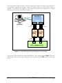
CORELIS
ScanTAP Relay
ScanTAP Relay
TAP Signals Isolation Pod
User’s Manual
CORELIS
ScanTAP Relay
ScanTAP Relay
TAP Signals Isolation Pod
User’s Manual
Document Part Number: 70359 Revision B
Copyright © 2004 Corelis Inc.
13100 Alondra Blvd. Suite 102
Cerritos, CA 90703-2262
Telephone: (562) 926-6727 • Fax: (562) 404-6196
Preface
PRINTING HISTORY
New editions are complete revisions of the manual. Update packages, which are issued between
editions, contain additional and replacement pages to be merged into the manual by the customer.
The dates on the title page change only when a new edition is published.
A software code may be printed before the date; this indicates the version of the software product at
the time the manual or update was issued. Many product updates and fixes do not require manual
changes and, conversely, manual corrections may be done without accompanying product changes.
Therefore, do not expect a one to one correspondence between product updates and manual
updates.
Revision A, April 2004
Revision B, February 2011
GENERAL NOTICE
Information contained in this document is subject to change without notice. CORELIS shall not be
liable for errors contained herein for incidental or consequential damages in connection with the
furnishing, performance, or use of material contained in this manual. This document contains
proprietary information, which is protected by copyright. All rights reserved. No part of this
document may be reproduced or translated to other languages without the prior written consent of
CORELIS.
CORELIS assumes no responsibility for the use of or reliability of its software on equipment that is
not furnished by CORELIS.
i
PRODUCT WARRANTY
For product warranty and software maintenance information, see the PRODUCT WARRANTY
AND SOFTWARE MAINTENANCE POLICY statement included with your product shipment.
EXCLUSIVE REMEDIES
THE REMEDIES CONTAINED HEREIN ARE THE CUSTOMER'S SOLE AND
EXCLUSIVE REMEDIES. CORELIS SHALL NOT BE LIABLE FOR ANY DIRECT,
INDIRECT, SPECIAL, INCIDENTAL, OR CONSEQUENTIAL DAMAGES, WHETHER
BASED ON CONTRACT, TORT, OR ANY OTHER LEGAL THEORY.
Product maintenance agreements and other customer assistance agreements are available for Corelis
products. For assistance, contact your nearest Corelis Sales and Service Office.
RETURN POLICY
No items returned to CORELIS for warranty, service, or any other reason shall be accepted unless
first authorized by CORELIS, either direct or through its authorized sales representatives. All
returned items must be shipped pre-paid and clearly display a Returned Merchandise Authorization
(RMA) number on the shipping carton. Freight collect items will NOT be accepted. Customers or
authorized sales representatives must first contact CORELIS with notice of request for return of
merchandise. RMA's can only originate from CORELIS. If authorization is granted, an RMA
number will be forwarded to the customer either directly or through its authorized sales
representative.
CONTACT INFORMATION
For sales inquiries, please contact [email protected].
For any support related questions, please enter a support request at www.corelis.com/support or
email [email protected].
For more information about other products and services that Corelis offers, please visit
www.corelis.com.
ii
Table of Contents
CHAPTER 1 PRODUCT OVERVIEW ....................................................... 1-1
Introduction ............................................................................................................................................................. 1-1
ScanTAP Relay Specifications ................................................................................................................................ 1-2
CHAPTER 2 SCANTAP RELAY INSTALLATION AND USAGE ............ 2-1
Connecting to the Host Controller ......................................................................................................................... 2-3
Connecting to the Target......................................................................................................................................... 2-3
ScanTAP Relay LED ............................................................................................................................................... 2-5
iii
List of Figures
Figure 1-1.
Figure 2-1.
Figure 2-2.
Figure 2-3.
Figure 2-4.
Figure 2-5.
iv
ScanTAP Relay ...................................................................................................................................... 1-1
ScanTAP Relay Connection Diagram (2 Units shown) ......................................................................... 2-2
20-Pin TAP Host Connector (top view) ................................................................................................. 2-3
20-Pin TAP Target Connector (top view) .............................................................................................. 2-3
ScanPlus Runner Setup Menu................................................................................................................ 2-5
Parallel Output Configuration Dialog .................................................................................................. 2-5
List of Tables
Table 2-1. 20 Pin Connector Pinout ......................................................................................................................... 2-4
v
Chapter 1
Product Overview
Introduction
The ScanTAP Relay pod is an add-on accessory that contains electro-mechanical relays for engaging
and dis-engaging boundary-scan Test Access Port (TAP). The ScanTAP Relay pod is operated
under host software control and provides electrical isolation of all the TAP signals, including
Ground. It is compatible with the various Corelis ScanTAP intelligent modules and is mostly used
when integrating the Corelis boundary-scan test tools with in-circuit testers such as the Agilent 3070.
By coupling the power of the ScanPlus boundary-scan tools with that of an in-circuit tester (ICT)
such as the Agilent 3070 or the Teradyne Test Station, a complete, integrated solution is now
available that offers the best advantages of both technologies.
Boundary-scan (JTAG) operates as the complementary companion to the ICT. Boundary-scan is the
preferred solution for testing areas of printed circuit board assemblies that are difficult to access due
to physical space constraints and lack of physical access, which is often due to fine pitch
components such as Ball Grid Array (BGA) devices. Additionally, the ICT is able to check the nonboundary-scan compatible portion of the unit under test (UUT) such as analog circuitry.
Integrating the Corelis ScanPlus boundary-scan tools with the Agilent and/or the Teradyne ICT into
a single test system forms a powerful and cost-effective solution that virtually eliminates each of the
obstacles that are presented to the individual test technologies. By utilizing the benefits of both
boundary-scan and the ICT, complete test procedures can be created in a minimal time frame that
provide outstanding test coverage of the entire printed circuit board assembly.
Before power is applied to the target by the ICT during testing it runs several diagnostic checks. To
prevent ground loops from disturbing unpowered testing, the boundary-scan TAP signals are
connected through the ScanTAP Relay module. The ScanTAP Relay utilizes electro-mechanical
relays to physically disconnect and isolate the TAP and ground signals so they do not interfere with
the ICT power-off UUT tests. The ScanTAP Relay module is shown in Figure 1-1.
Figure 1-1. ScanTAP Relay
Product Overview
1-1
ScanTAP Relay Specifications
Controller Interface
Host Connector
20-pin header, AMP part no. 104130-4 or equivalent
Host Cable Length
20-pin to 20-pin (12”), Corelis P/N 15312-2 (standard)
20-pin to 20-pin (8”), Corelis P/N 15312-1 (optional)
TAP Interface
TAP Connector
20-pin header, AMP part no. 104130-4 or equivalent
Mating TAP Connector
20-pin IDC (flat cable), 3M part no. 3421-6620 or equivalent
TAP Cable Length
20-pin to 20-pin (8”), Corelis P/N 15312-1 (optional)
20-pin to 20-pin (12”), Corelis P/N 15312-2 (standard)
20-pin to 10-pin (8”), Corelis P/N 15310-1 (optional)
20-pin to 10-pin (12”), Corelis P/N 15310-2 (optional)
20-pin to 16-pin (8”), Corelis P/N 15311-1 (optional)
20-pin to 16-pin (12”), Corelis P/N 15311-2 (optional)
Physical
Enclosure Dimensions
4.0 in. × 2.0 in. × 0.80 in.
Power Requirements
No external supply is needed
Power is provided by the host controller
(draws 25mA maximum at 2.5V)
Operating Environment
Temperature
Relative Humidity
0°C to 55°C
10% to 90%, non condensing
Storage Environment
Temperature
1-2
-40°C to 85°C
Product Overview
Chapter 2
ScanTAP Relay Installation and Usage
When you receive the ScanTAP Relay product it should contain the following items:
• ScanTAP Relay Module
• Host Cable, 20-pin to 20-pin Cable (12 inch), Corelis P/N 15312-2
• TAP Cable, 20-pin to 10-pin Cable (12 inch), Corelis P/N 15310-2
Please ensure that all materials listed are present and free from visible damage or defects before
proceeding. If anything appears to be missing or damaged, contact Corelis at the number listed
on the title page immediately.
NOTE: The actual hardware shipped with the ScanTAP Relay may vary depending on the
customer order.
When this manual was published, the following optional target interface TAP cables were available
from Corelis:
20-pin to 10-pin TAP cable (8”), Corelis P/N 15310-1
20-pin to 10-pin TAP cable (12”), Corelis P/N 15310-2
20-pin to 16-pin TAP cable (8”), Corelis P/N 15311-1
20-pin to 16-pin TAP cable (12”), Corelis P/N 15311-2
20-pin to 20-pin TAP cable (8”), Corelis P/N 15312-1
20-pin to 20-pin TAP cable (12”), Corelis P/N 15312-2
ScanTAP Relay Installation and Usage
2-1
The Corelis ScanTAP Relay module connects to the ScanTAP family of intelligent pods (ScanTAP4, ScanTAP-8, ScanTAP-32) through a 20-pin flat ribbon cable. No external power supply is
required - the ScanTAP pod supplies it. The connections between the components in a typical
boundary-scan system are shown below in Figure 2-1.
ScanTAP-4
(or ScanTAP-8)
(or ScanTAP-32)
Cable P/N 15339
TAP 1
Host
Computer
TAP 2
Cable
P/N 15312
Cable
P/N 15312
HOST
HOST
ScanTAP ScanTAP
Relay
Relay
TAP
TAP
TAP
Cable
P/N 15310
Cable
P/N 15310
TAP
TAP
UUT or Multiple UUTs
Figure 2-1. ScanTAP Relay Connection Diagram (2 Units shown)
There are two 20-pin connectors on the ScanTAP Relay. The connector marked Host connects to
the boundary-scan controller (ScanTAP pod) and the connector marked TAP connects to the target
(UUT).
2-2
ScanTAP Relay Installation and Usage
Connecting to the Host Controller
The Corelis ScanTAP Relay module connects to the ScanTAP family of intelligent pods (ScanTAP4, ScanTAP-8, ScanTAP-32) through a 20-pin flat ribbon cable. The top view of the 20-pin host
connector (0.100" x 0.100" spacing) is shown in Figure 2-2 below.
TRST* 1
2
GND
TDI
3
4
GND
TDO
5
6
GND
TMS
7
8
GND
TCK
9
10 GND
Write_Strobe* (GPIO1) 11
12 GND
Relay Enable* (GPIO2) 13
14 GND
Ready/Busy* (GPIO3) 15
16 GND
UUT Power Test Point
17
18 GND
2.5V Power Supply
19
20 GND
Figure 2-2. 20-Pin TAP Host Connector (top view)
Connecting to the Target
The ScanTAP Relay connects to the target via 10-pin, 16-pin or 20-pin flat cables, P/N 15310,
15311 or 15312. The top view of the 20-pin target connector (0.100” x 0.100” spacing) is shown in
Figure 2-3 below.
TRST* 1
2
GND
TDI
3
4
GND
TDO
5
6
GND
TMS
7
8
GND
TCK
9
10 GND
Write_Strobe* (GPIO1) 11
12 GND
N.C. 13
14 GND
Ready/Busy* (GPIO3) 15
16 GND
UUT Power Test Point
17
18 GND
N.C.
19
20 GND
Figure 2-3. 20-Pin TAP Target Connector (top view)
ScanTAP Relay Installation and Usage
2-3
The connector pin descriptions are shown in Table 2-1. The first 5 signals on pins 1 through 9 are
the standard IEEE-1149.1 signals. Corelis Flash Programming software supports two additional
signals: the external write strobe signal (Write_Strobe*) and the external Ready/Busy* signal.
The Write_Strobe* signal is active low and should be pulled up with a 1K resistor on the target
board. It needs to be logically OR-ed with the flash Write-Enable (WE*) signal so that assertion of
either the flash Write-Enable (WE*) signal or the external write strobe will assert the flash WE*
input.
The Ready/Busy* signal is an open-collector/open-drain signal which is directly tied to the same
signal(s) on the Flash device(s).
The signal Vcc1 (pin 17) is used to test a power supply rail of the UUT for shorts between power
and ground.
Pin
Host Signal
Target Signal
Direction
1
2
3
4
5
6
7
8
9
10
11
12
13
TRST*
GND
TDI
GND
TDO
GND
TMS
GND
TCK
GND
Write Strobe* (GPIO1)
GND
Relay Enable (GPIO2)
TRST*
GND
TDI
GND
TDO
GND
TMS
GND
TCK
GND
Write Strobe* (GPIO1)
GND
N.C.
Input to the UUT
14
15
16
17
18
19
GND
Ready/Busy* (GPIO3)
GND
VCC1
GND
2.5V
GND
Ready/Busy* (GPIO3)
GND
VCC1
GND
N.C.
20
GND
GND
Input to the UUT
Output of the UUT
Input to the UUT
Input to the UUT
Input to the UUT
Active high enables the
ScanTAP Relay
Output of the UUT
UUT Power Test Point
Power Supplied to
ScanTAP Relay
Table 2-1. 20 Pin Connector Pinout
2-4
ScanTAP Relay Installation and Usage
The internal relays are disabled (TAP and ground signals are disconnected) when GPIO2 (bit 1) is
“1”. The relays are enabled (TAP and ground signals are connected) when GPIO2 (bit 1) is “0”.
To setup the parallel I/O, go to the ScanPlus Runner or ScanExpress Runner main window. Select
Parallel I/O from the Setup menu as shown in Figure 2-4.
Figure 2-4. ScanPlus Runner Setup Menu
Check the box labeled “Set Initial Hex Value to:” and enter the hex value “0xFFFD” into the text
field. Configure the rest of the settings as shown in Figure 2-5. Please note that it is necessary to
wait a short amount of time (~10 ms) once the GPIO2 signal has been set for the relays to activate.
Figure 2-5. Parallel Output Configuration Dialog
ScanTAP Relay LED
The green LED on the top cover of the ScanTAP Relay will illuminate when the relays are enabled.
Note that the power to the ScanTAP-Relay is provided from the host adapter (PCI-1149.1/Turbo,
NetUSB-1149.1, etc.) via a current limiting fuse on the host adapter.
ScanTAP Relay Installation and Usage
2-5