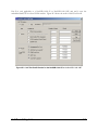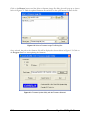
1
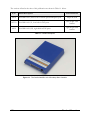
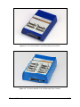
CORELIS
NetUSB-1149.1
NetUSB-1149.1
High-Speed LAN/USB2.0
Boundary-Scan Controller
User’s Manual
Document Part Number: 70337 REV L
Copyright © 2004 - 2008 Corelis Inc.
13100 Alondra Blvd. Suite 102
Cerritos, CA 90703-2262
Telephone: (562) 926-6727 • Fax: (562) 404-6196
Preface
PRINTING HISTORY
New editions are complete revisions of the manual. Update packages, which are issued between
editions, contain additional and replacement pages to be merged into the manual by the customer.
The dates on the title page change only when a new edition is published.
A software code may be printed before the date; this indicates the version of the software product at
the time the manual or update was issued. Many product updates and fixes do not require manual
changes and, conversely, manual corrections may be done without accompanying product changes.
Therefore, do not expect a one to one correspondence between product updates and manual
updates.
Edition 9, February 2006
Edition 10, June 2007
Edition 11, March 2008
Edition 12, February 2011
GENERAL NOTICE
Information contained in this document is subject to change without notice. CORELIS shall not be
liable for errors contained herein for incidental or consequential damages in connection with the
furnishing, performance, or use of material contained in this manual. This document contains
proprietary information, which is protected by copyright. All rights reserved. No part of this
document may be reproduced or translated to other languages without the prior written consent of
CORELIS.
CORELIS assumes no responsibility for the use of or reliability of its software on equipment that is
not furnished by CORELIS.
The firmware inside the NetUSB-1149.1 includes compiled source code licensed from the Free
Software Foundation. As part of Corelis conformance with copyrights law and in accordance with
the General Public License of the Free Software Foundation the source code is available for general
distribution for a nominal fee. You can order the source code as is, without any expressed or
implied warranty, directly from Corelis for a nominal distribution and handling fee of $150, F.O.B.
Cerritos, CA. This offer is valid until 12-31-2008.
ENVIRONMENTAL NOTICE
This product must be disposed of in accordance with the WEEE directive.
TRADEMARK NOTICE
All products and services named in this book are trademarks or registered trademarks of their
respective companies. All trademarks and registered trademarks in this book are the property of
their respective holders.
i
PRODUCT WARRANTY
For product warranty and software maintenance information, see the PRODUCT WARRANTY
AND SOFTWARE MAINTENANCE POLICY statement included with your product shipment.
EXCLUSIVE REMEDIES
THE REMEDIES CONTAINED HEREIN ARE THE CUSTOMER'S SOLE AND
EXCLUSIVE REMEDIES. CORELIS SHALL NOT BE LIABLE FOR ANY DIRECT,
INDIRECT, SPECIAL, INCIDENTAL, OR CONSEQUENTIAL DAMAGES, WHETHER
BASED ON CONTRACT, TORT, OR ANY OTHER LEGAL THEORY.
Product maintenance agreements and other customer assistance agreements are available for Corelis
products. For assistance, contact your nearest Corelis Sales and Service Office.
RETURN POLICY
No items returned to CORELIS for warranty, service, or any other reason shall be accepted unless
first authorized by CORELIS, either direct or through its authorized sales representatives. All
returned items must be shipped pre-paid and clearly display a Returned Merchandise Authorization
(RMA) number on the shipping carton. Freight collect items will NOT be accepted. Customers or
authorized sales representatives must first contact CORELIS with notice of request for return of
merchandise. RMA's can only originate from CORELIS. If authorization is granted, an RMA
number will be forwarded to the customer either directly or through its authorized sales
representative.
CONTACT INFORMATION
For sales inquiries, please contact [email protected].
For any support related questions, please enter a support request at www.corelis.com/support or
email [email protected].
For more information about other products and services that Corelis offers, please visit
www.corelis.com.
ii
Table of Contents
CHAPTER 1 PRODUCT OVERVIEW .......................................................................... 1-1
Introduction ................................................................................................................................................ 1-1
What Is IEEE Standard 1149.1? ................................................................................................................ 1-4
Features of the NetUSB-1149.1 ................................................................................................................. 1-4
Adjustable Voltage Interface ................................................................................................................................. 1-5
Discrete Input/Output Signals................................................................................................................................ 1-5
USB Port Interface................................................................................................................................................. 1-6
Ethernet Port Interface ........................................................................................................................................... 1-6
RS-232 Serial Maintenance Port Interface ............................................................................................................ 1-6
Programmable Clocks............................................................................................................................................ 1-7
Other Features of the TAP Ports ................................................................................................................ 1-7
Specifications ............................................................................................................................................. 1-8
CHAPTER 2 NETUSB-1149.1 INSTALLATION .......................................................... 2-1
Software Installation First! ........................................................................................................................ 2-2
Hardware Installation ................................................................................................................................. 2-3
CHAPTER 3 CONNECTING TO THE TARGET .......................................................... 3-1
Connecting to the Target ............................................................................................................................ 3-1
Target Connector Pin Assignments............................................................................................................ 3-2
CHAPTER 4 USING NETUSB-1149.1 WITH SCANEXPRESS ................................... 4-1
Hardware Setup .......................................................................................................................................... 4-1
Using NetUSB-1149.1 Family with ScanExpress Tools over a Network Connection .............................. 4-1
Using NetUSB-1149.1 Family with ScanExpress Tools over a USB Connection .................................... 4-3
CHAPTER 5 THIRD PARTY APPLICATION INTERFACE ......................................... 5-1
Using NetUSB-1149.1 with ScanExpress Runner Command-line ............................................................ 5-1
APPENDIX A RECOMMENDED TARGET CONNECTORS ...................................... A-1
10-pin TAP Connector .............................................................................................................................. A-1
16-pin Flash Programming TAP Connector ............................................................................................. A-4
20-pin Flash Programming TAP Connector ............................................................................................. A-7
APPENDIX B SELF TEST UTILITY SOFTWARE ...................................................... B-1
Self-Test .................................................................................................................................................... B-1
APPENDIX C FIRMWARE UPDATE UTILITY SOFTWARE ...................................... C-1
Firmware Update Utility ........................................................................................................................... C-1
iii
iv
List of Figures
Figure 1-1. The Corelis NetUSB-1149.1 Boundary-Scan Controller ....................................................................... 1-2
Figure 1-2. The Corelis NetUSB-1149.1/E Boundary-Scan Controller ................................................................... 1-3
Figure 1-3. The Corelis NetUSB-1149.1/SE Boundary-Scan Controller ................................................................. 1-3
Figure 1-4. Minimal Test Access Port (TAP) ........................................................................................................... 1-4
Figure 2-1. NetUSB-1149.1 Configuration Utility ................................................................................................... 2-4
Figure 4-1. Controller Configuration Screen ........................................................................................................... 4-1
Figure 4-2. NetUSB-1149.1 Setup Screen ................................................................................................................ 4-2
Figure 4-3. Incorrect Active POD Selected .............................................................................................................. 4-2
Figure 4-4. Advanced Configuration Setup Screen .................................................................................................. 4-3
Figure 4-5. NetUSB-1149.1 Setup Screen ................................................................................................................ 4-4
Figure 4-6. Incorrect Active POD Selected .............................................................................................................. 4-4
Figure 4-7. Advanced Configuration Setup Screen .................................................................................................. 4-5
Figure A-1. Standard 10-pin TAP connector (top view) ........................................................................................... A-1
Figure A-2. 10-pin TAP Connector Schematic ......................................................................................................... A-3
Figure A-3. Boundary-scan Flash Programming 16-pin TAP Connector (top view) ............................................... A-4
Figure A-4. 16-pin Flash Programming TAP Connector Schematics ...................................................................... A-6
Figure A-5. Boundary-scan Flash Programming 20-pin TAP Connector (top view) ............................................... A-7
Figure B-1. Self-Test Results for the NetUSB-1149.1/E and the NetUSB-1149.1/SE ............................................... B-1
Figure B-2. Self-Test Part A Results for the NetUSB-1149.1/E or the NetUSB-1149.1/SE ...................................... B-2
Figure B-3. Self-Test Part B Results for the NetUSB-1149.1/E or the NetUSB-1149.1/SE ...................................... B-3
Figure C-1. Firmware Update Utility for the NetUSB-1149.1 family ....................................................................... C-1
Figure C-2. Select a Firmware Image File Dialog Box ............................................................................................ C-2
Figure C-3. Firmware Update Utility with the Firmware Selected ........................................................................... C-2
Figure C-4. Firmware Update Confirmation Dialog ................................................................................................ C-3
Figure C-5. Firmware Update Progress Dialog ....................................................................................................... C-3
Figure C-6. Firmware Update Success Dialog ......................................................................................................... C-3
v
List of Tables
Table 1-1.
Table 1-2.
Table 1-3.
Table 1-4.
Table 1-5.
Table 1-6.
Table 1-7.
Table 3-1.
Table 5-1.
Table 5-2.
Table A-1.
Table A-2.
Table A-3.
Table A-4.
Table A-5.
Table A-6.
vi
Model Descriptions ................................................................................................................................. 1-2
Programmable TCK Frequencies............................................................................................................ 1-7
NetUSB-1149.1 SCSI Direct TAP Target Interface DC Characteristics ................................................. 1-9
NetUSB-1149.1/E TAPs Target Interface DC Characteristics .............................................................. 1-10
NetUSB-1149.1/SE TAPs Target Interface DC Characteristics ............................................................ 1-10
NetUSB-1149.1/E SPI Interface DC Characteristics ............................................................................ 1-11
NetUSB-1149.1/E I2C Interface DC Characteristics ............................................................................ 1-12
TAP Cable Target Pin Assignments ........................................................................................................ 3-2
NetUSB-1149.1/Net Controller Parameters ............................................................................................ 5-4
NetUSB-1149.1/USB Controller Parameters .......................................................................................... 5-7
Signal Description and Termination ....................................................................................................... A-2
Standard 10-Pin TAP Connector ............................................................................................................ A-2
Flash Programming TAP 16 Pin Connector ........................................................................................... A-5
Signal Description and Termination ....................................................................................................... A-5
Flash Programming TAP 20-pin Connector ........................................................................................... A-8
Signal Description and Termination ....................................................................................................... A-8
Chapter 1
Product Overview
Introduction
The NetUSB-1149.1, NetUSB-1149.1/E and NetUSB-1149.1/SE High-Speed Boundary-Scan
(JTAG) Controllers are members of the Corelis ScanPlus™ and ScanExpress™ family of scanbased test, analysis, and diagnostic tools. They are managed by a PC host, which is linked with
either a USB2.0 (compatible with USB1.1) interface, or over 10/100 Ethernet network. Under host
direction, the NetUSB-1149.1, NetUSB-1149.1/E and NetUSB-1149.1/SE test one or more IEEE
Standard 1149.1 compatible target board (UUT). The NetUSB-1149.1 family is designed to control
the operation of one or more IEEE Standard 1149.1 boundary-scan (JTAG) test access ports
(TAPs) by generating the proper signals as dictated by software. This provides stimulus and accepts
response signals of the attached customer target circuits, enabling their testing and/or programming.
This capability is supported by memory-behind-the-pin architecture driving scan operations at
continuous JTAG clock (TCK) speeds of up to 70 MHz.
The NetUSB-1149.1 family facilitates software-controlled boundary-scan operations per the IEEE
Standard 1149.1. It provides command visibility to the target’s Test Access Port (TAP), accessing
device internal registers and on-chip debugger, verifying PCB interconnects, performing functional
testing, and debug without manual probing. The JTAG interface provides access to internal device
functions that are not accessible via external probing, enabling fault isolation within the device itself.
The JTAG interface also enables programming target FLASH and CPLD devices, as well as data
downloading and uploading to and from the target memory devices.
Either of the NetUSB-1149.1 type controllers can also be used to perform microprocessor
emulation via that device’s JTAG port. This facilitates firmware development by providing singlestep, break, and content update/visibility access.
There are three models of this product. The basic NetUSB-1149.1 (no /E or /SE suffix) has
scanning access through a single SCSI II 68-pin connector. This supports a single direct target TAP
operation with the appropriate cable. With a different cable type, it implements the Corelis
ScanExpress expansion bus to operate a remote intelligent pods, such as the ScanTAP-4, ScanTAP8, ScanTAP-32, or ScanHUB (in turn accessing more of the ScanTAP intelligent pods). The
NetUSB-1149.1/E and NetUSB-1149.1/SE models are capable of scanning multiple TAPs
concurrently when used with the ScanExpress Runner software which is sold separately.
The NetUSB-1149.1/E model is similar to the NetUSB-1149.1 above, but has the equivalent of a
ScanTAP-4 remote pod built-in as an integral resource, enabling it to operate up to four boundaryscan TAPs simultaneously. Note that the external SCSI connector on this unit is not used and no
external ScanTAP pod is required.
The NetUSB-1149.1/SE model is similar to the NetUSB-1149.1/E except that it contains a built in
ScanTAP-8 pod as an integral resource, enabling it to operate up to eight target TAPs
simultaneously, with no other external equipment And therefore the NetUSB-1149.1/SE model
does not use the external SCSI connector.
Product Overview
1-1
The versions offered at the time of this publication are shown in Table 1-1 below.
P/N
Model Description
10338
NetUSB-1149.1, direct TAP or remote pod ScanExpress port
10337A
10339
Scan Connector
68-pin SCSI II
NetUSB-1149.1/E, four built-in TAP ports
four 20-pin TAP
headers
NetUSB-1149.1/SE, eight built-in TAP ports
eight 20-pin TAP
headers
Table 1-1. Model Descriptions
Figure 1-1. The Corelis NetUSB-1149.1 Boundary-Scan Controller
1-2
Product Overview
Figure 1-2. The Corelis NetUSB-1149.1/E Boundary-Scan Controller
Figure 1-3. The Corelis NetUSB-1149.1/SE Boundary-Scan Controller
Product Overview
1-3
What Is IEEE Standard 1149.1?
The IEEE Standard 1149.1 Test Access Port (TAP) and boundary-scan architecture enable control
of an IC, board, or system, via a standard four-signal interface. Each IEEE-1149.1 compliant IC
incorporates a feature known as boundary-scan, which ensures that a JTAG controller can control
and observe each functional pin of the IC via the JTAG interface. A controller can load test, debug,
or initialization patterns serially into the appropriate IC(s) via the IEEE-1149.1 TAP. Thus, even
with limited physical access, a user can observe or control IC, board, or system functions.
Two main elements comprise the IEEE Standard 1149.1 test Port: a Test Access Port (TAP), which
interfaces internal IC logic with the external world via a four-signal (optionally five-signal) Port as
shown in Figure 1-4, and a boundary-scan architecture, which defines standard boundary cells that
drive and receive data at the IC pins. IEEE Standard 1149.1 also defines both mandatory and
optional OPCODES and test features. The test Port signals are: Test Clock (TCK), Test Mode
Select (TMS), Test Data In (TDI), Test Data Out (TDO), and the optional Test Logic Reset (TRST).
The IEEE-1149.1 Test Access Port
Interface (TAP) consists of four
required signals:
TMS
Test Mode Select (TMS)
TCK
Test Clock (TCK)
TDI
Test Data In (TDI)
Test Data Out (TDO)
A fifth signal is defined as optional:
T
A
TDO
TRST*
P
Test Reset (TRST*)
Figure 1-4. Minimal Test Access Port (TAP)
Features of the NetUSB-1149.1
The Corelis NetUSB-1149.1 family includes the NetUSB-1149.1, NetUSB-1149.1/E and the
NetUSB-1149.1/SE models. It is a high performance boundary-scan test and programming
controller that can access devices, boards or systems compliant with IEEE Standard 1149.1. It has
two distinct host PC access ports for easy deployment, including USB 2.0 (also compatible with
USB 1.1) and Ethernet 10/100baseT, only one of which manages operations at a time. If a host
connection is made both at the Ethernet and USB ports, the USB access controls operation.
These scan controllers drive one or more JTAG boundary-scan chains (TAP), depending on module
type and/or attachment of external pods (ScanTAP-x). Included per TAP are a number of input
and/or output discrete signals available to test or control non-boundary-scan areas of the unit under
test (UUT) target. They facilitate non-scanned target FLASH write pulsing and FLASH ready/busy
line sensing to greatly reduce the scanning cycles required for such devices. With its softwarecontrolled voltage translating logic, the NetUSB-1149.1 family can test low voltage as well as
standard TTL/CMOS systems.
1-4
Product Overview
The NetUSB-1149.1 family contains several performance enhancing functional sections aimed at
increasing test vector throughput. Key elements include the TAP controller, and the memory
resources that support it. The large on-board memory provides scan data storage and can often
hold the data for an entire scan, maximizing performance and enabling real-time operations.
A test system accesses the TAP controller and its associated memory by host management
communications. This is supported by the high data rate of the USB 2.0 or Ethernet 10/100baseT
links, regardless of actual TCK test clock speeds. The ability to download information into these
memory elements decouples the scan operations from the host software. A state machine that
contains status and control registers accessible to the host controls all functions of the NetUSB1149.1 controllers.
The NetUSB-1149.1 family TAP controllers contain special autonomous hardware accelerator
mechanisms to greatly increase performance where scan patterns repeat numerous times. This
applies to target download/upload sequence loops, which convey large data blocks. As a result, time
consuming tasks such as flash programming and emulator data transfers are more efficient for a
given clock rate. This mechanism off-loads the host interaction requirements by generating repeated
vectors internally, using host pre-loaded memory information. After host initialization, this mode of
operation results in continuous, maximal scanning rates at all clock frequencies. The only exception
occurs when the target paces the sequence by indicating a non-ready completion of data transfer,
requiring a re-scan of the target’s status. When not in this special autonomous mode, the scan
stream bursts at the programmed TCK rate, as paced by the flow of vector bits from the host.
Another performance enhancement provides hardware expected-value verification of scanned-back
data at programmable chain positions. Thus, the target output stream is evaluated for each TAP
without host intervention and accompanying process delays. This also supports the above
autonomous operation enabling the scanning sequence to loop and rescan until the desired feedback
is supplied, without host intervention.
A programmable, time delay skew compensation mechanism supports the NetUSB-1149.1 family
high clock rates. This accommodates the returned target scan bit delays due to signal travel time
down and up the cables. It can also adjust for a target’s on-board TCK-to-TDO response delay.
An auxiliary feature of the NetUSB-1149.1 family is the target power-shorted detector for two
voltages. With the target un-powered, this mechanism effectively measures the impedance of the
target load for each of two possible connected voltages, determining if a short exists (some
unacceptably low impedance). If this impedance is less than about 1 ohm (about an 11 watt target
or more at 3.3V, for example), it is deemed shorted and reported to the user.
Adjustable Voltage Interface
The software-programmable voltage level of the discrete I/O and TAP interface can be set to any
voltage between 1.25 V and 3.30 V with 0.05V resolution .
Discrete Input/Output Signals
SCSI Connector Direct TAP Port
The NetUSB-1149.1 family offers 3 discrete input and 5 discrete output signals on the SCSI
connector (front panel). They are driven or sensed under host software control, in coordination
with the scanning operation. All of these signals track the software adjustable interface voltage level.
Product Overview
1-5
One of the discrete inputs is designated a FLASH ready/busy handshake input, enabling the direct
(non-scanned) pacing of device programming. This avoids the need to scan in this information,
speeding up the overall process.
One of the discrete outputs is dedicated as an external write pulse signal. This can reduce cycle
times by directly driving (non-scanned) the FLASH device, without the need to scan it out.
The other 4 outputs are generally useful for providing control functions on the user target system
such as reset, power control, and disable/enable signals for non-boundary-scan target devices.
Further, the additional 2 inputs enable host sensing of the target as a pacing method.
If open-collector mode is selected, the external write and two of the general discretes (porta_out0,
and porta_out1) operate that way, while the other two general discrete output will float. Otherwise,
all 5 outputs will operate as adjustable voltage totem-pole.
Built-in or Remote Pod TAP Ports
The NetUSB-1149.1 with an external pod (ScanTAP-x), the NetUSB-1149.1/E with 4 built-in TAP
ports or the NetUSB-1149.1/SE with 8 built-in TAP ports provide 3 discrete bi-directional
input/output signals. These are independently direction steer-able under software control, as well as
capable of open-collector (open-drain) drive operation. Here also, one can function as the FLASH
external write strobe and another as the FLASH ready/busy sense signal, as above, for accelerated
operations.
USB Port Interface
The NetUSB-1149.1 family USB interface complies with the version 2.0 standard with backward
compatibility to version 1.1 (excluding low speed). Speed adjustment is automatic per the standard.
The hot-plug feature of this standard is fully supported such that attachment is easily made to a
running PC, which will automatically sense its presence. For optimal performance, the user is
strongly recommended to utilize a host PC with a USB 2.0 port. This interface serves as one of two
host access points, only one of which operates the controller at a time.
Ethernet Port Interface
This serves as an alternate host access point to the USB interface. The NetUSB-1149.1 family
Ethernet interface supports 10/100baseT with automatic speed switching. It is IEEE 802.3u
100BASE-FX compatible.
RS-232 Serial Maintenance Port Interface
THIS IS FOR FACTORY USE ONLY …
NetUSB-1149.1 products.
As delivered, this port is disabled on all
The NetUSB-1149.1 family serial port is provided for trouble shooting purpose only at the factory.
During normal operation, users should not need to access this port. Its connector is a female DB9,
wired with a DTE pin-out. The default communications parameters are 115200 baud, 8 bits, no
parity, 1 stop bit, XON/XOFF flow control. This port should be connected to a PC on COM1
using a NULL modem cable.
1-6
Product Overview
Programmable Clocks
The NetUSB-1149.1 family’s programmable TCK output to the IEEE Standard 1149.1 compatible
target system can be generated with a wide range of frequencies using on-board clock generation
circuitry. A programmable Phase Locked Loop (PLL) and counter dividers enable both an agile and
fine resolution set of rates. See Table 1-2 for the set of programmable values.
TCK range (MHz)
Rate Resolution (MHz)
25 to 70
1.0
12.5 to 25.0
0.5
6.25 to 12.5
0.25
5.0 to 6.25
0.125
2.5 to 5.0
0.10
1.25 to 2.5
0.05
0.62 to 1.25
0.025
0.39 to 0.62
0.0156
0.05 to 0.39
0.05
Table 1-2. Programmable TCK Frequencies
Other Features of the TAP Ports
Besides the direct target TAP operation, NetUSB-1149.1 (not the NetUSB-1149.1/E or NetUSB1149.1/SE) can operate a remote pod, such as the Corelis ScanTAP-x or ScanHUB family. By
special differential signaling methods, and automatic propagation delay compensation, such remote
pods can employ cables up 30 feet in length, with no additional hardware, at full TCK rate
performance.
The 8 TAPs of the NetUSB-1149.1/SE, the 4 TAPs of the NetUSB-1149.1/E, or the remote pod
TAPs driven by the NetUSB-1149.1 can be programmed to daisy-chain sub-sets of the TAP ports
into single chains. During gang (concurrent) TAP operations, all targets can be scanned
simultaneously. While scanning, each TAP returns scanned in information that is compared against
expected patterns for verification and possible mismatch error detection. An unexpected pattern on
any individual TAP will be logged, but need not necessarily stop the scan session for the others.
This method supports rapid FLASH content validation, for example, for a large set of targets.
Failed targets are isolated while the checking the others continues to completion.
The JTAG scanning signals can be programmed to transition at fast or slow rates, although by
default, the software selects this based on requested TCK clock rate. This feature has some
Product Overview
1-7
limitations due to adjustable voltage level and available configurations for discrete I/O lines. This is
offered to aid in system signal noise management.
Another significant feature is that each TAP can detect a target power short to ground for up to 2
voltages per TAP, allowing the ScanTAP-4 to discover potentially damaging conditions before the
target system(s) is powered up.
Specifications
Host Computer
CPU
Operating System
Pentium III @ 1 GHz or better, with USB 2.0 or 1.1 (2.0
strongly recommended for top performance), or 10/100
LAN interfaces.
Windows 2000 SP2, XP (Linux support is available for
Scan Function Library)
Host Interface Compliance
USB
Ethernet
2.0 (backward compatible to 1.1, excluding low speed)
10/100baseT, IEEE 802.3u 100BASE-FX
I/O Cable Connectors
USB Connector
Ethernet Connector
Boundary Scan Connector
Standard USB type B socket
Standard RJ-45
socket
68-pin SCSI II type (AMP P/N 787171-7 or equivalent)
TAP1, TAP2, TAP3, TAP4
(NetUSB-1149.1/E model only)
Four 2x10 pin shrouded headers, 0.1 in. × 0.1 in.
spacing with long ejectors (3M 3428-6302 or equivalent)
TAP1, TAP2, TAP3, TAP4,
TAP5, TAP6, TAP7, TAP8
(NetUSB-1149.1/SE model only)
Eight 2x10 pin shrouded headers, 0.1 in. × 0.1 in.
spacing with long ejectors (3M 3428-6302 or equivalent)
Serial Port (factory use only)
Standard female DB9 socket
1-8
Product Overview
Physical Dimensions
NetUSB-1149.1
NetUSB-1149.1/E
NetUSB-1149.1/SE
5.2 in. x 7.1 in. x 1.0 in.
5.2 in. x 7.1 in. x 1.5 in.
5.2 in. x 7.1 in. x 1.9 in.
TAP Interface
TCK frequency range
Maximum scanning data length
Signal DC Characteristics
0.05 MHz to 70 MHz
Virtually unlimited
See Table 1-3, Table 1-4 and Table 1-5:
Symbol
Test Conditions
Limit Min
Limit Max
Units
VIH
Vdd Adjust = 3.0 V
2
Vdd Adjust
V
VIL
Vdd Adjust = 3.0 V
0.8
V
VOH
VOL
IOH= 4 mA
Vdd Adjust = 3.0V
IOL = -12 mA
Vdd Adjust = 3.0V
2.3
V
0.7
V
Table 1-3. NetUSB-1149.1 SCSI Direct TAP Target Interface DC Characteristics
Product Overview
1-9
Symbol
Test Conditions
Limit Min
Limit Max
Units
VIH
Vdd Adjust >= 2.5 V
2
Vdd + 0.5
V
Vdd Adjust < 2.50 V
0.65 × Vdd
Vdd + 0.5
V
Vdd Adjust >= 2.00
0.7
V
Vdd Adjust <= 2.0
0.35 × Vdd
V
VIL
VOH
VOL
IOH= -2 mA
Vdd – 0.35
IOL = 2 mA
Vdd =1.65 V
V
0.45
V
IOH
Vdd = 1.65-1.95 V
-4
mA
IOL
Vdd = 1.65-1.95 V
4
mA
Table 1-4. NetUSB-1149.1/E TAPs Target Interface DC Characteristics
Symbol
Test Conditions
Limit Min
Limit Max
Units
VIH
Vdd Adjust >= 2.5 V
2
Vdd + 0.5
V
Vdd Adjust < 2.50 V
0.65 × Vdd
Vdd + 0.5
V
Vdd Adjust >= 2.00
0.7
V
Vdd Adjust <= 2.0
0.35 × Vdd
V
VIL
VOH
VOL
IOH= -2 mA
IOL = 2 mA
Vdd =1.65 V
Vdd – 0.35
V
0.45
V
IOH
Vdd = 1.65-1.95 V
-4
mA
IOL
Vdd = 1.65-1.95 V
4
mA
Table 1-5. NetUSB-1149.1/SE TAPs Target Interface DC Characteristics
1-10
Product Overview
SPI Interface (NetUSB-1149.1/E with Blue LED Only)
SCK frequency
Signal DC Characteristics
1 MHz
See Table 1-6:
Symbol
Test Conditions
Limit Min
Limit Max
Units
VIH
Vdd Adjust >= 2.5 V
2
Vdd + 0.5
V
Vdd Adjust < 2.50 V
0.65 × Vdd
Vdd + 0.5
V
Vdd Adjust >= 2.00
0.7
V
Vdd Adjust <= 2.0
0.35 × Vdd
V
VIL
VOH
IOH= -2 mA
IOL = 2 mA
VOL
Vdd =1.65 V
Vdd – 0.35
V
0.45
V
IOH
Vdd = 1.65-1.95 V
-4
mA
IOL
Vdd = 1.65-1.95 V
4
mA
Table 1-6. NetUSB-1149.1/E SPI Interface DC Characteristics
Product Overview
1-11
I2C Interface (NetUSB-1149.1/E with Blue LED Only)
The NetUSB-1149.1/E I2C interface has open-drain outputs and the SDA/SCL signals must be
pulled up to 3.3V (VDD ) by the target.
SCL frequency
Signal DC Characteristics
Symbol
100 kHz
See Table 1-7:
Test Conditions
VDD
Limit Min
Limit Max
Units
3.0
3.6
V
VIH
VDD >= 3.3 V
2.0
3.6
V
VIL
VDD >= 3.3 V
-0.5
0.8
V
0.0
0.4
V
16
mA
IOL = 16 mA
VOL
VDD = 3.3 V
IOL
VDD = 3.3 V
Table 1-7. NetUSB-1149.1/E I2C Interface DC Characteristics
Power Requirements
5 V +/-5%
4 A maximum
On-board Fuse (feeds power from NetUSB-1149.1 to external pod)
1.5 Amp, SLO-BLO
Littelfuse part number 045401.5
Operating Environment
Temperature
Relative Humidity
0°C to 55°C
10% to 90%, non condensing
Storage Environment
Temperature
1-12
-40°C to 85°C
Product Overview
Chapter 2
NetUSB-1149.1 Installation
The NetUSB-1149.1 product family typically consists of the following components:
• NetUSB-1149.1 or NetUSB-1149.1/E or NetUSB-1149.1/SE boundary-scan controller
module
• This NetUSB-1149.1 User’s Manual
• A set of four 20-pin to 10-pin TAP cables, Corelis P/N 15310 (NetUSB-1149.1/E model
only)
• A set of eight 20-pin to 10-pin TAP cables, Corelis P/N 15310 (NetUSB-1149.1/SE
model only)
• One SCSI to 10-pin TAP cable, Corelis P/N 15298 (NetUSB-1149.1 model only)
• Standard USB 2.0 compatible cable, A-to-B type
• Standard LAN cable, RJ45 compatible
Ensure all materials listed are present and free from visible damage or defects before proceeding. If
anything appears to be missing or damaged, contact Corelis at the number listed on the front cover
immediately.
NetUSB-1149.1 Installation
2-1
Software Installation First!
The installation procedure requires the use of software that contains the driver for the NetUSB1149.1 family modules. Obtain the ScanExpress CD-ROM (or any other Corelis application that
supports the NetUSB-1149.1 family) in order to proceed with installation. Install the ScanExpress
Application Software before installing one of the NetUSB-1149.1 controllers. The NetUSB1149.1 family controller is a hot-plug USB device, and its drivers are installed with the ScanExpress
Application Software. Windows will automatically recognize and configure the controller the first
time it is detected in your system after the driver is installed. When connected to an Ethernet
network, it becomes visible to all hosts on the system.
WARNING !
You MUST install the software first – before installing the controller. Do not install the either of
the NetUSB-1149.1 modules until you have successfully installed the driver and application
software (ScanExpress, CodeRunner, etc.). Installing the software provides the hot-plug USB
driver for the card so that the operating system is able to properly detect and configure the card.
Installing the controller before the software may result in improper card configuration and
operation.
2-2
NetUSB-1149.1 Installation
Hardware Installation
Again, make sure to install the ScanExpress Application Software before installing either of
the NetUSB-1149.1 controllers. The controller is a hot-plug USB device, and its drivers are
installed with the ScanExpress Application Software. After that, Windows will automatically
recognize and configure the NetUSB-1149.1 the first time it is detected in your system. Windows
XP may issue a warning the first time the module is plugged-in, indicating that the device driver is
not digitally signed by Microsoft. You can safely ignore this warning and continue with the driver
installation.
If an external pod (ScanTAP-4 for example) is to be connected to the Expansion Port, complete the
hook-up at both ends prior to powering up the NetUSB-1149.1.
To connect the relevant NetUSB-1149.1 model controller to the host PC using the USB link:
1. Install ScanExpress Applications from the CD.
2. Only after software is successfully installed, plug the provided USB 2.0 compatible cable and
connect any available USB mating connector on your PC to the NetUSB-1149.1 box.
To install either of the NetUSB-1149.1 controllers on a host PC over the Ethernet link:
1. Install ScanExpress Applications from the CD.
2. Only after software is successfully installed, plug the provided USB 2.0 compatible cable and
connect any available USB mating connector on your PC to the NetUSB-1149.1 box.
3. Start NetUSBConfig.exe which can be found in the installation directories of ScanExpress
Runner, Programmer or Debugger. (By default these applications are installed in the local
hard drive at C:\Program Files\ScanExpress Runner, C:\Program Files\ScanExpress
Programmer, C:\Program Files\ScanExpress Debugger) A dialog box as shown in Figure
2-1 will pop up.
4. Click on the Query button to read the current network configuration.
5. Change the settings as required and click on Configure button to save it. Note that the
controller uses port 6470 when communicating over the network. If the controller is behind
a firewall, make sure to open port 6470.
6. Remove the USB cable from the NetUSB-1149.1 controller. If the cable remains connected,
the controller will not respond to network connection since it defaults to USB connection
first.
7. Power off the unit and power it back on to have the new settings to take effect.
NetUSB-1149.1 Installation
2-3
Figure 2-1. NetUSB-1149.1 Configuration Utility
Preserve the original packing material for future shipment or storage of the controller.
In the event that you installed either of the NetUSB-1149.1 controllers before installing the software,
unplug the module, cancel the Add/Remove Hardware Wizard (that will automatically show up
when you use Windows 2000 or Windows XP operating system) and install the ScanExpress
Applications from the CD. The next time you start the PC and plug in the controller, Windows will
automatically recognize and configure it.
2-4
NetUSB-1149.1 Installation
Chapter 3
Connecting to the Target
Connecting to the Target
Appendix A contains general recommendation for implementing compatible target TAP
connector(s). Following these recommendations in the target design makes connecting a target to
either of the NetUSB-1149.1 controllers easy and straightforward.
To accommodate target boards with TAP connectors in addition to the above standards, Corelis
offers short, custom adapter cables for third-party connectors such as the Altera ByteBlaster
connector, the Xilinx 9 pin header, the Lattice TAP connector or the TI 14 pin DSP connector).
NetUSB-1149.1
This type of controller attaches to a target (UUT) either via the SCSI to 10 pin cable, or remotely
using an intelligent pod such as a ScanTAP-4 (sold separately). In the case of the external ScanTAP
type pod, multiple targets may be scanned, with the attachment method similar to that of the
NetUSB-1149.1/E below.
For the direct single target attachment of this controller, connect the SCSI to 10-pin TAP cable to
the controller’s SCSI connector. The other end of the cable plugs into the target TAP connector.
NetUSB-1149.1/E
This type of controller connects from one to four targets (UUTs) via its 4 TAP connectors. Using
the provided 20-pin to 10-pin TAP cables, plug into any of connectors on top of the controller
(except for ganged scanning, where they must be consecutive TAP ports). The other end of the
cables attach to the set of targets at their TAP connector. This arrangement is identical to that of
hooking up a remote ScanTAP-4.
NetUSB-1149.1/SE
This type of controller connects from one to eight targets (UUTs) via its set of TAP connectors.
Using the provided 20-pin to 10-pin TAP cables, plug into any of connectors on top of the
controller (except for ganged scanning, where they must be consecutive TAP ports). The other end
of the cables attach to the set of targets at their TAP connector. This arrangement is identical to
that of hooking up a remote ScanTAP-8.
Connecting to the Target
3-1
Target Connector Pin Assignments
The following tables enumerate the target-end pin numbers for each of the NetUSB-1149.1 family
cable connectors.
Pin
Signal
Direction
NetUSB-1149.1 side
Termination
1
TRST*
Input to the UUT
33 ohm series
2
GND
3
TDI
Input to the UUT
33 ohm series
4
GND
5
TDO
Output from the UUT
4.7k ohm pull-up
6
GND
7
TMS
Input to the UUT
33 ohm series
8
GND
9
TCK
Input to the UUT
33 ohm series
10
GND
Table 3-1. TAP Cable Target Pin Assignments
Pin 1 can be easily identified by a red stripe on the flat cable and also by the small triangle arrow that
is engraved on the flat cable IDC type socket connector. See Appendix for recommended target
connector.
3-2
Connecting to the Target
Chapter 4
Using NetUSB-1149.1 with ScanExpress
Hardware Setup
You must configure the particular NetUSB-1149.1 controller model that you are using inside the
ScanExpress (or ScanPlus) application before the application can use it. This chapter uses
ScanExpress Runner as an example to illustrate the configuration process.
Using NetUSB-1149.1 Family with ScanExpress Tools over a
Network Connection
The NetUSB-1149.1 family modules are compatible with ScanExpress Runner, ScanExpress
Debugger and ScanExpress Programmer. The following steps are provided for ScanExpress
Runner. Selecting the module in ScanExpress Debugger or ScanExpress Programmer is done in a
similar fashion.
1. Make sure that NetUSB-1149.1 controller is plugged in to network port and is properly
configured with desired network settings. Wait 10 to 15 seconds before starting ScanExpress
Applications if you just powered up the controller.
2. Invoke the ScanExpress Runner application.
3. Click the Setup menu item and then select the Controller entry to display the Controller
Configuration screen shown in Figure 4-1.
Figure 4-1. Controller Configuration Screen
Using NetUSB-1149.1 with ScanExpress
4-1
4. Select the NetUSB-1149.1/Net controller from the icons on the left. Adjust the settings to the
desired values. Note that the controller uses port 6470 when communicating over the network.
If the controller is behind a firewall, make sure to open port 6470.
5. After you have made your selections, click on the Apply button to test and save the settings.
When the program saves the settings successfully, it displays the controller in the Current
Controller box. If ScanExpress Runner cannot find the controller, it displays an error dialog.
6. Once ScanExpress Runner finds the NetUSB-1149.1 controller, it displays a screen similar to
Figure 4-2.
Figure 4-2. NetUSB-1149.1 Setup Screen
7. It is important that the users select the correct Active POD. The NetUSB-1149.1 controller has
no built in Active POD. The NetUSB-1149.1/E has a ScanTAP-4 built in. The NetUSB1149.1/SE has a ScanTAP-8 built in. If an incorrect Active POD is selected, the following error
message will pop up.
Figure 4-3. Incorrect Active POD Selected
4-2
Using NetUSB-1149.1 with ScanExpress
8. The Advanced button can be used for selecting different voltage settings for each individual
TAP. While most targets with multiple TAPs use the same voltage settings for all the TAPs it is
not uncommon to find targets that use, for example, the 3.3 V setting for one TAP, 2.5 V for
another, and 1.8 V for one or two additional TAPs. The Advanced Configuration screen is
shown in Figure 4-4.
Figure 4-4. Advanced Configuration Setup Screen
Using NetUSB-1149.1 Family with ScanExpress Tools over a USB
Connection
The following steps are provided for ScanExpress Runner. Selecting the module in ScanExpress
Debugger or ScanExpress Programmer is done in a similar fashion.
1. Make sure that NetUSB-1149.1 controller is plugged in to USB port. Wait 10 to 15 seconds
before starting ScanExpress Applications if you just powered up the controller.
2. Invoke the ScanExpress Runner application.
3. Click the Setup menu item and then select the Controller entry to display the Controller
Configuration screen shown in Figure 4-1.
4. Select the NetUSB-1149.1/USB controller from the icons on the left. Adjust the settings to the
desired values.
5. After you have made your selections, click on the Apply button to test and save the settings.
When the program saves the settings successfully, it displays the controller in the Current
Controller box. If ScanExpress Runner cannot find the controller, it displays an error dialog.
6. Once ScanExpress Runner finds the NetUSB-1149.1 controller, it displays a screen similar to
Figure 4-5.
Using NETUSB-1149.1 with ScanExpress
4-3
Figure 4-5. NetUSB-1149.1 Setup Screen
7. It is important that the users select the correct Active POD. The NetUSB-1149.1 controller has
no built in Active POD. The NetUSB-1149.1/E has a ScanTAP-4 built in. The NetUSB1149.1/SE has a ScanTAP-8 built in. If an incorrect Active POD is selected, the following error
message will pop up.
Figure 4-6. Incorrect Active POD Selected
4-4
Using NetUSB-1149.1 with ScanExpress
8. The Advanced button can be used for selecting different voltage settings for each individual
TAP. While most targets with multiple TAPs use the same voltage settings for all the TAPs it is
not uncommon to find targets that use, for example, the 3.3 V setting for one TAP, 2.5 V for
another, and 1.8 V for one or two additional TAPs. The Advanced Configuration screen is
shown in Figure 4-4.
Figure 4-7. Advanced Configuration Setup Screen
Using NETUSB-1149.1 with ScanExpress
4-5
4-6
Using NetUSB-1149.1 with ScanExpress
Chapter 5
Third Party Application Interface
ScanExpress Runner provides a general purpose, third-party application interface that includes
specifying the correct controller card and settings. This section clarifies the requirements related to
the NetUSB-1149.1 card and to the ScanTAP-4. Refer to the ScanExpress Runner manual for
further information.
Using NetUSB-1149.1 with ScanExpress Runner Command-line
You can invoke ScanExpress Runner with special command line parameters to execute a Test Step
file, provide test results and diagnostic messages in a log file (if you have the ScanExpress Runner
ADO), and then terminate. The following table shows the controller identifiers and associated
parameters. Consult the ScanExpress Runner User’s Manual for more detail.
The NetUSB-1149.1 controller over network connection uses 15 parameters. The parameters are
described in the table below.
Controller keyword: NetUSB-1149.1/Net
Position
Parameter
Value
Setting
1
IP Address
(string)
IP Address (ie: 192.168.1.2)
2
Active POD
1
2
3
4
5
6
None
ScanTAP4 (ie: NetUSB-1149.1/E version)
ScanTAP8 (ie: NetUSB-1149.1/SE version)
ScanTAP32
ChipTester
HighSpeedPOD
3
TAPs Voltage
1
2
…
41
42
1.25 V
1.30 V
… (0.05 volts per step)
3.25 V
3.30 V
43
Use advanced voltage settings in position 8 through 11
Third Party Application Interface
5-1
Position
Parameter
Value
4
Clock Frequency
5
Slew Rate
6
TAPs
Configuration
70 MHz
… (1 MHz increment)
25 MHz
24.5 MHz
… (0.5 MHz increment)
12.5 MHz
12.25 MHz
… (0.25 MHz increment)
6.25 MHz
6.125 MHz
… (0.125 MHz increment)
5 MHz
4.9 MHz
… (0.1 MHz increment)
2.5 MHz
2.45 MHz
… (0.05 MHz increment)
1.25 MHz
1.225 MHz
… (0.025 MHz increment)
.625 MHz
.609MHz
… (0.0156 MHz increment)
.391MHz
.350MHz
… (0.050 MHz increment)
.050MHz
1
2
3
Automatic
Slow slew rate
Normal slew rate
Scan
TAP-4
1
2
3
4
5
6
7
Use TAP1
Use TAP2
Use TAP3
Use TAP4
Use TAPs 1 and 2 in series
Use TAPs 1, 2, and 3 in series
Use TAPs 1, 2, 3, and 4 in series
Scan
TAP-8
1
2
…
7
8
9
10
…
14
15
Use TAP1
Use TAP2
…
Use TAP7
Use TAP8
Use TAPs 1 and 2 in series
Use TAPs 1, 2, and 3 in series
…
Use TAPs 1 through 7 in series
Use TAPs 1 through 8 in series
(Only
applicable if
Active POD
is connected)
5-2
31
…
76
77
…
101
102
…
126
127
…
136
137
…
161
162
…
186
187
…
211
212
…
226
227
…
233
Setting
Third Party Application Interface
Position
Parameter
Value
Setting
7
Delay Compensation
1
2
3
4
5
6
7
Automatic
No Delay
0.5 Clock Delay
1.0 Clock Delay
1.5 Clock Delay
2.0 Clock Delay
2.5 Clock Delay
8
TAP1 Voltage
if
is
1
2
3
…
40
41
42
1.25 V
1.30 V
1.35 V
… (0.05 V per step)
3.20 V
3.25 V
3.30 V
if
is
1
2
3
…
40
41
42
1.25 V
1.30 V
1.35 V
… (0.05 V per step)
3.20 V
3.25 V
3.30 V
if
is
1
2
3
…
40
41
42
1.25 V
1.30 V
1.35 V
… (0.05 V per step)
3.20 V
3.25 V
3.30 V
if
is
1
2
3
…
40
41
42
1.25 V
1.30 V
1.35 V
… (0.05 V per step)
3.20 V
3.25 V
3.30 V
1
Automatic
(Only applicable
Active
POD
connected)
9
TAP2 Voltage
(Only applicable
Active
POD
connected)
10
TAP3 Voltage
(Only applicable
Active
POD
connected)
11
TAP4 Voltage
(Only applicable
Active
POD
connected)
12
TAP1
Input Threshold
Third Party Application Interface
5-3
Position
Parameter
Value
Setting
13
TAP2
Input Threshold
1
Automatic
14
TAP3
Input Threshold
1
Automatic
15
TAP4
Input Threshold
1
Automatic
Table 5-1. NetUSB-1149.1/Net Controller Parameters
Example:
To select a NetUSB-1149.1/E controller card using network connection at IP address 192.168.1.1
with all TAP voltages of 3.30 V, TCK frequency of 1 MHz, automatic slew rate, TAP1, automatic
delay compensation, automatic input threshold use this “controller specification” string:
-controller “NetUSB-1149.1/Net,192.168.1.1,2,42,196,1,1,1,42,42,42,42,1,1,1,1”
5-4
Third Party Application Interface
The NetUSB-1149.1 controller over USB connection uses 14 parameters. The parameters are
described in the table below.
Controller keyword: NetUSB-1149.1/USB
Position
Parameter
Value
1
Active POD
1
2
3
4
5
6
None
ScanTAP4 (ie: NetUSB-1149.1/E version)
ScanTAP8 (ie: NetUSB-1149.1/SE version)
ScanTAP32
ChipTester
HighSpeedPOD
2
TAPs Voltage
1
2
…
41
42
1.25 V
1.30 V
… (0.05 volts per step)
3.25 V
3.30 V
43
Use advanced voltage settings in position 8 through 11
31
…
76
77
…
101
102
…
126
127
…
136
137
…
161
162
…
186
187
…
211
212
…
226
227
…
233
70 MHz
… (1 MHz increment)
25 MHz
24.5 MHz
… (0.5 MHz increment)
12.5 MHz
12.25 MHz
… (0.25 MHz increment)
6.25 MHz
6.125 MHz
… (0.125 MHz increment)
5 MHz
4.9 MHz
… (0.1 MHz increment)
2.5 MHz
2.45 MHz
… (0.05 MHz increment)
1.25 MHz
1.225 MHz
… (0.025 MHz increment)
.625 MHz
.609MHz
… (0.0156 MHz increment)
.391MHz
.350MHz
… (0.050 MHz increment)
.050Hz
3
Clock Frequency
Setting
Third Party Application Interface
5-5
Position
Parameter
Value
4
Delay Compensation
1
2
3
4
5
6
7
Automatic
No Delay
0.5 Clock Delay
1.0 Clock Delay
1.5 Clock Delay
2.0 Clock Delay
2.5 Clock Delay
5
Slew Rate
1
2
3
Automatic
Slow slew rate
Normal slew rate
Scan
TAP-4
1
2
3
4
5
6
7
Use TAP1
Use TAP2
Use TAP3
Use TAP4
Use TAPs 1 and 2 in series
Use TAPs 1, 2, and 3 in series
Use TAPs 1, 2, 3, and 4 in series
Scan
TAP-8
1
2
…
7
8
9
10
…
14
15
Use TAP1
Use TAP2
…
Use TAP7
Use TAP8
Use TAPs 1 and 2 in series
Use TAPs 1, 2, and 3 in series
…
Use TAPs 1 through 7 in series
Use TAPs 1 through 8 in series
if
is
1
2
3
…
40
41
42
1.25 V
1.30 V
1.35 V
… (0.05 V per step)
3.20 V
3.25 V
3.30 V
if
is
1
2
3
…
40
41
42
1.25 V
1.30 V
1.35 V
… (0.05 V per step)
3.20 V
3.25 V
3.30 V
if
is
1
2
3
…
40
41
42
1.25 V
1.30 V
1.35 V
… (0.05 V per step)
3.20 V
3.25 V
3.30 V
6
TAPs
Configuration
(Only
applicable if
Active POD
is connected)
7
TAP1 Voltage
(Only applicable
Active
POD
connected)
8
TAP2 Voltage
(Only applicable
Active
POD
connected)
9
TAP3 Voltage
(Only applicable
Active
POD
connected)
5-6
Setting
Third Party Application Interface
Position
10
Parameter
Value
TAP4 Voltage
(Only applicable
Active
POD
connected)
if
is
Setting
1
2
3
…
40
41
42
1.25 V
1.30 V
1.35 V
… (0.05 V per step)
3.20 V
3.25 V
3.30 V
11
TAP1
Input Threshold
1
Automatic
12
TAP2
Input Threshold
1
Automatic
13
TAP3
Input Threshold
1
Automatic
14
TAP4
Input Threshold
1
Automatic
Table 5-2. NetUSB-1149.1/USB Controller Parameters
Example:
To select a NetUSB-1149.1/E controller card using USB connection with all TAP voltages of 3.30
V, TCK frequency of 1 MHz, automatic slew rate, TAP1, automatic delay compensation, automatic
input threshold use this “controller specification” string:
-controller “NetUSB-1149.1/USB,2,42,196,1,1,1,42,42,42,42,1,1,1,1”
Third Party Application Interface
5-7
Appendix A
Recommended Target Connectors
10-pin TAP Connector
The Boundary-Scan TAP is a well-defined IEEE-1149.1-compatible electrical interface between
boundary-scan test equipment and the boundary-scan compatible devices in the user’s target board.
Boundary-scan based test equipment, such as the Corelis ScanExpress family of products, utilize a
single TAP to interface to the UUT. This section explains how to design in a simple TAP connector
for your target that is compatible with most standard test equipment.
The cables provided with either model of NetUSB-1149.1 provide a connector compatible with this
standard.
The TAP contains 5 signals: TCK, TMS, TDO, TDI and optionally TRST*. It also contains ground
signal(s). Corelis recommends the standard TAP connector shown in Figure A-1, which is widely
regarded as the industry standard. Note that each signal is terminated with a resistor (discussed
below) in order to improve noise immunity.
The connector on the user’s target should have a standard flat cable compatible pin-out to match the
TAP connector described in Table A-1. Figure A-1 shows the top component-side view of the basic
target 10-pin connector header (0.100 × 0.100 in. spacing):
TRST* 1
2
GND
TDI
3
4
GND
TDO
5
6
GND
TMS
7
8
GND
TCK
9
10
GND
Figure A-1. Standard 10-pin TAP connector (top view)
Recommended Target Connectors
A-1
Table A-1 describes the 10-pin TAP connector signals and the Corelis recommended values of
terminating resistors:
Pin
Signal
Direction
1
TRST* Input to the UUT
2
GND
3
TDI
4
GND
5
TDO
6
GND
7
TMS
8
GND
9
TCK
10
GND
Termination
1K pull-up (or 1.5K pull-down)
Input to the UUT
1K pull-up
Output of the UUT
33 ohm series
Input to the UUT
1K pull-up
Input to the UUT
1K pull-up
Note: Some target
boards may require a
pull-down resistor on
the TRST* signal to
assure normal device
operations when not
in boundary-scan test
mode.
Table A-1. Signal Description and Termination
Table A-2 summarizes the specifications for the 10-pin TAP connector. Equivalent connectors are
available from other manufacturers.
Reference
Description
10-Pin
Target TAP
Straight header, 10-pin, 4 wall, with center
notch
Manufacturer
Part Number
3M
3473-6610
Table A-2. Standard 10-Pin TAP Connector
Figure A-2 shows a typical schematic of the target TAP connector with the recommended
termination resistors. The 1K pull-up resistors should connect to the target Vcc supply
corresponding to the interface voltage (programmable on either of the NetUSB-1149.1 controllers
from 1.25 to 3.3 V). Recommended resistor values are +/- 5%.
A-2
Recommended Target Connectors
Vcc Vcc Vcc Vcc
Target Board
1K
1K
1K
1K
TRST*
To all Boundary-Scan Devices
TDI
To TDI of 1st Device in the chain
From TDO of last Device in chain
33
To all Boundary-Scan Devices
To all Boundary-Scan Devices
TDO
TMS
TCK
1
2
3
4
5
6
7
8
9
10
TAP
Connector
Figure A-2. 10-pin TAP Connector Schematic
Recommended Target Connectors
A-3
16-pin Flash Programming TAP Connector
To support expedited in-circuit programming of flash or microprocessor devices, Corelis
recommends including supplemental control signals in the TAP interface. These will exploit the
Corelis controllers’ advanced methods to accelerate the target device programming session. The
ScanExpress Programmer, for example, can use the added signals of a 16-pin TAP, similar to Figure
A-3, to improve programming time. Cables complying with this topology are available for the
NetUSB-1149.1 family.
This interface adds Write_Strobe*, Ready/Busy*, and additional ground signals to the standard 5signal interface. Terminating resistors (see Table) can further improve signal quality.
TRST* 1
2
GND
TDI
3
4
GND
TDO
5
6
GND
TMS
7
8
GND
TCK
9
10
GND
Write_Strobe*
11
12
GND
Reserved
13
14
GND
Ready/Busy*
15
16
GND
Figure A-3. Boundary-scan Flash Programming 16-pin TAP Connector (top view)
Corelis’ Flash Programming software supports the external signals Write_Strobe* and Ready/Busy*,
while still offering the standard, but slower, fully scanned out/in signals approach.
The Write_Strobe* signal is active low and should be pulled up with a 1K resistor on the target
board. It needs to be logically OR-ed with the flash Write-Enable (WE*) signal. This way either the
target’s flash Write-Enable (WE*) signal or the controller’s external Write_Strobe* going low will
assert the flash WE* input.
The active low Ready/Busy* signal is typically an open-collector/open-drain signal that ties directly
to the same signal(s) on the Flash device(s). This enables multiple devices to drive it toward either
of the NetUSB-1149.1 controllers.
A-4
Recommended Target Connectors
Table A-3 summarizes the specifications for a 16-pin TAP connector without latch ejector.
Equivalent connectors are available from other manufacturers.
Reference
Description
Flash TAP
Straight header, 16-pin, 4 wall, with center notch
Manufacturer
Part Number
3M
2516-6002UG
Table A-3. Flash Programming TAP 16 Pin Connector
Table A-4 describes the signals and Corelis recommended values of terminating resistors:
Pin
Signal
Direction
Termination
1
TRST*
Input to the UUT
1K pull-up (or 1.5K pull-down)
2
GND
3
TDI
Input to the UUT
1K pull-up
4
GND
5
TDO
6
GND
7
TMS
8
GND
9
TCK
10
GND
11
Write_Strobe*
12
GND
13
Reserved
14
GND
15
Ready/Busy*
16
GND
Note: Some target
boards may require a
pull-down resistor on
the TRST* signal to
assure normal device
operations when not
in boundary-scan test
mode
Output from UUT 33 ohm series
Input to the UUT
1K pull-up
Input to the UUT
1K pull-up
Input to the UUT
1K pull-up
Output from UUT 1K pull-up
Note: The target
TDI signal is driven
by the TDO signal of
the boundary-scan
controller
Note: The target
TDO signal drives
the boundary scan
controller’s TDI
signal
Table A-4. Signal Description and Termination
Recommended Target Connectors
A-5
Figure A-4 shows a typical schematic of the target TAP connector with termination resistors. The
1K pull-up resistors should connect to the target Vcc supply corresponding to the interface voltage
(programmable on either of the NetUSB-1149.1 controllers from 1.25 to 3.3 V). Recommended
resistor values are +/- 5%.
Target Board
Vcc Vcc Vcc Vcc Vcc Vcc
1K
1K
1K
1K
1K
1K
TRST*
To all Boundary Scan Devices
TDI
To TDI of 1st Device in the chain
From TDO of last Device in chain
To all Boundary Scan Devices
To all Boundary Scan Devices
33
TDO
TMS
TCK
To flash device(s) WE* control
From flash Read/Busy* pin(s)
1
2
3
4
5
6
7
8
9
10
11
12
13
14
15
16
TAP
Connector
Figure A-4. 16-pin Flash Programming TAP Connector Schematics
A-6
Recommended Target Connectors
20-pin Flash Programming TAP Connector
To support expedited in-circuit programming of flash or microprocessor devices, Corelis
recommends including supplemental control signals in the TAP interface. These will exploit the
Corelis controllers’ advanced methods to accelerate the target device programming session. The
ScanExpress Programmer, for example, can use the added signals of a 20-pin TAP, similar to Figure
A-5, to improve programming time. Cables complying with this topology are available for the
NetUSB-1149.1 family.
This interface adds Write_Strobe*, Ready/Busy*, and additional ground signals to the standard 5signal interface. Terminating resistors (see Table A-5) can further improve signal quality.
TRST* 1
2
GND
TDI
3
4
GND
TDO
5
6
GND
TMS
7
8
GND
TCK
9
10 GND
Write_Strobe* / GPIO1 / SPI_CS2* 11
12 GND
SPI_SCK / GPIO2 13
14 GND
Ready_Busy* / SPI_SDO / GPIO3 15
16 SPI_SDI
UUT Power Test Point
17
18 I2C_SCL
UUT Power Test Point
19
20 SPI_CS1* / I2C_SDA
Figure A-5. Boundary-scan Flash Programming 20-pin TAP Connector (top view)
Corelis’ Flash Programming software supports the external signals Write_Strobe* and Ready/Busy*,
while still offering the standard, but slower, fully scanned out/in signals approach.
The Write_Strobe* signal is active low and should be pulled up with a 1K resistor on the target
board. It needs to be logically OR-ed with the flash Write-Enable (WE*) signal. This way either the
target’s flash Write-Enable (WE*) signal or the controller’s external Write_Strobe* going low will
assert the flash WE* input.
The active low Ready/Busy* signal is typically an open-collector/open-drain signal that ties directly
to the same signal(s) on the Flash device(s). This enables multiple devices to drive it toward either
of the NetUSB-1149.1 controllers.
Recommended Target Connectors
A-7
Table A-5 summarizes the specifications for a 16-pin TAP connector without latch ejector.
Equivalent connectors are available from other manufacturers.
Reference
Description
Flash TAP
Straight header, 20-pin, 4 wall, with center notch
Manufacturer
Part Number
3M
2516-6002UG
Table A-5. Flash Programming TAP 20-pin Connector
Table A-6 describes the signals and Corelis recommended values of terminating resistors:
Pin
Signal
Direction
Termination
1
TRST*
Input to the UUT
1K pull-up
(or 1.5K pulldown)
2
GND
3
TDI
Input to the UUT
1K pull-up
4
GND
5
TDO
6
GND
7
TMS
8
GND
9
TCK
10
GND
11
Write_Strobe* / GPIO1 / SPI_CS2*
12
GND
13
SPI_SDO (MISO) / GPIO2
14
GND
15
Ready/Busy* / GPIO3
Output from UUT 1K pull-up
16
SPI_SDI (MOSI)
Input to the UUT
1K pull-up
17
VCC1
Power Test Point
None
18
I2C_SCL
Input to the UUT
1K pull-up
19
VCC2
Power Test Point
None
20
SPI_CS1* / I2C_SDA
Input to the UUT
1K pull-up
Note: Some target
boards may require a
pull-down resistor on
the TRST* signal to
assure normal device
operations when not
in boundary-scan test
mode
Output from UUT 33 ohm series
Input to the UUT
1K pull-up
Input to the UUT
1K pull-up
Input to the UUT
1K pull-up
Input to the UUT
1K pull-up
Table A-6. Signal Description and Termination
A-8
Recommended Target Connectors
Appendix B
Self Test Utility Software
The NetUSB-1149.1 family has a self-test utility that can be used to test the card and make sure that
it is fully functional to a high level of confidence. Logic at the TAP connectors can read back data
shifted out on TMS and TDO synchronously with the TCK. Using these signal paths, a host can
test the TAP signals all the way to the connectors, verifying the overall functionality of the system.
Self-Test
The self-test utility is provided for off-line confidence test only and under normal circumstances
there is no need to run the self-test utility software. However, if you suspect that the board is
damaged, you can run the self-test on either of the NetUSB-1149.1 controllers. The self-test utility is
installed on your computer in the same folder where ScanExpress Applications (ScanExpress
Runner, ScanExpress Debugger and ScanExpress Programmer) are installed. Make sure to
disconnect the target TAP cables before running the test.
Using the Windows Explorer, select and run the NetUSB_test.exe file. A pop-up dialog box
should appear as shown in Figure B-1.
Figure B-1. Self-Test Results for the NetUSB-1149.1/E and the NetUSB-1149.1/SE
Self Test Utility Software
B-1
The test consists of 2 parts. Part A is for both NET-1149.1 and NET-1149.1/E. Part B is only for
NET-1149.1/E. Users should run part A and B separately.
Running part A of the test will detect if there is ScanTAP-4 or ScanTAP-8 connected to the
controller (i.e. if the unit is an NetUSB-1149.1/E or NetUSB-1149.1/SE). Click on Test to run the
self-test. Figure B-2 show the result of Self-Test Part A for a NetUSB-1149.1/E or a NetUSB1149.1/SE. Part A tests the main JTAG scan engine. Note also that ADC/DAC/Programmable
Voltage test is grayed out. This test is only applicable to a NetUSB-1149.1 unit and is automatically
grayed out if a NetUSB-1149.1/E or NetUSB-1149.1/SE is detected.
Figure B-2. Self-Test Part A Results for the NetUSB-1149.1/E or the NetUSB-1149.1/SE
B-2
Self Test Utility Software
Part B is only applicable to a NetUSB-1149.1/E or NetUSB-1149.1/SE unit and it tests the
embedded ScanTAP-4 or ScanTAP-8 module. Figure B-3 shows the result of Self-Test Part B.
Figure B-3. Self-Test Part B Results for the NetUSB-1149.1/E or the NetUSB-1149.1/SE
Self Test Utility Software
B-3
Appendix C
Firmware Update Utility Software
The NetUSB-1149.1 family is shipped with the latest version of the firmware at the time of shipping.
Although the firmware is very mature and thoroughly tested, in an effort to provide additional
functionality and bug fixes, Corelis may release a firmware update. Firmware update should only be
done when it is absolutely necessary (e.x. Application such as ScanExpress Runner informs that the
firmware must be updated or a support personal from Corelis asks to do so.)
Firmware Update Utility
The firmware update utility is installed along with the Boundary Scan Tools CD and can be found at
the program installation directory under Firmware\NetUSB-1149.1 subdirectory. (e.x. C:\Program
Files\ScanExpress Runner v6\Firmware\NetUSB-1149.1) The new firmware should also be in the
same directory if the application requires the firmware update.
Using the Windows Explorer, select and run the NetUSBFlash.exe file. A pop-up dialog box
should appear as shown in Figure C-1.
Figure C-1. Firmware Update Utility for the NetUSB-1149.1 family
Firmware Update Utility Software
C-1
Click on the Browse button and the Select a firmware image file dialog box will pop up as shown
below in Figure C-2. Find the updated firmware file and click on the open button to select the file.
Figure C-2. Select a Firmware Image File Dialog Box
Once selected, the path to the firmware file will be displayed as shown below in Figure C-3. Click on
the Program button to start updating the firmware.
Figure C-3. Firmware Update Utility with the Firmware Selected
C-2
Firmware Update Utility Software
Before actually starting to update the firmware, the application will ask for the confirmation as
shown below in Figure C-4. Click on the Yes button to start update process. Do not power off the
unit or disconnect USB or network cable while updating the firmware.
Figure C-4. Firmware Update Confirmation Dialog
While updating the firmware, the utility will show the progress as shown below in Figure C-5.
Figure C-5. Firmware Update Progress Dialog
When finished the following dialog box will pop up ask the user to power off and power back on
the NetUSB-1149.1 unit.
Figure C-6. Firmware Update Success Dialog
Firmware Update Utility Software
C-3