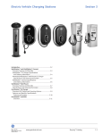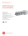
1
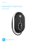
GE Energy
WattStation™ Wall Mount
User Manual
imagination at work
WattStation Wall Mount User Manual
Table of Contents
1.
Grounding Instructions ........................................................................................ 3
1.1
Safety and Compliance ...........................................................................................................................3
1.2
Grounding Instructions ............................................................................................................................3
2. Installation Instructions ...................................................................................... 3
2.1
Installation Tools and Requirements.................................................................................................3
2.2
Plug-in Version.............................................................................................................................................4
2.2.1 Before Installation ................................................................................................................................4
2.2.2 Installation................................................................................................................................................4
2.3
Hardwired Version .....................................................................................................................................5
2.3.1 Before Installation ................................................................................................................................5
2.3.2 Installation................................................................................................................................................6
3. User Manual .......................................................................................................... 9
3.1
Basic Features .............................................................................................................................................9
3.2
Turning WattStation On and Off..........................................................................................................9
3.3
Connecting and Disconnecting to Vehicle................................................................................... 10
3.4
Technical Information ........................................................................................................................... 11
3.5
Fault Indication......................................................................................................................................... 11
3.6
Fuse Replacement .................................................................................................................................. 13
4. Warranty .............................................................................................................. 13
WattStation should be installed only a licensed contractor, and/or a
licensed electrician in accordance with all applicable state, local and
national electrical codes and standards. WattStation should be
inspected by a qualified inspector prior to initial use. Under no
circumstances will compliance with the information in this manual
relieve the user of his/her responsibility to comply with all applicable
codes or safety standards.
2
GE Energy
©2011 GE Company All Right Reserved
WattStation Wall Mount User Manual
1. Grounding Instructions
1.1
Safety and Compliance
Read all instructions before using this product.
Do not use this product if the flexible power cord or charging cable are frayed, have
broken insulation, or any other signs of damage.
Do not use this product if the enclosure or the charging connector are broken, cracked,
open, or show any other indication of damage.
This document provides instructions for the wall mounted WattStation and should not be
used for any other product. Before installing WattStation you should review this manual
carefully and consult with a licensed contractor, licensed electrician, or trained
installation expert to ensure compliance with local building codes, climate conditions,
safety standards and state and local electrical codes.
1.2
Grounding Instructions
WattStation must be connected to a centrally grounded electrical system. Ground
conductors entering WattStation must be connected to the equipment grounding bar
inside the charger. Connections to WattStation shall comply with all applicable electrical
codes and ordinances.
2. Installation Instructions
2.1
Installation Tools and Requirements
Recommended Tools:
! Slotted screwdriver (3/16” or ¼”)
! Electric drill
! Wire stripper
! Wall mounting hardware (refer to section 2.2.1 or section 2.3.1)
! Phillip’s head screwdriver
! Water-tight conduit hub (hardwired version only)
3
GE Energy
©2011 GE Company All Right Reserved
WattStation Wall Mount User Manual
Torque Specification Table: (needs to be updated with info from Pradeep)
2.2
COMPONENT
TORQUE VALUE
TOLERANCE
M5 x 0.8 screw
#12 thread-cutting screw
10-32 UNF screw
6-32 UNC screw
Fuse block lugs
Field wiring lugs
Din-rail mounted terminal block lugs
Contactor lugs
Ground bar lugs
3/4" cable strain relief fitting
30 in-lb
30 in-lb
35 in-lb
12 in-lb
45 in-lb
50 in-lb
12 in-lb
50 in-lb
35 in-lb
Hand-Tight + 1/4 turn
+/- 2 in-lb
+/- 2 in-lb
+/- 5 in-lb
+/- 2 in-lb
+/- 2 in-lb
+/- 2 in-lb
+/- 2 in-lb
+/- 2 in-lb
+/- 2 in-lb
N/A
Plug-in Version
2.2.1 Before Installation
WattStation should be installed only by a licensed contractor,
and/or a licensed electrician in accordance with all applicable
state, local and national electrical codes and standards.
•
•
•
•
•
•
Ensure that a dedicated circuit, capable of supplying 30A at 208-240 VAC,
is available
Power feed must have a centrally grounded neutral in order for WattStation to
function correctly.
Wall receptacle must be a NEMA 6-50 outlet. A recommended 40A upstream
circuit breaker, located either in a panelboard or load center, should be used
Distance between the wall power receptacle and WattStation mounting should
be less than one (1) foot
Wall power receptacle with a weatherproof locking cover is recommended
Recommended mounting hardware for wood studs are 3/8" x 2" hex head lag
bolts. Recommended mounting hardware for concrete walls are 3/8" x 1-3/4"
concrete hex screws or 3/8" x 1-7/8" concrete anchors
WARNING: Danger of electrical shock or injury. Turn
OFF power at the panelboard or load center before
working inside the equipment or removing any
component. Do not remove circuit protective
devices or any other component until the power is
turned OFF.
4
GE Energy
©2011 GE Company All Right Reserved
WattStation Wall Mount User Manual
2.2.2 Installation
Step 1: Carefully unwrap the packaging and make sure the following items
are present:
- Wall Mounted WattStation unit
- Mounting wall bracket
- Template for wall-mounting holes
- Key for WattStation mounting lock (stored inside WattStation unit)
Step 2: Check for any damage to the unit, the cord or the connector. If no damage
is noticed, proceed to step 3. If damage is noticed, call 1-888-GE-RESOLve.
Step 3: Install wall mount bracket to the wall. Use the provided template to locate
wall-mounting holes to ensure hole locations match the bracket. Distance from
floor to bottom of wall mount bracket should be 18” minimum for indoor use, 24”
minimum for outdoor use, and 38” maximum for all applications per NEC 625.39.
For ADA compliant installation, refer to ADA accessibility guidelines, section 4.2
Step 4: Slide WattStation unit onto the mounting bracket, ensuring that the
opening in the back plate bracket aligns with the tab on the wall mount bracket
5
GE Energy
©2011 GE Company All Right Reserved
WattStation Wall Mount User Manual
Step 5: Lock the WattStation unit onto the mounting bracket using the
provided key
Step 6: Unwrap the plug-in cord and plug into the wall receptacle
Step 7: Lock weatherproof receptacle cover (not supplied with WattStation)
6
GE Energy
©2011 GE Company All Right Reserved
WattStation Wall Mount User Manual
2.3
Hardwired Version
2.3.1 Before Installation
WattStation should be installed only by a licensed contractor,
and/or a licensed electrician in accordance with all applicable
state, local and national electrical codes and standards.
•
•
•
•
•
•
Ensure that a dedicated circuit, capable of supplying 30A at 208-240 VAC, is
available
Power feed must have a centrally grounded neutral in order for WattStation
to function correctly.
Wall receptacle must be a NEMA 6-50 outlet. A recommended 40A upstream
circuit breaker, located either in a panelboard or load center, should be used
Power and ground wires for WattStation go in through the back of the unit as
a default. Optionally, the power may be fed through the bottom or top of the
unit. Plan ahead on how you will supply power to WattStation
Recommended mounting hardware for wood studs are 3/8" x 2" hex head lag
bolts
Recommended mounting hardware for concrete walls are 3/8" x 1-3/4"
concrete hex screws or 3/8" x 1-7/8" concrete anchors
WARNING: Danger of electrical shock or injury. Turn
OFF power at the panelboard or load center before
working inside the equipment or removing any
component. Do not remove circuit protective
devices or any other component until the power is
turned OFF.
2.3.2 Installation
Step 1: Carefully unwrap the packaging and make sure the following items
are present:
- Wall Mounted WattStation unit
- Mounting wall bracket
- Template for wall-mounting holes
- Key for WattStation mounting lock (stored inside WattStation unit)
Step 2: Check for any damage to the unit, the cord or the connector. If no damage
is noticed, proceed to step 3. If damage is noticed, call 1-888-GE-RESOLve.
7
GE Energy
©2011 GE Company All Right Reserved
WattStation Wall Mount User Manual
Step 3: Install wall mount bracket to the wall. Use the provided template to locate
wall-mounting holes to ensure hole locations match the bracket. Distance from
floor to bottom of wall mount bracket should be 18” minimum for indoor use, 24”
minimum for outdoor use, and 38” maximum for all applications per NEC 625.39.
For ADA compliant installation, refer to ADA accessibility guidelines, section 4.2.
Make sure the bracket is aligned so that power wire will fit through the WattStation
enclosure holes (for back-entry wiring only).
Step 4: Remove the oval snap-fit ring to access the cover hardware. Take off front
cover and the deadfront shield.
8
GE Energy
©2011 GE Company All Right Reserved
WattStation Wall Mount User Manual
Step 5: Remove the wire pigtail from the line side of field wiring block.
Step 6: Feed the supply power and ground wires through WattStation enclosure
holes. Slide WattStation onto the mounting bracket, ensuring that the opening in
the back plate bracket aligns with the tab on the wall mount bracket.
Step 7: Connect supply power wires to line side of fuse block and ground wire to
the ground bar.
Step 8: Replace the deadfront shield, the front cover with the provided hardware
and the oval snap-fit ring.
3. User Manual
3.1 Basic Features
!
!
!
!
!
!
!
!
!
9
Charging cord and connector provide link to electric vehicle
LED ring provides illumination around connector
Green indicator light displays when WattStation is in charge mode
Red indicator light displays when WattStation is in fault mode
On/Off button allows total power shutdown
Tamper-proof / theft-proof key lock secures WattStation to the wall bracket
Padlock option on connector provides additional physical security
Availability of plug-in or hardwired version provides installation flexibility
Entry options for supply power cable include top, bottom and rear and provide
additional flexibility for the hardwired version
GE Energy
©2011 GE Company All Right Reserved
WattStation Wall Mount User Manual
3.2 Turning WattStation On and Off
WattStation can be turned on by pressing in the On/Off pushbutton. When on, the LED
ring around the connector will glow white.
WattStation can be turned off at any time by pressing the On/Off button again. The LED
ring will turn off.
3.3 Connecting and Disconnecting to Vehicle
Connect to Vehicle
When the connector is seated in the WattStation holder, press and hold the button on the
connector handle and pull away from the holder until it is fully removed.
Press and hold the button on the connector handle and insert into the vehicle’s inlet
socket. Release the button on the connector handle when fully connected to the vehicle
inlet socket.
Once the WattStation handle is connected to the vehicle, the charge status indicator will
illuminate green.
Disconnect from Vehicle:
WattStation can be disconnected from the vehicle at any time.
Press and hold the button on top of the connector handle and pull the handle away from
the vehicle inlet socket. The charge status indicator light will turn off.
Replace the connector handle into the WattStation holder by pushing the connector
into the inlet. This will ensure the connector is locked with the metal inlet of the
WattStation holder.
10
GE Energy
©2011 GE Company All Right Reserved
WattStation Wall Mount User Manual
3.4 Technical Information
SAE Compliant
Vehicle Interface
Cable Length
AC Max Charging Power Output**
Voltage and Current Rating
AC Power Input
Recommended Service Panel
Breaker
Ground Fault Protection
Ground Monitoring
Standby Power
Outdoor Rated
Safety Compliance
Surge Protection
EMI Compliance
Operating Temperature
Operating Humidity
Unit Weight
Dimensions
Level II per J1772
SAE J1772 EV connector
16’ cable
7.2 kW (240VAC @ 30A)
208-240VAC @ 30A
208-240VAC requiring only Line 1, Line 2 and
Earth ground
2-pole 40A breaker on dedicated circuit
Internal 20mA CCID with auto-re-closure, does
not require a GFCI in service panel
Ensures ground is present between vehicle and
WattStation, and between WattStation and
load center
0 W when not charging and turned off by
pushbutton switch
NEMA 3R
ETL and CETL listed conforming to UL 2594,
2231 and 1998
6kV @ 3000A
FCC Part 15 Class A
-30°C to +50°C ambient
Up to 95% non-condensing
35 lbs
24” H x 16” W x 6” D
**WattStation determines the maximum power consumption. EV determines the actual
power consumption.
3.5 Fault Indication
When the fault indicator illuminates red, WattStation is indicating a fault.
WattStation faults will be either self-correcting or non-correcting.
•
•
11
Self-correcting: When the fault icon and LED ring around the coupler are
illuminated, the system is experiencing a self-correcting fault. In this state the
system will reset after 15 minutes, or a manual reset can be performed. Simply
remove and replace the connector to the EV, or power cycle the unit by holding
down the power button until the system turns off and pressing the power button
again to restart.
Non-correcting: When fault icon is illuminated and LED ring is not illuminated a
fault has occurred which requires a manual reset. Simply remove and replace the
connector to the EV, or power cycle the unit by holding down the power button
until the system turns off and pressing the power button again to restart.
If a fault condition persists have your local certified electrician inspect the system.
GE Energy
©2011 GE Company All Right Reserved
WattStation Wall Mount User Manual
There are six types of faults that can occur:
1.
2.
3.
4.
5.
6.
Ground Fault, Self-correcting
Contactor closed when not charging Fault, Non-correcting
Self-Test Fault, Non-correcting
Overvoltage/Undervoltage Faults, Self-correcting
Overload Fault, Non-correcting
Fan Fault, Non-correcting
Ground Fault:
WattStation can detect the presence of ground faults with a threshold of 15–20 mA
during the charging cycle. Once a ground fault is detected, WattStation will stop charging
the vehicle and the fault status indicator will turn red.
If four (4) such attempts to restart charging have occurred, WattStation will lockout the
station. The lockout will prevent any vehicle from being charged until the plug has been
disconnected from the vehicle. The fault indicator will illuminate as solid red. It is highly
recommended that service personnel examine the EV (electric vehicle)
and/or the charging cable to determine the cause of the multiple faults
before re-energizing.
If a ground fault is present immediately after WattStation begins charging, the unit will
stop charging and immediately lockout the station. The lockout will prevent any vehicle
from being charged until the plug has been disconnected from the vehicle. The fault
indicator will illuminate as solid red.
Contactor closed when not charging Fault:
WattStation internally monitors itself to ensure that it is only supplying power to the
connector when it is in a charging cycle. If WattStation is supplying power to the
connector in a non-charge cycle, WattStation will lockout. The lockout will prevent any
vehicle from being charged until power has been cycled. The fault indicator will illuminate
as solid red.
Self-Test Fault:
WattStation internally monitors its operating performance. If there is a failure of its
performance, WattStation will lockout. The fault indicator will illuminate as solid red.
Overvoltage/Undervoltage Faults:
WattStation monitors line voltage and cuts power to the EV if the voltage goes out of
range. After one (1) minute, it rechecks the voltage and will automatically re-enable
charging if the voltage returns to an acceptable range. The fault indicator will illuminate
as blinking red.
Overload Fault:
WattStation monitors the current being drawn by the EV. If this current exceeds the
capability of the unit’s fuse, charging will be interrupted and the fault status indicator will
illuminate and turn solid red. Disconnecting WattStation connector from the EV can reset
this fault.
12
GE Energy
©2011 GE Company All Right Reserved
WattStation Wall Mount User Manual
Fan Fault:
WattStation is not suitable for vehicles that require ventilation. It will provide fault
indication if a vehicle requests fan ventilation, as per SAE J1772. The fault indicator will
illuminate and turn solid red. The fault will reset if the user removes the WattStation
connector from the vehicle.
3.6 Fuse Replacement
In the event that a fuse needs to be replaced, first remove the front cover as described
in Step 4 of Section 2.3.2. The fuses will then be accessible through the dead front
shield. Remove old fuses by using a fuse puller tool. Replacement fuses should be
Cooper-Bussmann NON-40, Class K5.
4. LIMITED WARRANTY FOR GE WattStation TM (Wall)
(“this Warranty”)
WARRANTY
Any one or more of the following actions acknowledges that you have read and agree to
the terms of this warranty agreement: Your use of the GE WattStation (Wall) packaged
with this Instruction Manual (the “Hardware”), online product registration of the
Hardware, or your return of the enclosed Registration Card. GE’s warranty obligations for
this Hardware product are limited to the terms set forth in this Limited Warranty and are
limited by and subject to the Exclusions and Limitations set out below.
GE warrants that this Hardware product shall be free of defects in materials and
workmanship under normal use for a period of three (3) years from the date of
manufacture (the “Warranty Period”). If a defect in the Hardware arises and a valid claim
is received within the Warranty Period, your sole and exclusive remedy will be for GE, in
its sole discretion and to the extent permitted by law, to (1) repair the defect in the
Hardware at no charge, using new parts or refurbished parts, or (2) exchange the
Hardware with new or refurbished hardware that is functionally equivalent to the original
Hardware, (the repaired Hardware and the exchanged hardware are called the
“Remedied Hardware”). Any Remedied Hardware product will be warranted for the
remainder of the original warranty period or ninety (90) days from delivery to the
customer, whichever is longer. In order to receive the remedy set forth above, you must
contact GE during the Warranty Period at 888-437-3765 and provide the model number,
serial number and date of purchase. Upon GE’s determination that the Hardware
product should be returned to GE, return the Hardware and include with each returned
item of Hardware (i) a copy of your original purchase invoice or receipt to verify your
warranty; (ii) your name, address, and telephone number; (iii) the Return Materials
Authorization (RMA) number.
13
GE Energy
©2011 GE Company All Right Reserved
WattStation Wall Mount User Manual
In addition to the foregoing Hardware product warranty, during the Warranty Period, GE shall
also provide telephone (888-437-3765) technical support assistance.
Please note that the above warranty obligations of GE do not apply to installation service of
the Hardware.
EXCLUSIONS AND LIMITATIONS
This warranty applies only to the Hardware manufactured by or for GE that can be identified
by the “GE” trademark, trade name, or logo affixed to it. This warranty does not apply to any
non-GE hardware product or any software, even if packaged or sold with the Hardware.
Software distributed by GE with or without the GE brand name (including, but not limited to
system software) is not covered under this warranty. Refer to the End User Licensing
Agreement accompanying the software for details of your rights with respect to its use.
GE does not warrant that the operation of the Hardware will be uninterrupted or error-free.
GE is not responsible for damage arising from failure to follow instructions relating to the
Hardware’s use.
This warranty does not apply to: (a) consumable parts, such as batteries, or protective
coatings designed to diminish over time unless failure has occurred due to a defect in
materials or workmanship; (b) cosmetic damage; (c) damage caused by use with non-GE
products; (d) damage caused by accident, abuse, misuse, liquid contact, fire, earthquake or
other external causes; (e) damage caused by operating the Hardware product outside the
permitted or intended uses described by GE; (f) damage caused by service (including
upgrades and expansions) not performed by GE, a GE-authorized service provider, an
authorized representative of GE, or a qualified electrician; (g) a product or part that has been
modified to alter functionality or capability without the written permission of GE; (h) defects
caused by normal wear and tear or otherwise due to the normal aging of the product; (i)
removed or defaced GE serial numbers; or (j) damage caused by or via the network on which
the Hardware product is used including, but not limited to, any online intrusion or attack.
Important: Do not open, take apart or disassemble the Hardware in any way. Doing so may
cause damage that is not covered by this warranty. Only GE or a GE authorized service
provider should perform service on the Hardware.
TO THE EXTENT PERMITTED BY LAW, THIS WARRANTY AND THE REMEDIES SET FORTH ABOVE
ARE EXCLUSIVE AND IN LIEU OF ALL OTHER WARRANTIES, REMEDIES AND CONDITIONS,
WHETHER ORAL, WRITTEN, STATUTORY, EXPRESS OR IMPLIED. TO THE EXTENT PERMITTED BY
APPLICABLE LAW, GE SPECIFICALLY DISCLAIMS ANY AND ALL STATUTORY OR IMPLIED
WARRANTIES, INCLUDING, WITHOUT LIMITATION, WARRANTIES OF MERCHANTABILITY AND
FITNESS FOR A PARTICULAR PURPOSE AND WARRANTIES AGAINST HIDDEN OR LATENT
DEFECTS. IF GE CANNOT LAWFULLY DISCLAIM STATUTORY OR IMPLIED WARRANTIES THEN TO
14
GE Energy
©2011 GE Company All Right Reserved
WattStation Wall Mount User Manual
THE EXTENT PERMITTED BY LAW, ALL SUCH WARRANTIES SHALL BE LIMITED IN DURATION TO
THE DURATION OF THE EXPRESS WARRANTY PROVIDED IN THS WARRANTY SECTION AND TO
THE REPAIR OR REPLACEMENT SERVICE PROVIDED IN THIS WARRANTY SECTION AND
EXCLUSIONS AND LIMITATIONS PROVISION SUB-SECTION, IN EACH CASE AS DETERMINED BY
GE. No oral or written information or advice given by GE or a GE-authorized representative
shall modify or extend any warranty. If any provision is held to be illegal or unenforceable, the
legality or enforceability of the remaining provisions shall not be affected or impaired.
EXCEPT AS PROVIDED IN THIS WARRANTY AND TO THE MAXIMUM EXTENT PERMITTED BY LAW,
GE IS NOT RESPONSIBLE FOR DIRECT, SPECIAL, INCIDENTAL OR CONSEQUENTIAL DAMAGES
RESULTING FROM ANY BREACH OF WARRANTY OR CONDITION, OR UNDER ANY OTHER LEGAL
THEORY, INCLUDING BUT NOT LIMITED TO LOSS OF USE; LOSS OF REVENUE OR ACTUAL OR
ANTICIPATED PROFITS OR SAVINGS; LOSS OF, DAMAGE TO, COMPROMISE OR CORRUPTION OF
DATA; OR ANY INDIRECT OR CONSEQUENTIAL LOSS OR DAMAGE HOWSOEVER CAUSED
INCLUDING THE REPLACEMENT OF EQUIPMENT AND PROPERTY AND ANY COSTS OF
RECOVERING, PROGRAMMING OR REPRODUCING ANY PROGRAM OR DATA STORED IN OR
USED WITH THE GE PRODUCT. THE FOREGOING LIMITATION SHALL NOT APPLY TO DEATH OR
PERSONAL INJURY CLAIMS, OR ANY STATUTORY LIABILITY FOR INTENTIONAL AND GROSS
NEGLIGENT ACTS AND/OR OMISSION.
15
GE Energy
©2011 GE Company All Right Reserved
GE Energy
41 Woodford Avenue
Plainville, CT 06062
www.geindustrial.com
© 2011 GE Company
imagination at work
WattStation™ is a trademark of General Electric Company.
DEA-533 (07/11)