1
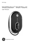
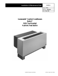
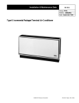
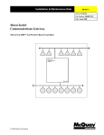
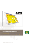
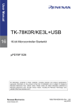
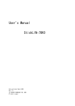
Installation & Maintenance Data
IM 657-1
Group: Controls
Part Number: 594861Y
Date: March 1998
MicroTech® Series-100
Application Specific Controller
a0196
© 1998 McQuay International
Contents
Contents ..................................................................................................................................................................2
Illustrations .............................................................................................................................................................2
Tables .......................................................................................................................................................................2
Introduction ............................................................................................................................................................4
General Description ......................................................................................................5
Component Data.....................................................................................................................................................5
Microprocessor Control Board ........................................................................................................................5
Field Wiring Terminal Board .............................................................................................................................8
Software ID..............................................................................................................................................................9
MicroTech Monitoring and Networking Options .............................................................................................9
PC Monitoring....................................................................................................................................................9
Network Master Panel.......................................................................................................................................9
Installation .................................................................................................................. 11
Panel Location and Mounting............................................................................................................................11
Field Wiring...........................................................................................................................................................12
Power.................................................................................................................................................................12
Network Communications...............................................................................................................................12
PC Connection..................................................................................................................................................14
Analog/Digital Inputs .....................................................................................................................................17
Service Information .................................................................................................... 20
Wiring Diagram.....................................................................................................................................................20
Test Procedures ....................................................................................................................................................21
LED Diagnostics ..............................................................................................................................................21
Troubleshooting Power Problems .................................................................................................................21
Troubleshooting Analog/Digital Inputs ......................................................................................................22
Troubleshooting Digital Outputs ..................................................................................................................22
MCB Replacement................................................................................................................................................22
Parts List................................................................................................................................................................23
Illustrations
Figure 1. MicroTech ASC-100 Panel Layout......................................................................................................5
Figure 2. Microprocessor Control Board (MCB)...............................................................................................6
Figure 3. Hex Switches...........................................................................................................................................6
Figure 4. Input Switches........................................................................................................................................7
Figure 5. Field Wiring Terminal Board .................................................................................................................9
Figure 6. ASC-100 Panel Dimensions................................................................................................................11
Figure 7. Field Wiring Schematic: Typical Network with ASC-100 ...............................................................14
Figure 8. RS-232 Cable Pinouts for 9-Pin Serial Ports (AMP Connector) ....................................................16
Figure 9. RS-232 Cable Pinouts for 25-Pin Serial Ports (AMP Connector) ..................................................16
Figure 10. RS-232 Cable Pinout for 9-Pin Serial Ports (Phoenix Connector)................................................16
Figure 11. RS-232 Cable Pinout for 25-Pin Serial Ports (Phoenix Connector)..............................................16
Figure 12. Analog/Digital Inputs Field Wiring Connection...........................................................................18
Figure 13. Digital Output - Normally Open Contacts ......................................................................................19
Figure 14. Digital Output - Normally Closed Contacts ...................................................................................19
Figure 15. ASC-100 Panel Schematic Legend...................................................................................................20
Figure 16, ASC-100 Panel Schematic .................................................................................................................20
Figure 17. MCB Power Connector.....................................................................................................................22
Tables
Table 1. Maximum Output Ratings.......................................................................................................................7
2
IM 657-1
Table 2. PC Specification.....................................................................................................................................10
Table 3. ASC-100 Panel Environmental Specifications...................................................................................11
McQuay, AAF, and MicroTech are registered trademarks of McQuay International.
Monitor and Open Protocol are trademarks of McQuay International.
Microsoft and MS-DOS are registered trademarks of Microsoft Corporation.
IBM is a registered trademark of International Business Machines Corporation.
©1998 McQuay International. All rights reserved throughout the world.
IM 657-1
3
Introduction
This manual provides information about the MicroTech® Series 100 Application Specific Controller
(ASC-100). It describes the ASC-100’s components, field wiring requirements, and service procedures.
The versatile ASC-100 controller monitors and controls a variety of mechanical and electrical
environmental equipment in a MicroTech building automation system (BAS). The ASC-100 uses
custom configured software written for each application. This provides the customers with a wide
range of options for monitoring and controlling their HVAC equipment.
!
WARNING
Electric shock hazard. Can cause personal injury or equipment damage.
This equipment must be properly grounded. Connections and service to the MicroTech
control panel must be performed only by personnel that are knowledgeable in the operation
of the equipment being controlled.
!
CAUTION
Static sensitive components. A static discharge while handling electronic circuit boards
can cause damage to the components.
Discharge any static electrical charge by touching the bare metal inside the control panel
before performing any service work. Never unplug any cables, circuit board terminal blocks,
or power plugs while power is applied to the panel.
NOTICE
This equipment generates, uses and can radiate radio frequency energy and, if not
installed and used in accordance with this instruction manual, may cause interference to
radio communications. It has been tested and found to comply with the limits for a Class A
digital device, pursuant to part 15 of the FCC rules. These limits are designed to provide
reasonable protection against harmful interference when the equipment is operated in a
commercial environment. Operation of this equipment in a residential area is likely to
cause harmful interference in which case users will be required to correct the interference
at their own expense. McQuay International disclaims any liability resulting from any
interference or for the correction thereof.
4
IM 657-1
General Description
The MicroTech Series 100 Application Specific Controller (ASC-100) is a microprocessor-based
controller used to monitor and control pieces of hardware that do not have MicroTech controls
factory installed. Typical applications of the ASC-100 include control of lighting, boiler systems,
circulating pumps, and air handlers.
The ASC-100’s design offers input and output flexibility. The ASC-100 supports eight inputs (analog
or digital) and eight digital outputs.
Component Data
Figure 1 shows the control panel layout for the ASC-100. The main components of the control system
include the Microprocessor Control Board (MCB) and the Field Wiring Terminal Board (FWTB). The
MCB contains hex switches, power-in connector, relays, status LEDs, inputs switches, communication
ports, and a 1.5-amp fuse.
The FWTB contains terminal blocks with screw terminals for connecting analog/digital inputs, digital
outputs, and auxiliary power.
Transformers T1 and T2 provide power to the controller. A 0.5-amp circuit breaker protects the
controller against power surges and over-voltages. These major components are mounted inside a
NEMA 1 enclosure.
Figure 1. MicroTech ASC-100 Panel Layout
L1
L2
T2
51
52
53
54
55
GRD
T1
TB1
CB1
MCB
FWTB
Microprocessor Control Board
Figure 2 shows the Microprocessor Control Board (MCB). It contains a microprocessor that has
custom software written to monitor and control the equipment connected to the ASC-100. This
custom software is normally loaded into the MCB at the job-site. The various MCB connections and
components are described below.
IM 657-1
5
Figure 2. Microprocessor Control Board (MCB)
Electromechanical
Relays
Reset LED
Hex Switches
Output Status
LEDs
HI
LO
Port A Select
Port A
Status LED
Port B
1 2 3
Watchdog LED
1 2 3
Communications
Ports
L1
Digital Input
Status LEDs
Input Switches
a0191
Hex Switches
The MCB includes two hex (hexadecimal) switches that are used to set the ASC-100 controller’s
network address.
The HI and LO hex switches are shown in Figure 3 (hex switch setting 01 shown). A “hex switch
setting” is defined as the HI switch digit followed by the LO switch digit. For example, a hex switch
setting of 2F would have the HI switch set to “2” and the LO switch set to “F.” In most cases, the
ASC-100’s hex switch setting is set between 01 and 40 (level-2).
Note: To change the setting of a hex switch, use a 3/32 -inch tip, slotted-blade screwdriver. Insert the
screwdriver into the slot on the hex switch, then turn it to the position required. If a hex switch setting
is changed, cycle power to the MCB by opening and closing the circuit breaker located in the power
section of the control panel. By cycling power, the new switch setting is entered into memory.
Figure 3. Hex Switches
6
IM 657-1
Power In Connector
The MCB receives 18 Vac, center-tapped power from transformer T2 through the Power In connector.
This power drives all logic and communications circuitry. Refer to the panel’s wiring diagram or Figure
16 for more information.
Electromechanical Relays
The single-pole double through (SPDT) electromechanical relays drive digital outputs connected to
the Field Wiring Terminal Board. Depending on the wiring setup, the relay can be normally open or
normally closed (see “Digital Outputs” below). See Table 1 for the relay’s output ratings.
Table 1. Maximum Output Ratings
Voltage
Output Rating
30 Vdc
20 watts resistive,
10 watts inductive
30 Vac
30 VA resistive,
20 VA inductive
LEDs
The MCB has the following LEDs: Digital Output Status, Digital Input Status, Watchdog, Reset, and
Status.
•
The Digital Output Status LED is lit when a digital output is activated. There are eight Digital
Output Status LEDs, one for each electromechanical relay. When the relay is energized, the LED
illuminates.
•
The Digital Input Status LED is lit when an input switch is set to “Contact” and a digital input
signal is present. There are eight Digital Input Status LEDs located below the input switches (see
“Input Switches” below).
•
The Reset LED illuminates for 5 seconds when power is applied to the MCB. The LED’s location
is on the right side of the MCB mounting plate.
•
The Status LED indicates when the MCB is operational and ready to communicate by flashing.
•
The Watchdog LED operates the same as the Reset LED.
Input Switches
The input switches select the type of input signal connected to the Field Wiring Terminal Board (see
Figure 4). There are eight input switches with each switch having four positions (thermistor, 4-20 mA,
0–5 Vdc, or contact). For example, if the device connected to input 0 is a thermistor type input, input
switch SW0 is set to position 1. Switches SW1 through SW7 are set the same way depending on the
type of input that is field wired to the Field Wiring Terminal Board.
Figure 4. Input Switches
INPUT SWITCHES
SW0 SW1 SW2 SW3 SW4 SW5 SW6 SW7
IM 657-1
THERMISTOR
(POS. 1)
4–20 mA
(POS. 2)
0–5 Vdc
(POS. 3)
CONTACT
(POS. 4)
7
Communication Ports
The MCB contains two communication ports: port A and port B. Each port includes three terminals.
The Port A Select switch, located below the hex switches, enables the user to select RS-232 or RS-485
data transmission for port A. Moving the switch to the left position sets up RS-232 data transmission
while moving the switch to the right sets up RS-485 data transmission. The MCB uses Phoenix type
connectors for the ports. Following are brief descriptions of each port’s function.
Port A
Port A (TS1) is usually used for communications with an IBM compatible PC using the RS232 interface standard. The PC can be directly connected, over a limited distance, with a
twisted, shielded pair cable. The default communications rate is 9600 bps. For more
information, see “PC Connection” in the “Field Wiring” section of this manual.
Port B
Port B is for MicroTech network communications using the RS-485 interface standard. A
twisted, shielded pair cable should be connected to port B (TS2). The communications rate
is 9600 bps. For more information, see “Network Communications” in the “Field Wiring”
section of this manual.
Field Wiring Terminal Board
Figure 5 shows the Field Wiring Terminal Board. The Field Wiring Terminal Board has field wiring
terminals for analog/digital inputs, digital outputs, and auxiliary power.
Analog/Digital Inputs
Screw terminals on TB4 and TB5 enable the user to connect an analog input or a digital input (dry
contact ) to the ASC-100. Inputs are labeled IN 0 through IN 7. Each input has two screw terminals
associated with it. For example: IN 0 includes screw terminals TB5-28 and TB5-29 (see Figure 5). For
more information, see “Analog/Digital Inputs” in the “Field Wiring” section of this manual.
Digital Outputs
Screw terminals on TB1, TB2, and TB3 enable the user to wire a digital output to the ASC-100. The
digital outputs are labeled Output 0 through Output 7. Each output consists of three screw terminals.
For example: Output 0 includes screw terminals TB1-1, TB1-2, and TB1-3. If the output is to be
normally open, screw terminals 1 and 2 are used. If the output is to be normally closed, screw terminals
2 and 3 are used. For more information, see “Digital Outputs” in the “Field Wiring” section of this
manual.
Power
Auxiliary power sources are available at screw terminals TB3-25 and TB3-26 (13 Vdc), and screw
terminals TB4-36 and TB5-37 (5 Vdc). These terminals can be used to power peripheral devices.
8
IM 657-1
Figure 5. Field Wiring Terminal Board
NMP
TB1
Hot
Hardware
by others
MCB
L1
115 Volts AC
Power Supply
(Fused 15 Amps)
Port A
Port B
Optional Monitor software package
Optional PC Communications Cable Kit
L2
Neutral
GND
Legend
TB3
B+
Factory wiring
Field wiring terminal
B–
Field wiring
Twisted, shielded pair
cable with drain wire
BLK
WHT
GND
Screw Chiller #1
TB4
53
54
BLK
W H T
55
Screw Chiller #2
ASC
MCB
TS1
TB4
A–
53
Port A
A+
GND
54
TS2
B–
B+
Port B
GND
WHT
Applied Rooftop Unit
TB2
BLK
BLK
WHT
55
Phoenix
Connector
128
129
130
a0194
Software ID
MicroTech software for the ASC-100 is custom configured for each application. The software is field
installed in each panel. The software is identified by a program code (also referred to as the “Ident”).
The program code is encoded in the controller’s memory and is available for display by using a PC
equipped with Monitor™ software.
MicroTech Monitoring and Networking Options
PC Monitoring
A PC (personal computer) equipped with the appropriate Monitor software can be used to provide a
high-level interface with a MicroTech network (see PC specification below). Monitor software features
a Windows™-based display, multilevel password access, and advanced trend-logging. The PC can be
connected to the ASC-100 controller either directly, via a single twisted, shielded pair cable, or
remotely, via phone lines with an optional modem. For more information on connecting the PC to the
controller, refer to “PC Connection” in the “Field Wiring” section of this manual.
For the most convenience and best operation, the PC should be considered dedicated to the
MicroTech system. However, you can exit the Monitor program to perform other tasks without
affecting equipment control. Refer to the Monitor software user’s manual the for more information.
PC Specification
A directly or remotely connected computer can be used for monitoring ASC-100 and unit operation,
changing setpoints, scheduling, trend logging, downloading software, and diagnostics. The PC must
be an IBM or 100% true compatible. Table 2 shows the preferred and minimum PC specifications.
Network Master Panel
The MicroTech Network Master Panel (NMP) allows the ASC-100 and its associated units to be
incorporated into a building-wide network with other MicroTech unit and auxiliary controllers. In
IM 657-1
9
conjunction with a PC and Monitor software, it gives the building operator the capability to perform
advanced equipment control and monitoring from a central or remote location.
The following features are provided by the optional NMP:
•
Remote unit monitoring
•
Advanced scheduling features
•
Advanced alarm management
•
Global operator override by unit type
•
Demand metering
•
Historical electrical data logging
For further information, contact your McQuay sales representative.
Table 2. PC Specification
Preferred Configuration
Minimum Configuration
Pentium processor or better
386SX processor, 16 MHz
16 MB of RAM or better
4 MB of RAM
340 MB hard disk drive or better
60 MB hard disk drive
3½” floppy disk drive
3½” floppy disk drive
Serial port (9 pin male)
Serial port (9 or 25 pin male)
Parallel port
–
Internal time clock, battery backed
Internal time clock, battery backed
Super VGA graphics capability
VGA graphics capability
Super VGA monitor
VGA monitor
Printer
–
Bus mouse or trackball
Serial mouse or trackball*
101 enhanced keyboard
101 enhanced keyboard
9600 baud modem, compatible with the AT command
set (optional)
1200 baud modem, compatible with the AT command
set (optional)
–
MS-DOS® 5.0
®
®
Microsoft Windows 95/98
Microsoft ® Windows ® 3.1
MicroTech ® Monitor™ for Windows software
MicroTech ® Monitor™ for Windows software
* If a serial pointing device is used, there must be another serial port available for connecting the PC to the MicroTech controller.
10
IM 657-1
Installation
Panel Location and Mounting
The ASC-100 panel is suitable for indoor use only. Table 3 lists the allowable temperature and
humidity ranges. Locate the panel at a convenient height, and allow adequate clearance for the door
swing. Mount the panel to the wall with screws or bolts. Four ¼-inch openings are provided at the
corners of the panel. The panel weighs approximately 50 lb. (22.5 kg). Figure 6 shows the panel
dimensions.
The ASC-100 panel is equipped with special door hinges that have a friction adjustment screw. By
adjusting this screw, you can prevent the panel door from swinging open or closed unexpectedly.
Table 3. ASC-100 Panel Environmental Specifications
Panel State
Temperature
Relative Humidity
Operating
30 – 100°F
10 – 90% (noncondensing)
In storage
0 – 125°F
10 – 90% (noncondensing)
Figure 6. ASC-100 Panel Dimensions
7/8" (22) Dia. knockouts
(4 on left and right sides)
1/4" (6.4) Dia.
mounting slots (2)
18-1/4"
(464)
17-3/8"
(441.3)
12-3/4"
(324)
20"
(508)
7-1/4"
(184)
1-3/4"
(44.5)
1/4" (6.4) Dia. (2)
2"
(50.8)
16"
(406.4)
18"
(457)
1"
(25.4)
4-1/8"
(104.75)
1-5/8"
(41.3)
Front View
Left Side View
2"
(51)
7/8" (22) Dia. knockouts
(4 on top and bottom)
1-7/8"
(47.6)
6-5/8"
(182.3)
11-3/8"
(288.9)
16-1/8"
(409.6)
a0193
Bottom View
IM 657-1
11
Field Wiring
Following are descriptions of the various field wiring requirements and options. A typical field wiring
diagram is shown in Figure 7. Wiring must comply with the National Electrical Code and all local codes
and ordinances. The warranty is void if wiring is not in accordance with these instructions.
The panel is divided into high and low voltage sections by a sheet metal barrier. The power wiring
should enter the high voltage section. The communications wiring should enter the low voltage
section. Wiring penetrations must be made only through the 7/8 -inch knockouts provided.
Note: High voltage wires should not pass through the low voltage section and the low voltage wires
should not pass through the high voltage section
Power
!
WARNING
Electric shock hazard. Can cause personal injury or death.
This equipment must be properly grounded.
All protective deadfront panels must be reinstalled and secured when power wiring is
complete.
The ASC-100 panel requires a 115 Vac power supply. The supply connects to terminals L1 and L2 in
the high voltage section. The panel must be properly grounded by connecting the ground lug (GRD)
to earth ground. Refer to Figure 7. Power wiring must be sized to carry at least 5 amps.
To gain access to the high voltage section, remove the deadfront barrier. It is attached to the panel
with two 5/1 6 -inch hex screws. Replace this deadfront when the wiring is complete.
A 0.5-amp circuit breaker (CB1), located at the right side of the panel in the high voltage section,
internally protects the panel. The push-button circuit breaker also acts an on-off switch for the panel.
Pushing the button in energizes the panel. Pushing the button again de-energizes the panel.
Note: A white ring on the switch shaft indicates when the panel is de-energized.
Network Communications
For network communications to occur, a twisted, shielded pair cable must be connected between an
NMP or other MicroTech control panel, and the ASC-100. This interconnecting, “daisy-chain” wiring
is shown in Figure 7. Network communications is accomplished using the RS-485 interface standard at
9600 baud.
About MicroTech Network Architecture
All controllers in a MicroTech network are assigned a “level”: level 1, level 2, or level 3. All networks
must have one level-1 controller to coordinate communications. Multiple level-2 controllers connect to
the level-1 controller with a communications “trunk,” an isolated section of the daisy-chained network
wiring. In Figure 7, the network wiring between all controllers is a trunk. Multiple level-3 controllers
can be connected to a level-2 controller with a separate trunk. The maximum allowable length of a
communications trunk is 5000 feet.
For a typical network which includes an ASC-100, a Network Master Panel (NMP) is the level-1
controller and the ASC-100 and other unit controllers are level-2 controllers.
Cable Specification
The network communications cable must meet the following minimum requirements: twisted, shielded
pair with drain wire, 300 V, 60°C, 20 AWG, polyethylene insulated, with a PVC outer jacket (Belden
8762 or equivalent).
12
IM 657-1
Some local codes or applications may require the use of plenum rated cable. Do not install the cable
in the same conduit with power wiring.
Note: Ideally, one continuous piece of cable should connect any two controllers. This reduces the
risk of communications errors. If the cable must be spliced, use crimp-type butt connectors (good) or
solder (best). Do not use wire nuts.
Wiring Instructions
The network connection to the ASC-100 panel and other level-2 controllers is at port B on their MCBs
(Microprocessor Control Board).
As shown in Figure 7, field wiring to port B on these controllers can be accomplished by connecting
the network cable to terminals B+, B-, and GND in the level-1 NMP, to the B+, B-, and GND terminals in
each of the level-2 unit controllers, and finally, to the Phoenix connector, which plugs into the ASC100’s port B. Refer to the product-specific installation and maintenance manuals to find the correct
wiring detail.
Note: The unit controller designations shown in Figure 7 (“Screw Chiller #1,” “Screw Chiller #2,”
“Applied Rooftop”), are established by the network address, not the physical position of the
controller in the daisy chain. The networked controllers can be wired in any order. For example, the
NMP Panel could be connected between Screw Chiller #1 and Screw Chiller #2. It is highly
recommended that the installing contractor keep track of the physical order of the controllers on
the daisy-chained trunk by preparing a schedule. This facilitates troubleshooting any network
communications problems that may occur.
Use the following procedure to perform the network wiring:
1.
Before beginning, verify that the port B plug is disconnected from every controller on the
communications trunk being wired. These plugs are connected during the commissioning
procedure. This is a precaution to prevent stray high voltage from damaging the controllers. Any
voltage greater than 12 V can damage the board’s communications drivers.
2.
Connect the network cable in a daisy-chain manner as shown in Figure 7. Use caution to ensure
that the correct polarity is maintained at each controller. Be sure to connect each cable's shield to
the controllers as shown in the figure. The positive (+), negative (–), and shield (ground)
conductor must be continuous over the trunk.
Note: Refer to the product-specific installation and maintenance manuals to find the correct
wiring detail and field wiring connections.
IM 657-1
13
Figure 7. Field Wiring Schematic: Typical Network with ASC-100
NMP
TB1
Hardware
by others
MCB
L1
Hot
115 Volts AC
Power Supply
(Fused 15 Amps)
Port A Port B
Optional Monitor software package
Optional PC Communications Cable Kit
L2
Neutral
GND
Legend
TB3
B+
Factory wiring
Field wiring terminal
B–
Field wiring
Twisted, shielded pair
cable with drain wire
BLK
WHT
GND
Screw Chiller #1
TB4
53
54
BLK
WHT
55
Screw Chiller #2
ASC
TS1
TB4
MCB
A–
53
Port A
A+
GND
54
TS2
B–
B+
55
Port B
TB2
BLK
Applied Rooftop Unit
WHT
BLK
WHT
GND
Phoenix
Connector
128
129
130
a0194
PC Connection
Regardless of whether the PC is connected directly or remotely via phone lines, the connection to any
MicroTech controller is at port A on the MCB. It is best to connect a PC to a level-1 controller
because faster data transmission results; however, a PC can be connected to any level-2 controller
that does not have level-3 controllers associated with it. Either way, the PC has access to the entire
network (see note below). In the typical application, the NMP is a level 1, and the ASC-100 is a level 2.
See “Network Communications” above for more on network architecture.
14
IM 657-1
It is possible to connect two or more PCs to the network, but only one PC can be connected to any
one controller. The PC that is used most often should be connected to the level-1 controller for better
performance. For example, you may have one PC at the building that you use during the week and
another PC at home that you occasionally use on weekends. In this situation, you may want to
connect the on-site PC to the level-1 controller and the modem for the off-site PC to a level-2
controller.
Note: If a PC is connected to a level-2 controller, a level-1 controller must be set up to poll that level-2
controller so that the PC has access to the entire network. For information on how to set up the level-1
controller to poll the level-2 controller, see the operation manual for the particular controller being
used.
Direct Connection
An RS-232 communications cable kit allows a PC to directly connect to any MicroTech controller. It is
available from McQuay International. The cable has a female DB9 connector for connection to the
PC’s 9-pin serial port. (If the PC has a 25-pin serial port, obtain an adapter.) The cable length is 12 feet.
If more length is required, a twisted, shielded pair cable can be spliced into the kit cable (see “Cable
Specification” below). If this is done, splice the conductors with crimp-type butt connectors (good) or
solder (best). Do not use wire nuts. The maximum allowable cable length for direct connection
between the PC and a controller is 50 feet. If additional length is needed, an RS-232 Cable Extension
Kit is available from McQuay International (see Bulletin No. IM 482, RS-232 Distance Extension).
Remote Connection
A voice quality, direct-dial telephone line is required for remote or off-site PC access to the network.
The phone line should be terminated with a standard RJ-11 modular phone plug. A modem enables a
remote or off-site PC to communicate with the networked controllers via phone lines.
A modem that can be field installed in a MicroTech controller is available from McQuay International.
The kit comes complete with a 14,400 bps modem (set up for 9600 bps) and an interface cable. If a
remote PC connection is required, it is recommended that the modem at the MicroTech controller be
supplied by McQuay International.
Installation and wiring instructions for the MicroTech Modem Kit are included in Bulletin No. IM 682,
MicroTech Modem Kit. This bulletin is included with the kit.
Cable Specification for Direct PC Connection
A properly terminated, twisted, shielded pair cable is required to directly connect a PC to a MicroTech
controller. The cable must meet the following minimum requirements: twisted, shielded pair with drain
wire, 300 V, 60°C, 20 AWG, polyethylene insulated, with a PVC outer jacket (Belden 8762 or
equivalent). It must also be properly terminated to an AMP or Phoenix plug on one end and a female
DB9 or DB25 connector on the other. See Figures 8 and 9 for AMP cable pinouts and Figures 10 and
11 for Phoenix cable pinouts.
The DB9 or DB25 connector is for connection to a 9-pin or 25-pin serial port on the PC. Note that
some local codes or applications may require the use of plenum rated cable. Do not install the cable
in the same conduit with power wiring.
Note: The cable included with the PC Communications Cable Kit is terminated with an AMP plug. To
use an AMP plug on an ASC-100, an adapter cable is needed due to the Phoenix type plug used. This
adapter cable is included in the PC Communications Cable Kit.
IM 657-1
15
Figure 8. RS-232 Cable Pinouts for 9-Pin Serial Ports (AMP Connector)
AMP Plug
Signal
TD
–
Pin
1
RD
GND
–
3
5
6
2
Female DB-9
White
Black
Shield
Pin
1
Signal
DCD
2
RD
3
4
5
TD
DTR
GND
6
DSR
7
8
RTS
CTS
a0109
Figure 9. RS-232 Cable Pinouts for 25-Pin Serial Ports (AMP Connector)
AMP Plug
Signal Pin
TD
–
1
2
RD
GND
–
3
5
6
Black
White
Shield
Female DB-25
Pin
Signal
2
3
TD
RD
4
5
RTS
CTS
6
7
DSR
GND
8
20
DCD
DTR
a0110
Figure 10. RS-232 Cable Pinout for 9-Pin Serial Ports (Phoenix Connector)
Phoenix Plug
Signal
Pin
GND
1
TD
RD
2
3
Female DB-9
Pin
Signal
1
DCD
Black
2
3
RD
TD
Shield
4
5
6
DTR
GND
DSR
7
8
RTS
CTS
White
Figure 11. RS-232 Cable Pinout for 25-Pin Serial Ports (Phoenix Connector)
Phoenix Plug
Signal
Pin
Female DB-25
Pin
Signal
GND
1
Black
2
TD
TD
RD
2
3
White
3
4
RD
RTS
5
6
7
CTS
DSR
GND
8
20
DCD
DTR
Shield
16
IM 657-1
Analog/Digital Inputs
When connecting any analog or digital input device to the ASC-100, the field wiring connection is
made at the Field Wiring Terminal Board (see Figure 12 below). A maximum of eight analog inputs,
eight digital inputs, or a combination of eight analog and digital inputs can be wired to the ASC-100.
On the Field Wiring Terminal Board, terminal blocks TB4 and TB5 contain screw terminals for the
wiring of analog or digital inputs.
!
CAUTION
Ground loop current hazard. Can cause equipment damage.
External 4–20 mA signals must be isolated from any ground other than the MicroTech
controller chassis ground. If it is not, ground loop currents could occur which could damage
the MicroTech controller. If the device or system providing the external signal is connected
to a ground other that the MicroTech controller chassis, be sure that it is providing an
isolated output, or condition the output with a signal isolator.
Analog/Digital Inputs Cable Specifications
The cable for analog or digital inputs must meet the following minimum requirements:
•
Twisted, shielded with drain wire (except digital inputs)
•
300 V, 60° C
•
20 AWG
•
Polyethylene insulated with PVC outer jacket.
Depending on the application, either two conductors (Belden 8762 or equivalent) or three conductors
(Belden 8772 or equivalent) are required. Note that some local codes or applications may require the
use of plenum rated cable. Do not install the cable in the same conduit with power wiring.
Analog/Digital Inputs – Input Switch Selection
When wiring to the analog or digital input device is complete, select the type of input using the Input
Switches (see Figure 4) located on the MCB. In Figure 12, IN 0 is connected to an analog input such
as a sensor; therefore, Input Switch SW0 is set to Thermistor. IN 3 is connected to a digital input;
therefore, Input Switch SW3 is set to Contact.
IM 657-1
17
Figure 12. Analog/Digital Inputs Field Wiring Connection
MCB
Field Wiring
Terminal Board
Input Switches
SW0
SW1 SW 2 SW3
SW4
SW5 SW6
SW7
Thermistor
4-20 mA
IN 0
0-5 Vdc
IN 1
IN 2
IN 3
IN 4
IN 5
IN 6
IN 7
Contact
TB5
Analog Input
TB4
Digital Input
Digital Outputs
When connecting any digital output to the ASC-100, the field wiring connection is made at the Field
Wiring Terminal Board (see “Wiring Instructions” below). A maximum of eight digital outputs can be
wired to the ASC-100. On the Field Wiring Terminal Board, terminal blocks TB1, TB2, and TB3 contain
screw terminals for wiring digital outputs.
The digital outputs can be wired for normally open contacts (see Figure 13) or normally closed
contacts (see Figure 14).
18
IM 657-1
Figure 13. Digital Output - Normally Open Contacts
Relay for
Digital Output
TB1
1
2
3
4
5
6
7
8
TB2
9
Normally Open
MCB
Field Wiring
Terminal Board
Digital
Output
Figure 14. Digital Output - Normally Closed Contacts
Relay for
Digital Output
TB1
1
2
3
4
5
6
7
8
TB2
9
Normally Closed
MCB
Field Wiring
Terminal Board
Digital
Output
IM 657-1
19
Service Information
B
Wiring Diagram
The following wiring diagram is identical to the one in the ASC-100 Panel. It is reproduced here for
your convenience. The legend is shown in Figure 15.
Figure 15. ASC-100 Panel Schematic Legend
Component Designation
Description
CB1
Circuit Breaker
MCB
Microprocessor Control Board
T1
Transformer: 115/24 Vac
T2
Transformer: 24 Vac/18 Vac-CT
Factory Wire Number
Field Wiring Terminal
Field Wiring
Printed Circuit Board Terminal
Twisted, Shielded Pair Cable
Figure 16, ASC-100 Panel Schematic
HOT
NEUTRAL
1 1 5 V O L T S AC. .
POWERSUPPLY
(FU S E D 1 5 A M P S )
CB1
L1
900
1
(0.5AMP)
50
901
2
115V
BK
902
51
L2
W
GRD
GRD
903
T1
933
910
Y
BL
24V
904
54
909
906
YR
/
931
55
Y
9V
BL
24V
9V
907
Y
908
52
T2
BL
905
929
53
M J
930
932
4
24VAC
3
GND
2
9VAC
1
9VAC
TB1
1
2
3
4
O U T P U T0
5
TB2
6
7
O U T P U T1
8
9
10
O U T P U T2
11
12
13
O U T P U T3
14
15
16
O U T P U T4
17
18
O U T P U T5
19
H2
O U T P U T6
TS1
FIELD
3
2
O U T P U T7
23
13VDC
25
13VDC
26
24
P
E
3
2
1
22
BOARD
TS2
FROMNETWORK
MASTERPANEL
PORTB.
21
T E R M INA L
G R D
20
T
1
P
TOPERSONAL
COMPUTER
G R D
A S C
PERSONALITY
BOARD
G R O U N D 27
IN0
28
IN1
29
30
IN2
31
32
IN3
33
TB5
34
35
IN4
5VDC
36
37 38
IN5
39
IN6
40
41
IN7
42
43
44
5VDC
45
TB4
O
O
a0195
20
IM 657-1
Test Procedures
A listing of MicroTech related part numbers is included in the “Parts List” section of this manual. If
the MCB must be replaced, refer to the “MCB Replacement” section of this manual.
LED Diagnostics
The MCB LED indications can aid in controller diagnostics. If the status LEDs do not operate
normally as described in the “Component Data” section of this manual, there is a problem with the
MCB. Following are troubleshooting procedures for the various symptoms.
Reset and Watchdog LEDs Remain On
If the Reset and Watchdog LEDs remain on after the 5-second self-test period, it is likely that the MCB
is defective. This also can occur in some instances if there is a power supply problem. Refer to
“Troubleshooting Power Problems” below.
Red and Green LEDs Off
If all the LEDs do not turn on after power is applied to the controller, there is likely a defective
component or a problem in the controller's power distribution circuits. Refer to “Troubleshooting
Power Problems” below.
Troubleshooting Power Problems
The MCB receives 18 Vac, center-tapped power through transformer T2. Power problems can be
caused by a defective component, which can either blow a fuse or create an excessive load on the
power supply. An excessive load can lower the power supply voltages to unacceptable levels. Use the
following procedure to isolate the problem. Note that this procedure may require a spare MCB fuse
(see parts list). Refer to the panel wiring diagram.
1.
Verify that circuit breaker CB1 is closed.
2.
Remove the MCB Power connector (see Figure 17).
3.
Check for 9 Vac between terminals 2 and 3 on the plug. (Readings of 9–12 Vac are acceptable.)
a.
b.
IM 657-1
If 9 Vac is present between the terminals, go to step 4.
If 9 Vac is not present between the terminals, go to step 5.
4.
Check for 9 Vac between terminals 1 and 3 on the plug.
a. If 9 Vac is present between the terminals, go to step 6.
b. If 9 Vac is not present between the terminals, go to step 5.
5.
Check transformers T2 and T1 and all wiring between the 115 Vac source and the MCB Power
connector.
6.
Remove power from the controller by opening circuit breaker CB1.
7.
Check the MCB power supply input fuse (F1) with an ohmmeter. A good fuse has negligible
resistance across it (less than 2 ohms).
a. If the fuse is blown, replace it. Go to step 8.
b. If the fuse is intact, the MCB is defective.
8.
Reconnect the MCB Power connector, cycle power to the controller (close and then open CB1),
and then check the power fuse again.
a. If the fuse is blown, the MCB is defective.
21
Figure 17. MCB Power Connector
4
3
GND
2
9 VAC
1
9 VAC
Troubleshooting Analog/Digital Inputs
If the MCB appears to be functioning properly and the analog input or digital input is not being read
by the MCB, perform the following procedure:
1.
Try cycling power to the controller by opening and then closing circuit breaker CB1.
2.
Check the Input Switches to see if they correspond to the type of input connected to the Field
Wiring Terminal Board. Power must be off when changing a position of an Input Switch.
3.
Check the edge card connection between the MCB and the Field Wiring Terminal Board and the
field wiring connections from the analog or digital input device. Look for bent pins or miswires.
Restore power after reconnecting the Field Wiring Terminal Board and any disconnected wires.
4.
If the problem persists, try swapping a known good Field Wiring Terminal Board, analog input
device, or digital input. Swap these components separately to isolate the problem. Remove power
from the controller before disconnecting the suspect component, and restore power after
connecting the replacement component. If the problem persists, it is likely that the MCB is
defective.
Troubleshooting Digital Outputs
If the MCB appears to be functioning properly and the digital output is not functioning properly,
perform the following procedure:
1.
Try cycling power to the controller by opening then closing circuit breaker CB1.
2.
Check the edge card connection between the MCB and the Field Wiring Terminal Board, and the
field wiring connection from the digital output device. Look for bent pins or miswires. Restore
power after reconnecting the Field Wiring Terminal Board and any disconnected wires.
3.
Swap a known good electromechanical relay in place of the relay whose output is not functioning
properly.
4.
If the problem persists, try swapping a known good Field Wiring Terminal Board or digital output
device. Swap these components separately to isolate the problem. Remove power from the
controller before disconnecting the suspect component, and restore power after connecting the
replacement component. If the problem persists, it is likely that the MCB is defective.
MCB Replacement
If an MCB board is defective and must be replaced, the proper controller software must be loaded into
the replacement MCB. This can be done at the building site–if a PC equipped with appropriate
Monitor software is available or the MicroTech panel is equipped with a modem.
Job-specific Monitor software includes each unit and auxiliary controller’s program. Therefore, it is
possible to download the proper controller software to a replacement MCB at the building site if a PC
equipped with that job’s Monitor software is available.
22
IM 657-1
In addition, if the controller’s configuration data was stored on the PC hard drive prior to the MCB
failure, the exact configuration data can be restored. Refer to the user’s manual supplied with the
Monitor software for more information.
A MicroTech panel equipped with a modem allows the downloading of the proper controller software
via a phone line. McQuayService or MicroTech engineering can connect to the modem and download
the proper controller software to the new MCB.
Parts List
Component
Designation
Description
Part No.
MCB
¬ Microprocessor Control Board
658144B-01
–
Field Wiring Terminal Board
658102B-01
T1
Transformer: 115/24 Vac
606308B-01
T2
Transformer: 24/18 Vac, Center Tapped
467381B-14
CB1
Circuit Breaker
7350733-03
F1
Fuse: MCB Input Power, 1.5 Amp (Bussman No. GDC-1.5A)
658296A-01
–
PC Communications Cable Kit
0057186802
–
MicroTech Modem Kit
0072140601
Notes:
1. If desired, the factory can download the correct software into the replacement MCB prior to shipment. See the “MCB
Replacement” section above for more information.
IM 657-1
23
13600 Industrial Park Boulevard, P.O. Box 1551, Minneapolis, MN 55440 USA (612) 553-5330