Download Avid Adrenaline User Manual
Transcript
Using the Avid Adrenaline Important Information Avid recommends that you read all the information in these installation instructions before connecting or using your new hardware and software. The following topics explain how to use and connect cables and devices to the Avid Adrenaline Digital Nonlinear Accelerator (DNA) and how to connect specific devices to an Avid-supported PC or Macintosh system that the Avid Adrenaline is connected to. The PC and Macintosh systems supported for your Avid Adrenaline can change at any time. n Please look at the ReadMe file that installs with the application. It contains important information that you should use in conjunction with the information presented in these topics. See the following topics: • Overview • Avid Adrenaline Front and Rear Panel • Synchronizing Audio and Video Equipment • Power-On Self-Tests • 1394 Requirements • Connecting Peripheral Equipment • System Connections and Configurations • Connecting Serial and MIDI Port Devices • Storage • Specifications Using the Avid Adrenaline Overview The Avid Adrenaline is designed to capture and output analog media and digital media (DV 25) using digital decks, cameras, and digital audiotapes. The Avid Adrenaline is powered by an autosensing power supply connected by a standard power cord to a wall plug or power strip. The Avid Adrenaline accepts video and audio in different formats and resolutions, and changes these formats and resolutions to Avid-specific data for transfer to the Avid editing system over a 1394 (FireWire) cable. The data transfer uses an Avid-specific protocol that describes the format and resolution of the data being input. You then edit the data on the Avid editing system and return it to the Avid Adrenaline to be changed back to the proper format and resolution as needed for video and audio output. The Avid Adrenaline consists of: • The Avid Adrenaline enclosure, backplane, power supply, and power cord • A standard-definition (SD) video I/O board • A high-definition (HD) video I/O board, called the Avid DNxcel • A four-channel audio I/O board A Professional/Consumer In audio cable is provided with the Avid Adrenaline that allows you to input four channels of analog audio. The cable has a DB25 connector at one end that plugs into the Avid Adrenaline and eight separate connectors at the other end that allow you to input either four channels of professional analog audio (using XLR connectors) or four channels of consumer analog audio (using RCA connectors). Also included in the kit is a 6-pin to 6-pin 1394 cable that connects the Avid Adrenaline to the host system platform. The Avid Adrenaline is shipped with a Using the Avid Adrenaline CD-ROM that includes this online document. 2 Avid Adrenaline Front and Rear Panel Avid Adrenaline Front and Rear Panel The Avid Adrenaline is turned on from the front panel and most cables are connected at the rear of the enclosure. See the following topics: • Front Panel • Rear Panel Front Panel The Avid Adrenaline front panel (see the following figure) contains a power button, a ¼-inch headphone jack and volume control, audio meters, and various status LEDs. Avid Adrenaline Front Panel Status LEDs HD SD DV NTSC PAL REF Pull Down Audio meters LTC 44.1 48 96 1 2 3 4 5 6 7 8 IN Power button ¼-inch headphone jack 1 2 3 4 5 6 7 8 OUT Headphone volume control 3 Using the Avid Adrenaline The status LEDs are used during POST (see “Power-On Self-Tests” on page 13) and light when the function specified by the LED is active. The following table shows the name of each LED and describes its function. LED Functions 4 LED Function HD Lit when high-definition codec is selected and POST SD Lit when standard-definition codec is selected and POST DV Lit when DV data is present on the 6-pin 1394 cable between the host and the Adrenaline. These conditions are: • When capturing from a DV source • When capturing from an analog or SDI source, and DV is selected in the Capture tool • When performing a Digital Cut with Digital Cut Native selected NTSC Lit when an NTSC project is selected PAL Lit when a PAL project is selected REF Blinks when a Reference signal is connected and constantly on when the Avid Adrenaline is locked to the incoming Reference signal Pull Down Lit when Pull Down is selected in the application LTC Lit when LTC IN is being input to the Avid Adrenaline 44.1 Lit when 44.1-MHz audio is selected 48 Lit when 48-MHz audio is selected 96 Lit when 96-MHz audio is selected Avid Adrenaline Front and Rear Panel Rear Panel The following boards are attached to the Avid Adrenaline rear panel (see the following figure): n • Avid DNxcel (HD Video I/O) board — Provides HD SDI I/O, HD monitor, HD component, and a HD trilevel sync connections for video equipment. • Four-channel audio I/O board — Provides two microphone inputs, four analog I/O channels, two S/PDIF audio I/O channels, four AES/EBU audio I/O channels, and eight channels of optical ADAT. • SD Video I/O board — Provides analog and digital I/O connections for video equipment, and connects the Avid Adrenaline to the system using a 6-pin 1394 cable. It also provides a reference for syncing equipment to the Avid Adrenaline. If you did not order the optional Avid DNxcel board, a blank panel is installed in the middle slot on the rear of the Avid Adrenaline. Avid Adrenaline Rear Panel Boards Avid DNxcel (HD video I/O) board SD video I/O board HD SDI IN GAIN GAIN GAIN 2 3 1 OPTICAL IN 4 IN 1/2 HD SDI OUT OUT 1 SPDIFF AES/EBU ANALOG OUT ANALOG IN Four-channel audio I/O board 3/4 HD MONITOR OUT DVI-I OUT 2 OUT 1/2 3/4 HD COMPONENT OUT Y WORD CLOCK OUT OUT PB HD TRILEVEL SYNC PR TM ANALOG IN LTC 1394 ANALOG OUT S-VIDEO PB COMPOSITE Y PR PB HOST DV GAIN 2 PR Y GAIN 1 1 REF MONITOR 2 COMPOSITE SDI IN SDI OUT SDTI OUT IN OUT For connector information, see the following topics: • Four-Channel Audio I/O Board Connectors • Avid DNxcel Board Connectors • SD Video I/O Board Connectors 5 Using the Avid Adrenaline Four-Channel Audio I/O Board Connectors The following figure shows the connections on the four-channel audio I/O board. The following table describes the function of each connector. You select which audio inputs to use from the Capture tool when capturing. Four-Channel Audio I/O Board Connectors 1 2 6 SPDIFF AES/EBU 1/2 IN 3/4 1/2 OUT 9 8 7 OPTICAL IN 4 Gain n 5 GAIN GAIN GAIN 2 3 4 ANALOG OUT ANALOG IN 1 3 10 11 WORD CLOCK OUT OUT 3/4 Gain There is also a headphone jack and volume control located on the front of the Avid Adrenaline. Four-Channel Audio I/O Board Identifiers Number Label Function 1 ANALOG IN Connection for 25-pin DSUB to 4 XLRs (Professional) and 4 RCA (Consumer) connectors. n 2 ANALOG OUT Gain control between –10 and +4 is controlled by a software switch. Channels 1 – 4 Professional level audio output, male XLR connectors • Channels 1 and 3 are left channels. • Channels 2 and 4 are right channels. n The audio ANALOG OUT channels 1 – 4 are in different locations depending on the version of your Four-Channel Audio I/O Board. Check to see how your connectors are labeled 3 AES/EBU IN AES/EBU channels 1 and 2 digital input, female connectors 4 AES/EBU IN AES/EBU channels 3 and 4 digital input, female connectors 5 AES/EBU OUT AES/EBU channels 1 and 2 digital output, male connector 6 Avid Adrenaline Front and Rear Panel Four-Channel Audio I/O Board Identifiers (Continued) Number Label Function 6 AES/EBU OUT AES/EBU channels 3 and 4 digital output, male connector 7 S/PDIF IN S/PDIF digital input, white phono (RCA) jack 8 S/PDIF OUT S/PDIF digital output, red phono (RCA) jack 9 OPTICAL IN 8 optical channels input 10 OPTICAL OUT 8 optical channels output 11 WORD CLOCK OUT Internal clock output to synchronize audio and video, BNC connector n — GAIN Word Clock is used to signal the timing of digital audio data words. It is not timecode, which is used to indicate your place in the program material. Word Clock takes care of the transmission of digital audio from AES/EBU, S/PDIF, or optical connections. There is normally one device designated as the Word Clock Master (also known as House Clock) in the studio. All other digital audio devices function as a slave to the House Clock. Gain controls for each audio channel 7 Using the Avid Adrenaline Avid DNxcel Board Connectors The following figure shows the connections on the Avid DNxcel (HD video I/O) board. The table following the figure describes the function of each connector. Avid DNxcel Board Connectors 1 2 3 HD SDI IN 4 5 HD SDI OUT OUT 1 HD MONITOR OUT DVI-I OUT 2 6 7 8 HD COMPONENT OUT Y PB PR HD TRILEVEL SYNC TM Avid DNxcel Board Identifiers Number Label Function 1 HD SDI IN High-Definition Serial Digital Interface input, BNC connector. 2 HD SDI OUT 1 High-Definition Serial Digital Interface output number 1, BNC connector. 3 HD SDI OUT 2 High-Definition Serial Digital Interface output number 2, BNC connector. 4 HD MONITOR OUT High-Definition DVI (Digital Visual Interface) output connector; connects to an HDTV monitor. DVI-I n The use of a VGA adapter is not supported. 5 Y, HD COMPONENT OUT 6 PB, HD COMPONENT OUT HD analog component video output, PB color difference signal, BNC connector; connects to analog video input of a monitor or waveform /vector. 7 PR, HD COMPONENT OUT HD analog component video output, PR color difference signal, BNC connector; connects to analog video input of a monitor or waveform /vector. 8 HD TRILEVEL SYNC 8 HD analog component video output, Y luma signal, BNC connector; connects to analog video input of a monitor or waveform /vector. High-Definition video reference input for tri-level sync. Avid Adrenaline Front and Rear Panel SD Video I/O Board Connectors The following figure shows the connections on the SD video I/O board. The following table describes the function of each connector. n Video signals are output to all analog video connectors during capture and playback for client monitor use. SD Video I/O Board Connectors 11 6 ANALOG IN 14 16 22 LTC 1394 ANALOG OUT S-VIDEO PR PB PR Y COMPOSITE PB HOST DV GAIN 2 Y GAIN 1 1 REF MONITOR 2 COMPOSITE 1 2 3 4 5 7 8 9 10 12 SDI IN SDI OUT 13 15 17 OUT IN SDTI OUT 18 19 20 21 23 SD Video I/O Board Identifiers Number Label Function 1 Reference IN (REF) Video reference input for a black burst or house sync signal, BNC connector 2 Y, ANALOG IN (component) Analog component video input, Y luma, BNC connector; connects to the Y video output of decks 3 PR, ANALOG IN (component) Analog component video input, PR color difference signal, BNC connector; connects to R-Y video output of decks 4 PB, ANALOG IN (component) Analog component video input, PB color difference signal, BNC connector; connects to the B-Y video output of decks 5 COMPOSITE, ANALOG IN Composite video input, BNC connector; connects to analog video output of decks 6 S-VIDEO, ANALOG IN Super-video input, 4-pin connector; connects to analog video output of decks 7 S-VIDEO, ANALOG OUT Super-video output, 4-pin connector; connects to analog video input of decks 9 Using the Avid Adrenaline SD Video I/O Board Identifiers (Continued) Number Label Function 8 Y, ANALOG OUT (component) Analog component video output, Y luma, BNC connector; connects to Y video input of decks 9 PR, ANALOG OUT (component) Analog component video output, PR color difference signal, BNC connector; connects to R-Y video input of decks 10 PB, ANALOG OUT (component) Analog component video output, PB color difference signal, BNC connector; connects to B-Y video input of decks 11 COMPOSITE, ANALOG OUT 1 Composite video output, BNC connector; connects to analog video input of decks or monitor 12 COMPOSITE, ANALOG OUT 2 Composite video output, BNC connector; connects to analog video input of decks or monitor 13 SDI IN Serial Digital Interface input, BNC connector 14 SDI OUT Serial Digital Interface output, BNC connector 15 SDI OUT Serial Digital Interface output, BNC connector 16 SDTI OUT Serial Data Transport Interface output, BNC connector 17 SDTI OUT Serial Data Transport Interface output, BNC connector n At this time, the SDTI outputs function as SDI outputs. 18 HOST, 1394 6-pin 1394 connection used to input/output audio and video to/from system 19 DV, 1394 4-pin 1394 connection used to input/output DV 25 audio and video data to/from 1394 decks or cameras; this connection is not for DV 50 or DVCPRO HD devices. DV 50 and DVCPRO HD devices require an optional 1394 board on a separate bus. n 10 Devices connected to the DV connector must be turned on after the Avid Adrenaline is turned on. For more information, see “1394 Requirements” on page 14. Synchronizing Audio and Video Equipment SD Video I/O Board Identifiers (Continued) Number Label Function 20 LTC IN Longitudinal timecode input, female connector; can be used in place of 9-pin deck control when deck control is not required 21 LTC OUT Longitudinal timecode output, male connector; master clock used to stripe tapes and synchronize systems to the house master clock (SMPTE for NTSC, and EBU for PAL) 22 MONITOR, OUT 1 23 MONITOR, OUT 2 ¼-inch audio tip/ring/sleeve (TRS) jacks that each output one channel (left/right) of audio to speakers. The audio feeding this connection is from the incoming or outgoing audio. TRS jack provides balanced professional level c This audio to your speaker system. Do not use ¼ mono cables in this connector, as your output levels might be too high. Synchronizing Audio and Video Equipment Avid editing systems require synchronization when capturing audio and video. Digital audio signals (AES/EBU, S/PDIF, and optical) contain their own synchronization (sync) signal. A sync signal for analog audio and analog video can also be generated from the connected REF signal, from incoming video, or internally by the Avid Adrenaline. n The digital signal from a 1394 device has its own sync signal, to which the Avid Adrenaline synchronizes. n When doing a digital cut, you need to select the type of sync you are using in the Video Output tool. The following list summarizes how sync works: • HD Tri-Level Sync — Tri-level sync signals are generated from the incoming tri-level house sync. If there is no sync connected, an internal sync is used. Tri-level sync works similar to an analog sync, but the tri-level sync signal consists of a three-level sync pulse: zero volts (0V) blank, a –0.3 V pulse, and a +0.3 V pulse. 11 Using the Avid Adrenaline n Do not connect a tri-level sync to the Ref connector on the SD Video I/O board or connect the reference sync to the tri-level sync connector on the Avid DNxcel board. The proper sync signal must be connected to the correct connector for the sync to work. • n Video Reference IN (REF) — Sync signals are generated from the incoming black burst generator (BBGen) or from a house sync. If there is no sync connected to REF, an internal sync is used. By default, the sync signal is generated from incoming video whenever you capture analog video. Depending on the configuration of the audio and video equipment attached to the Avid Adrenaline, you might need to use a BBGen or house sync; for example, when you perform an Insert Edit. • Incoming video signal — When you capture video, a sync signal is generated by the Avid Adrenaline from the incoming video: component, composite, SDI, S-Video, or DV. When you capture analog video and audio, the Avid Adrenaline generates a sync signal from the incoming video, but it does not sync your video to your audio. You must sync these externally to the Avid Adrenaline. c 12 • Word Clock Out signal — The Word Clock Out signal is primarily used to sync an audio device with the Avid Adrenaline’s internal sync. When the Avid Adrenaline generates a sync signal from a video input, an audio device can use the Word Clock Out to sync to the Avid Adrenaline. • Incoming analog audio — When you capture audio only, the Avid Adrenaline does not sync to the incoming audio. An external sync should be used in this case. When you capture audio using the AES/EBU inputs on the Avid Adrenaline, always use AES/EBU channels 1 and 2 first. The AES/EBU 1/2 connector syncs to the incoming digital signal. If you connect to the AES/EBU 3/4 connector only, the internal sync on the Avid Adrenaline does not sync with the incoming digital audio signal and the audio data will be corrupted. Use the AES/EBU 3/4 connector only if you need 4 channels of AES/EBU audio. Power-On Self-Tests Power-On Self-Tests The Avid Adrenaline runs power-on self-tests (POSTs) to determine if the box and the boards within the box are operating properly each time you turn it on. If a failure occurs during the POST, specific Avid Adrenaline status LEDs on the front panel (see the following figure) light to help you determine which board within the Avid Adrenaline is not functioning properly. Avid Adrenaline Status LEDs Status LEDs used for POST Power button HD SD DV NTSC PAL REF Pull Down LTC 44.1 48 96 1 2 3 4 5 IN HD SD DV NTSC PAL 6 7 8 1 2 3 4 5 6 7 8 OUT REF The following table shows the failure codes presented on the LEDs that define passing and failing during POST, and which specific board has failed. n If no LEDs are lit 10 seconds after you turn on the Avid Adrenaline, the Avid Adrenaline has not yet reached the capability of running diagnostics and should be considered nonfunctional. When a failure occurs in the POST, both the high-definition (HD) and standard-definition (SD) LEDs are lit and the DV and NTSC LEDs define the failing board. The PAL and REF LEDs might be on or off. For more information on the LEDs, see “Front Panel” on page 3. 13 Using the Avid Adrenaline POST Failure Codes HD SD DV NTSC PAL REF Failed Board On On On On – – Audio On On On Off – – Avid DNxcel On On Off – – – SD Video 1394 Requirements The rear of the Avid Adrenaline has two 1394 connectors. The 6-pin connector is used to connect the Avid Adrenaline to the system. The 4-pin connector is used for connecting cameras, decks or other video devices for input or output. For connector locations see, “SD Video I/O Board Connectors” on page 9. n n Macintosh systems more commonly use the term FireWire, where Windows systems use the IEEE term of 1394. The multiple FireWire connectors on Macintosh systems are on the same bus. You must install a separate 1394 board in Macintosh and Windows systems if you want to attach 1394 drives. Cable The IEEE 1394 cabling standard requires that IEEE 1394 (FireWire) devices be within 14.76 ft (4.5 m) of the next bus connector. When connecting a FireWire device (drive, camera, or deck), your FireWire cable must not exceed this length. Avid products do not support the use of IEEE 1394 (FireWire) repeaters to boost or extend the signal to the device. In addition, Avid does not support any type of cable extender or FireWire hub between the Avid editing system connection and the Avid Adrenaline or the Avid Mojo. If the Avid editing system does not sense a direct connection to the Avid Adrenaline or the Avid Mojo, the Avid product enters a non-operating mode. 14 Connecting Peripheral Equipment Devices 1394 (FireWire) decks and cameras that are connected to the Avid Adrenaline must be turned on after the Avid Adrenaline. Avid recommends you turn on your Avid editing system and start the Avid editing application as follows: To turn on an Avid editing system with a FireWire device: 1. Turn on the system. 2. Turn on the Avid Adrenaline. 3. Turn on the 1394 (FireWire) device. n Although some devices appear to be turned off, they can still send data over the 1394 bus. Many support a standby mode. To ensure the device is off, disconnect the power cord. 4. Start the Avid editing application. n To capture, play, or perform a digital cut with DV 50 or DVCPRO HD media, you need to capture using a separate 1394 (FireWire) port. For more information, see Capturing DV Media Directly from a DV Device and Playing Back to a DV Device. Connecting Peripheral Equipment There are several possible cabling configurations depending on your camera, video deck, and client monitor. The audio and video output signals are available to each output connector at the same time. Industry-standard video and audio cables are not included with the Avid Adrenaline. The following sections describe several possible connections: • Connecting a Video Deck — Component Signal • Connecting a Video Deck — Composite Signal • Connecting a Video Deck — Serial Digital Signal • Connecting S-Video or DV Signals • Connecting Audio Signals • Connecting a Client Monitor 15 Using the Avid Adrenaline Connecting a Video Deck — Component Signal A component video deck connection requires the following: • Two component video cables with three BNC connectors at both ends • A video deck with component inputs and outputs To connect a deck using component signals: 1. Locate one component video cable. The cables used in the following example have three BNC connectors on each end of the cable and are color coded (red, green, and blue). 2. Attach one end of the cable to the Avid Adrenaline inputs as follows (see the following figure): a. Connect the BNC attached to the green wire to the component input connector labeled Y. b. Connect the BNC attached to the red wire to the component input connector labeled PR. c. Connect the BNC attached to the blue wire to the component input connector labeled PB. Connecting a Video Deck — Component Signal HD SDI OUT OUT 1 OPTICAL IN 4 1/2 HD SDI IN SPDIFF GAIN GAIN GAIN 2 3 AES/EBU ANALOG OUT ANALOG IN 1 IN 3/4 HD MONITOR OUT DVI-I OUT 2 Component in OUT 1/2 3/4 HD COMPONENT OUT Y WORD CLOCK OUT OUT PB HD TRILEVEL SYNC PR TM ANALOG IN LTC 1394 ANALOG OUT S-VIDEO PR PB COMPOSITE Y PR PB HOST DV GAIN 2 Y GAIN 1 1 REF MONITOR 2 COMPOSITE SDI IN SDI OUT SDTI OUT IN OUT Component out To component out on deck 16 To component in on deck Connecting Peripheral Equipment 3. Attach the other end of the component cable to Component output of your video deck as follows: a. Connect the BNC attached to the green wire to the component output connector labeled Y. b. Connect the BNC attached to the red wire to the component output connector labeled R-Y. c. Connect the BNC attached to the blue wire to the component output connector labeled B-Y. 4. Locate another component video cable and attach it to the Avid Adrenaline outputs as follows (see the previous figure): a. Connect the BNC attached to the green wire to the component output connector labeled Y. b. Connect the BNC attached to the red wire to the component output connector labeled PR. c. Connect the BNC attached to the blue wire to the component output connector labeled PB. 5. Attach the other end of the component cable to Component input of your video deck as follows: n a. Connect the BNC attached to the green wire to the component input connector labeled Y. b. Connect the BNC attached to the red wire to the component input connector labeled R-Y. c. Connect the BNC attached to the blue wire to the component input connector labeled B-Y. Make sure you terminate the input signal if your video deck supports passthrough. See the documentation that is provided with your video deck. 17 Using the Avid Adrenaline Connecting a Video Deck — Composite Signal A composite video deck connection requires the following: • Two composite video cables with BNC connectors at both ends • A video deck with composite inputs and outputs To connect a deck using composite signals: 1. Locate one composite video cable. 2. Attach one end of the cable to the Avid Adrenaline Composite output connector on the SD video I/O board (see the following figure). Connecting a Video Deck — Composite Signal 1 4 HD SDI OUT OUT 1 OPTICAL IN 1/2 HD SDI IN SPDIFF GAIN GAIN GAIN 2 3 AES/EBU ANALOG OUT ANALOG IN IN OUT 2 OUT 1/2 3/4 HD MONITOR OUT DVI-I 3/4 HD COMPONENT OUT Y WORD CLOCK OUT OUT PB HD TRILEVEL SYNC PR TM ANALOG IN LTC 1394 ANALOG OUT S-VIDEO PR PB COMPOSITE Y PR PB HOST DV GAIN 2 Y GAIN 1 1 REF MONITOR 2 COMPOSITE Composite in To composite out on Video deck SDI IN SDI OUT SDTI OUT IN OUT Composite out To composite in on video deck 3. Attach the other end of the composite cable to Composite input of your video deck. 4. Locate another composite video cable and attach it to the Avid Adrenaline Composite input on the SD video I/O board (see the previous figure). 5. Attach the other end of the composite cable to Composite output of your video deck. n 18 Make sure you terminate the input signal if your video deck supports passthrough. See the documentation that is provided with your video deck. Connecting Peripheral Equipment Connecting a Video Deck — Serial Digital Signal A serial digital video deck connection requires the following: • Two serial digital cables with BNC connectors at both ends • A video deck with serial digital inputs and outputs To connect a deck using serial digital signals: 1. Locate one serial digital cable. 2. Attach one end of the cable to the SDI IN on the Avid Adrenaline SD video I/O board or HD SDI IN on the Avid DNxcel board (see the following figures). Connecting a Video Deck — Digital Signal to the DNxcel Board 1 HD SDI OUT OUT 1 OPTICAL IN 4 1/2 HD SDI IN SPDIFF GAIN GAIN GAIN 2 3 AES/EBU ANALOG OUT ANALOG IN HD SDI OUT IN 3/4 HD MONITOR OUT DVI-I OUT 2 OUT 1/2 3/4 HD COMPONENT OUT Y WORD CLOCK OUT OUT PB HD TRILEVEL SYNC PR TM ANALOG IN LTC 1394 ANALOG OUT S-VIDEO Y PR PB COMPOSITE Y PR PB HOST DV GAIN 2 REF GAIN 1 1 HD SDI IN MONITOR 2 COMPOSITE To serial digital output on video deck SDI IN SDI OUT SDTI OUT IN OUT To serial digital input on video deck 19 Using the Avid Adrenaline Connecting a Video Deck — Digital Signal to the SD Video I/O Board 1 4 HD SDI OUT OUT 1 OPTICAL IN 1/2 HD SDI IN SPDIFF GAIN GAIN GAIN 2 3 AES/EBU ANALOG OUT ANALOG IN IN 3/4 HD MONITOR OUT DVI-I OUT 2 OUT 1/2 3/4 HD COMPONENT OUT Y WORD CLOCK OUT OUT PB HD TRILEVEL SYNC PR TM ANALOG IN LTC 1394 ANALOG OUT S-VIDEO PR PB COMPOSITE Y PR PB HOST DV GAIN 2 Y GAIN 1 1 REF MONITOR 2 COMPOSITE SDI IN To serial digital output on video deck SDI IN SDI OUT SDTI OUT IN OUT SDI OUT To serial digital input on video deck 3. Attach the other end of the serial digital cable to serial digital output on the video deck. 4. Locate another serial digital cable and attach it to the SDI OUT on the Avid Adrenaline SD video I/O board or HD SDI OUT on the Avid DNxcel board (see the previous figures). You can use either SDI OUT connectors on the two boards. 5. Attach the other end of the serial digital cable to the serial digital input on the video deck. n Make sure you terminate the input signal if your video deck supports passthrough. See the documentation that is provided with your video deck. Connecting S-Video or DV Signals The S-Video and DV connectors on the rear of the Avid Adrenaline use industry-standard connectors. The connections are as follows: 20 • There are two S-Video connectors on the rear of the Avid Adrenaline. One connector is for video input, and the other is for video output. The following figure identifies the connectors. • The DV connector uses a 4-pin 1394 cable that carries the video and audio input and output signals to and from your DV device. You can also use a 4-pin to 6-pin DV cable if your DV device uses a 6-pin connector. The following figure identifies the connector. Connecting Peripheral Equipment Connecting S-Video or DV to the Deck 1 HD SDI IN OPTICAL IN 4 1/2 HD SDI OUT OUT 1 SPDIFF GAIN GAIN GAIN 2 3 AES/EBU ANALOG OUT ANALOG IN IN 3/4 HD MONITOR OUT DVI-I OUT 2 OUT 1/2 3/4 HD COMPONENT OUT Y WORD CLOCK OUT OUT PB HD TRILEVEL SYNC PR TM ANALOG IN LTC 1394 ANALOG OUT S-VIDEO PR PB COMPOSITE Y PR PB HOST DV GAIN 2 Y GAIN 1 1 REF MONITOR 2 COMPOSITE S-Video input SDI IN SDI OUT SDTI OUT S-Video output IN OUT 4-pin DV Connecting Audio Signals Avid provides a Professional Line In Audio cable with the Avid Adrenaline (see the following figure). The Avid-supplied cable uses a DB-25 connector on one end and eight separate connectors at the other end that allow you to input either four channels of professional analog audio (using XLR connectors) or four channels of consumer analog audio (using RCA connectors). Analog Professional Line In Audio Cable The connections between the Avid Adrenaline and video deck vary depending on the type of audio equipment and video deck you have. The following figure identifies the connections for your audio equipment. See “Four-Channel Audio I/O Board Connectors” on page 6 for more connector information. Channels 1 and 3 are left channels, channels 2 and 4 are right channels. n The audio ANALOG OUT channels 1 – 4 are in different locations depending on the version of your Four-Channel Audio I/O Board. Check to see to how your connectors are labeled. 21 Using the Avid Adrenaline Audio Input and Output Connections ANALOG OUT XLR audio out cable connection ANALOG IN Avid-supplied analog line in cable connection 1 HD SDI IN GAIN GAIN SPDIFF AES/EBU OPTICAL IN 4 IN 1/2 HD SDI OUT OUT 1 S/PDIF I/O connections Optical I/O connections ANALOG OUT ANALOG IN GAIN 2 3 AES/EBU I/O cable connection 3/4 HD MONITOR OUT DVI-I OUT 2 OUT 1/2 3/4 HD COMPONENT OUT Y WORD CLOCK OUT OUT PB HD TRILEVEL SYNC PR TM ANALOG IN LTC 1394 ANALOG OUT S-VIDEO PB PR Y COMPOSITE HOST DV GAIN 2 PB PR Y GAIN 1 1 REF MONITOR 2 SDI IN COMPOSITE SDI OUT SDTI OUT IN OUT To connect your audio equipment: 1. Attach the audio output ports on the Avid Adrenaline to the input ports on the video deck or audio device (see the preceding figure). 2. Connect the audio input ports on the Avid Adrenaline to the output ports on the video deck or audio device. The Avid Adrenaline provides two balanced ¼-inch audio tip/ring/sleeve (TRS) jacks for monitoring your audio. The MONITOR output jacks are on the SD Video I/O board. When you play a sequence, the audio tracks are mixed down to stereo for playing through the monitor speakers (see the following figure). c These TRS jacks provide balanced professional level audio to your speaker system. Do not use ¼-mono cables in this connector, as your output levels might be too high. Audio Monitoring Connection Avid Adrenaline HD SDI IN OPTICAL IN 4 1/2 HD SDI OUT OUT 1 SPDIFF GAIN GAIN GAIN 2 3 1 AES/EBU ANALOG OUT ANALOG IN IN 3/4 HD MONITOR OUT DVI-I OUT 2 OUT 1/2 HD COMPONENT OUT Y WORD CLOCK OUT Speakers OUT 3/4 PB HD TRILEVEL SYNC PR TM ANALOG IN LTC 1394 ANALOG OUT S-VIDEO PR PB COMPOSITE Y PR PB HOST DV GAIN 2 Y GAIN 1 1 REF MONITOR 2 COMPOSITE SDI IN SDI OUT SDTI OUT IN OUT Output to monitoring speakers 22 Connecting Peripheral Equipment Connecting a Client Monitor To view the video as it passes through the Avid Adrenaline, you might want to connect a Client monitor. All analog video outputs are active when you play a sequence or when you capture data. A Client monitor can be connected to any of the following video outputs on the SD video I/O board (see “SD Video I/O Board Connectors” on page 9): c • Component • Composite • SDI • S-Video • DV If you use the DV connection for a Client monitor, Avid cannot guarantee that the DV device will be synchronized with the playing of the data in the system. A Client monitor can be connected to of the following video outputs on the HD video I/O board (see “Avid DNxcel Board Connectors” on page 8): • HD Monitor Out • HD Component Out Most video decks provide a video output connector. You can connect a monitor to the deck to see the video sent to the Avid Adrenaline or the video the Avid Adrenaline sends to the deck. See the documentation that came with your video deck for more information. c The video you see in the monitor connected to the deck might not indicate there is a video signal going to the Avid Adrenaline. 23 Using the Avid Adrenaline System Connections and Configurations The Avid Adrenaline has been tested with the following PC and Macintosh products, which are used as examples in this document: • HP Workstation xw8400 • HP Workstation xw8200 • Apple dual 2.8-GHz (or faster) PowerPC G5 system • Apple Mac Pro system • Apple FireWire 800, dual 1.42-GHz PowerPC G4 system The 2.4 GHz Mobile P4 Dell Latitude C840 and the 1.33-GHz Apple PowerBook G4G5 17-inch are also available for use with the Avid Adrenaline, but they are not used as examples in this document. You might need to provide a 6-pin to 4-pin cable for use with your Dell Latitude C840. As more systems and third-party boards are tested and qualified, and as different configurations are approved, they will be placed on the Avid web site. For the latest information concerning system availability, go to www.avid.com. Click your product line (for example, Broadcast or Video Editing) and then click your Avid application. See the following topics: 24 • Connecting the Application Key • HP xw8200 System Slot Configuration and Connections • Mac Pro System Slot Configuration and Connections • Macintosh G5 System Slot Configuration and Connections System Connections and Configurations Connecting the Application Key The application key (see the following figure), commonly referred to as a dongle, allows the Avid software to run on your system. If you have not yet connected the application key, you should do so before you run the Avid application. If your system has USB ports in the front and in the rear, Avid recommends that you connect the application key to a USB port at the rear of the system. Application Key Related Topics Connecting the Application Key HP xw8200 System Slot Configuration and Connections Mac Pro System Slot Configuration and Connections Macintosh G5 System Slot Configuration and Connections 25 Using the Avid Adrenaline HP xw8400 System Slot Configuration and Connections Avid has qualified the xw8400 system with the NVIDIA Quadro FX 1500 or NVIDIA Quadro FX 3500 graphics board to be used with the Avid Adrenaline. Other PC systems and graphics boards might be qualified at a later date. The following table lists the Avid qualified slot configuration for the xw8400 system. The following figure identifies the slots and connections on the rear of the xw8400 system. HP Workstation xw8400 Slot Assignments Slot Description PCI slot 1 (32-bit, 33 MHz, 5 V) Do not use. (This bus segment is used by the integrated 1394 and the integrated Ethernet.) PCI Express slot 2 (x16 Graphics bus) Qualified OGL graphics board PCI Express slot 3 (x8 mechanically, x4 electrically) (Option) Fibre Channel for shared or local storage PCI Express slot 4 (x16 mechanically, x4 electrically) (Option) Fibre Channel for local storage (if slot 3 is occupied) PCI-X slot 5 (64-bit, 133 MHz, 3.3 V) (Option) Second 1394 board n If you install a second 1394 (FireWire) board, make sure that it runs on 3.3 volts or is a Universal board. Universal boards operate at 5 volts and at 3.3 volts. PCI-X slot 6 (64-bit, 100 MHz, 3.3 V) (Option) GB Ethernet card connection to Avid Unity ISIS PCI-X slot 7 (64-bit, 100 MHz, 3.3 V) (Option) Local SCSI storage or GB Ethernet card connection to Avid Unity MediaNetwork 26 System Connections and Configurations Rear View of xw8400 System PS/2 ports Parallel port Serial port USB ports LAN connection 1394 6-pin connection Microphone Line OUT Line IN PCI Slots Video graphics board 1 2 3 4 5 6 7 SAS connector (Serial attached SCSI) Related Topics Connecting the Application Key HP xw8200 System Slot Configuration and Connections Mac Pro System Slot Configuration and Connections Macintosh G5 System Slot Configuration and Connections 27 Using the Avid Adrenaline HP xw8200 System Slot Configuration and Connections Avid has qualified the xw8200 system with the NVIDIA Quadro FX 1300 graphics board to be used with the Avid Adrenaline. Other PC systems and graphics boards might be qualified at a later date. The following table lists the Avid qualified slot configuration for the xw8200 system. The following figure identifies the slots and connections on the rear of the xw8200 system. c The ATTO 3300 and 3305 Fibre Channel boards are designed for 100 MHz PCI-X bus slots. If these Fibre Channel boards are installed into a PCI-X 133 MHz bus slot, you will experience data corruption and data loss. Make sure you install ATTO 3300 or 3305 Fibre Channel board in a PCI-X slot that runs at 100 MHz or less. HP Workstation xw8200 Slot Assignments Slot Description PCI slot 1 (32-bit, 33 MHz, 5 V) Do not use. (This bus segment is used by the integrated 1394 and the integrated Ethernet.) n An on-board Ultra 320 SCSI connector panel occupies this location. The on-board SCSI is on the same bus segment as slots 6 and 7. PCI Express slot 2 (x16 Graphics bus) Qualified OGL graphics board PCI slot 3 (32-bit, 33 MHz, 5 V) Do not use. This bus segment is used by the integrated 1394 and the integrated Ethernet. PCI Express slot 4 (x8 mechanically, x4 electrically) Do not use. Currently, Avid has not qualified any boards for this slot. PCI-X slot 5 (64-bit, 133 MHz, 3.3 V) (Option) Avid Unity LANshare EX or Avid Unity PortServer gigabit board or second 1394 board. See “Ethernet Support” on page 45 for more Ethernet informations. not install the ATTO 3300 or 3500 Fibre Channel board c Do in this slot. a second 1394 (FireWire) board, make sure that it n Ifrunsyouoninstall 3.3 volts or is a Universal board. Universal boards operate at 5 volts and at 3.3 volts. 28 System Connections and Configurations HP Workstation xw8200 Slot Assignments (Continued) Slot Description PCI-X slot 6 (64-bit, 100 MHz, 3.3 V) (Option) Fibre Channel board to Avid Unity system or Fibre Channel board to playback device PCI-X slot 7 (64-bit, 100 MHz, 3.3 V) Available slot Rear View of xw8200 System PS/2 ports Parallel port Serial port USB ports LAN connection 1394 6-pin connection Microphone Line OUT Line IN PCI Slots Channel A SCSI connector Video graphics board 1 2 3 4 5 6 7 Channel B SCSI connector Related Topics Connecting the Application Key HP xw8400 System Slot Configuration and Connections Mac Pro System Slot Configuration and Connections Macintosh G5 System Slot Configuration and Connections 29 Using the Avid Adrenaline Mac Pro System Slot Configuration and Connections The following table lists the Avid qualified slot configuration for the Mac Pro system. The following figure identifies the slots and connections on the rear of the Mac Pro system. Mac Pro Slot Assignments Slot Description PCI Express slot 4 (Option) ATTO UL5D SCSI board PCI Express slot 3 (Option) Fibre Channel board to Avid Unity system (ATTO Celebrity 42es fibre (or 41es) PCI Express slot 2 (Option) Second 1394 FireWire adapter to DV deck PCI Express slot 1 Apple graphics board n You should run the Expansion Slot Utility provided by Apple to configure the PCI Express lanes on the Mac Pro. Rear View of Mac Pro System Slot 1 Apple graphics board USB ports FireWire 400, 6-pin connection FireWire 800, 9-pin connection (1394B) Ethernet connection Modem connection 30 System Connections and Configurations Related Topics Connecting the Application Key HP xw8200 System Slot Configuration and Connections HP xw8400 System Slot Configuration and Connections Macintosh G5 System Slot Configuration and Connections 31 Using the Avid Adrenaline Macintosh G5 System Slot Configuration and Connections The following table lists the Avid qualified slot configuration for the Macintosh G5 system. The following figure identifies the slots and connections on the rear of the Macintosh G5 system. G5 Slot Assignments Slot Description PCI-X slot 4 (64-bit, 133 MHz, 3.3 V) (Option) Second 1394 FireWire board or Ultra320 SCSI (UL4D) board PCI-X slot 3 (64-bit, 100 MHz, 3.3 V) (Option) Fibre Channel board to Avid Unity system PCI-X slot 2 (64-bit, 100 MHz, 3.3 V) (Option) Ultra160 SCSI (UL3D) board or second 1394 FireWire board when an Ultra320 SCSI board is used in slot 4 AGP slot Apple graphics board Rear View of G5 System Slot 4 Slot 1 Apple graphics board Audio connections USB ports FireWire 400, 6-pin connection FireWire 800, 9-pin connection (1394B) Ethernet connection Modem connection 32 System Connections and Configurations Related Topics Connecting the Application Key HP xw8200 System Slot Configuration and Connections HP xw8400 System Slot Configuration and Connections Mac Pro System Slot Configuration and Connections 33 Using the Avid Adrenaline Macintosh G4 System Slot Configuration and Connections Avid has qualified the G4 system with the NVIDIA GeForce4 Titanium graphics board to be used with the Avid Adrenaline. Other Macintosh systems and graphics boards might be qualified at a later date. The following table lists the Avid qualified slot configuration for the Macintosh G4 system. The following figure identifies the slots and connections on the rear of the Macintosh G4 system. G4 Slot Assignments Slot Description PCI slot 5 (64-bit, 33 MHz, 5 V) Available slot PCI slot 4 (64-bit, 33 MHz, 5 V) (Option) Avid Unity LANshare EX or Avid Unity PortServer gigabit board or second 1394 FireWire board PCI slot 3 (64-bit, 33 MHz, 5 V) (Option) SCSI or Fibre Channel board to Avid Unity system PCI slot 2 (64-bit, 33 MHz, 5 V) (Option) SCSI or Fibre Channel board to Avid Unity system AGP slot Apple graphics board Rear View of G4 System Slot 5 5 4 3 Slot 1 Apple graphics board USB ports FireWire 6-pin connections Audio connections 34 2 1 Connecting Serial and MIDI Port Devices Connecting Serial and MIDI Port Devices Avid systems support the connection of two different MIDI fader controllers and a Yamaha 01V mixer. The fader controllers and the 01V mixer connect to the MIDISPORT 2x2 USB-to-MIDI converter attached to the USB ports. The two fader controllers are the JL Cooper FaderMaster Pro and the JL Cooper MCS-3000X. Avid supports recording automation gain using the MIDI features of the 01V mixer. See the following topics: • USB and Serial Differences Between Windows and Macintosh Systems • Connecting the USB Hub • Connecting the USB Devices to the USB Hub • Connecting JL Cooper Fader Controllers • Connecting the Yamaha 01V Mixer • Connecting the Yamaha 01V/96 Mixer • Controlling a Video Deck USB and Serial Differences Between Windows and Macintosh Systems If you have a Windows system, you most likely have 2 or more USB connections and one serial connection. If you need more than one serial connection, Avid recommends using a USB-to-serial adapter. See the documentation that comes with the device. If you have a Macintosh system, you might have two USB connectors and no serial ports. Avid suggests you attach a USB hub to the rear of the system and use a Keyspan Twin USB-to-serial adapter (Macintosh only) for deck control. 35 Using the Avid Adrenaline Connecting the USB Hub The USB hub explained in this section converts one USB port into seven USB ports. The USB hub kit (see the following figure) contains a USB hub, a power adapter, and a USB cable. n n The USB hub shown in the example might not be the actual USB hub you use. However, the example shown provides enough information to allow you to properly connect whatever USB hub you decide to use. The USB hub is supported only when it is powered by an ac adapter. The USB hub has the following connections: • USB ports 1 through 7 • Device connection • On/Off switch • Power connection USB Hub DC connector AC power adapter USB hub USB cable USB ports Device connection On/Off switch Power connection Device connector USB connector To connect the USB hub: 1. Connect the power adapter to the USB hub: 36 a. Plug the dc connector of the ac power adapter into the USB hub power connection. b. Plug the ac power adapter into a wall outlet or power strip. Connecting Serial and MIDI Port Devices 2. Connect the USB hub to the system using the USB cable: a. Plug the device connector of the USB cable into the device connection at the rear of the USB hub. b. Plug the USB connector of the USB cable into one of the USB ports at the rear of the system. 3. Turn on the power. Connecting the USB Devices to the USB Hub Once the USB hub is connected to the system, you can connect the following USB devices to the USB hub: • USB-to-serial adapter • USB-to-MIDI converter See the following topics: • Connecting the USB-to-Serial Adapter • Connecting the USB-to-MIDI Converter Connecting the USB-to-Serial Adapter The USB-to-serial adapter connects to a USB port on the USB hub (see the following figure). USB-to-Serial Adapter USB-to-serial adapter cable 37 Using the Avid Adrenaline To connect the USB-to-serial adapter to the USB hub: 1. Plug the USB-to-serial adapter cable into a USB port on the USB hub (see “Connecting the USB Hub” on page 36 for port locations). 2. Install the USB-to-serial adapter software, using the instructions that came with the USB-to-serial adapter. Connecting the USB-to-MIDI Converter Avid recommends the use of the MIDISPORT 2x2 USB-to-MIDI converter connected to a USB hub for the Macintosh systems or to a USB port on a PC (see the following figure). Connecting the USB-to-MIDI Converter USB-to-MIDI converter USB cable Device connector n Device connector USB connector The ReadMe file and the Help in your application explains how to install the drivers and configure the USB-to-MIDI converter. To connect the USB-to-MIDI converter to a port on the USB hub: 1. Locate the MIDI converter USB cable. 2. Connect the device connector of the USB cable to the device connector on the USB-to-MIDI converter. 3. Connect the other end of the USB cable to a USB port on the USB hub (see “USB Hub” on page 36 for a port location). 4. Push the USB/MIDI Thru button in to allow the device to function as a USB-to-MIDI converter (see the following figure). USB-to-MIDI Converter Front Panel IN A USB/ MIDI Thru IN B Button (In position) USB IN A 38 OUT A OUT B 
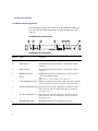
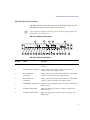
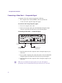
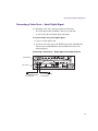
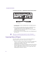
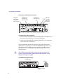
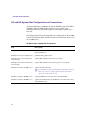
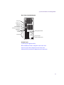
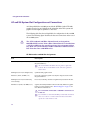
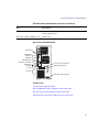
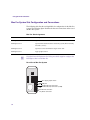
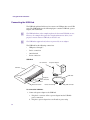
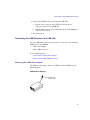
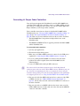
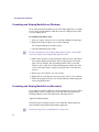
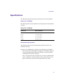
Connecting Serial and MIDI Port Devices Connecting JL Cooper Fader Controllers Your Avid system supports the FaderMaster Pro and the MCS-3000X fader controllers. Both of the fader controllers connect to a USB-to-MIDI converter that connects to a USB port on the system. See your Avid editing application Help to initialize your JL Cooper fader controllers. Fader controller connections are shown for both the MCS-3000X and the FaderMaster Pro (see “JL Cooper MCS-3000X Fader Controller Cabling” on page 40 and “JL Cooper FaderMaster Pro Fader Controller Cabling” on page 40). There are two major differences between the two fader controllers: • The MCS-3000X has a four-position switchpack that is not on the FaderMaster Pro. • The MIDI IN and MIDI OUT are in opposite positions in the MCS-3000X and the FaderMaster Pro. To connect the fader controllers: 1. Quit any open applications. 2. Shut down the Avid editing system. 3. Make sure your USB-to-MIDI converter is connected to the USB port as explained in “Connecting the USB-to-MIDI Converter” on page 38. 4. If you are cabling the MCS-3000X, set switch 4 to the ON (down) position. The switch is upside down on the MCS-3000X (see the following figure). 5. Locate two MIDI cables with 5-pin DIN connectors. n You can use the In A and Out A connector pair or the In B and Out B connector pair on the rear of the USB-to-MIDI converter. Whichever pair you use, select the corresponding port when you configure the device using the Controller Settings dialog box in the Avid editing application. For information on configuring the device, see Using the FaderMaster Pro and MCS-3000X. 6. Plug one end of the first MIDI cable into the In A connector of the USBto-MIDI converter (see “USB-to-MIDI Converter Front Panel” on page 41), and the other end of the cable into the MIDI OUT connector of the fader controller. 7. Plug one end of the second MIDI cable into the Out A connector of the USB-to-MIDI converter, and the other end of the cable into the MIDI IN connector of the fader controller. 39 Using the Avid Adrenaline 8. Make sure the button on the front of the USB-to-MIDI converter is pushed in (see “USB-to-MIDI Converter Front Panel” on page 41). JL Cooper MCS-3000X Fader Controller Cabling ON MIDI cable CTS 206-4 1 2 3 4 Switch SELECT EXPANDER USB-to-MIDI converter (rear) MIDI IN MIDI OUT MIDI IN ON POWER Out A In B Out B Out A MIDI OUT MIDI cable to In A (see “USB-to-MIDI Converter Front Panel” on page 41) JL Cooper FaderMaster Pro Fader Controller Cabling MIDI cable MIDI IN 9VDC Power _ MIDI In MIDI Out Switch In Switch Out + Out A MIDI OUT Out A In B Out B USB-to-MIDI converter (rear) MIDI cable to In A (see “USB-to-MIDI Converter Front Panel” on page 41) 40 Connecting Serial and MIDI Port Devices USB-to-MIDI Converter Front Panel IN A In A USB/ MIDI Thru IN B Button (In position) USB IN A OUT A OUT B Connecting the Yamaha 01V Mixer To connect the 01V mixer: 1. Quit any open applications. 2. Shut down the Avid editing system. 3. Make sure your USB-to-MIDI converter is connected to the USB port as explained in “Connecting the USB-to-MIDI Converter” on page 38. 4. Locate two MIDI cables with 5-pin DIN connectors. n You can use the In A and Out A connector pair or the In B and Out B connector pair on the rear of the USB-to-MIDI converter. Whichever pair you use, select the corresponding port when you configure the device using the Controller Settings dialog box in the Avid editing application. For information on configuring the device, see Setting Up the Yamaha 01V/96 or Yamaha 01V. 5. Plug one end of the first MIDI cable into the In A connector of the USBto-MIDI converter (see “USB-to-MIDI Converter Front Panel” on page 41). 6. Plug the other end of the cable into the MIDI OUT connector of the 01V mixer (see the following figure). 7. Plug one end of the second MIDI cable into the Out A connector of the USB-to-MIDI converter. 8. Plug the other end of the cable into the MIDI IN connector of the 01V mixer (see the following figure). 9. Make sure button on the front of the USB-to-MIDI converter is pushed in (see “USB-to-MIDI Converter Front Panel” on page 41). 41 Using the Avid Adrenaline Yamaha 01V Mixer Rear View MIDI IN MIDI OUT R L SREREO OUT OMNI OUT MONITOR OUT R 4 3 2 USB-to-MIDI converter (rear) L 1 DIGITAL STEREO COAXIAL OUT POWER ON IN MIDI THRU OUT TO HOST IN Out A OPTION 1/0 In B Out B OFF Out A n n MIDI cable to In A (see “USB-to-MIDI Converter Front Panel” on page 41) You must set up the 01V mixer using its front panel. See your Avid editing application Help for more setup instructions. The Yamaha 01V mixer can also be connected directly to a serial port. For information on configuring the mixer when connected to a serial port, see Setting Up the Yamaha 01V/96 or Yamaha 01V. Connecting the Yamaha 01V/96 Mixer You can connect a Yamaha 01V/96 mixer via MIDI using the same procedure described in “Connecting the Yamaha 01V Mixer” on page 41. However, Avid recommends that you use a USB connection for this mixer. For information on connecting the Yamaha 01V/96 or Yamaha 01V, see Setting Up the Yamaha 01V/96 or Yamaha 01V. Controlling a Video Deck Avid editing systems provide video deck control through a serial control connector on most decks. You can control a single deck by using an RS-232 to RS-422 serial adapter. An optional RS-232 to RS-422 serial adapter kit is available through Avid. The optional serial adapter kit that contains the following: 42 • An RS-232 to RS-422 serial adapter • Two serial cables with 9-pin male connectors at both ends Connecting Serial and MIDI Port Devices To connect a single deck to your system: 1. Locate the serial adapter kit. 2. Attach one end of a 9-pin cable to the end of the serial adapter labeled RS-232. 3. Attach the other end of the 9-pin cable to the serial port on the Avid editing system (see the following figure) or to the serial connector of the USB-to-serial adapter. n When you attach the cable to the serial port on the PC, note if you are using the COM1 or COM2 serial port. You need to select the same port in the Avid editing application. Video Deck Control Cabling RS-422 connection To video deck Serial Adapter RS-232 connection To Avid editing system 4. Attach one end of another 9-pin cable to the end of the serial adapter labeled RS-422. 5. Attach the other end of the 9-pin cable to the remote serial port of the video deck. n Place the deck in Remote mode before attempting to control the deck using the software. See the documentation provided with your deck. 43 Using the Avid Adrenaline Storage You have several storage options, including SCSI, Fibre Channel, 1394, and Ethernet. To use all the resolutions available in your Avid editing application, you might need to configure and stripe your drives. See the following topics on storage options: • SCSI Support • Fibre Channel Support • 1394 Support • Ethernet Support • Formatting and Striping MediaDrives (Windows) • Formatting and Striping MediaDrives (Macintosh) SCSI Support Avid has qualified the two SCSI channels on the rear of the xw8200 system and the built-in SCSI support on the xw8400 (see “HP xw8200 System Slot Configuration and Connections” on page 28 or “HP xw8400 System Slot Configuration and Connections” on page 26). The channels connect to a dual U320 chip on the system board. You can use the two SCSI connectors at the rear of the system and a Fibre Channel board in the xw8200 system at the same time. Avid supports the ATTO SCSI UL3D/160 LVD board in the G4 system and the G5 system. Additional boards might be supported at a later date. You can use a SCSI board and a Fibre Channel board at the same time in the G4 system or the G5 system. Documentation for connecting storage devices is included with the devices on a CD-ROM if they are purchased from Avid. Striping information can be found on the Avid Knowledge Base. n 44 Contact your Avid Sales and Product information line at 800-949-2843 for the latest storage product information. Storage Fibre Channel Support Avid provides support for local storage or Avid Unity MediaNetwork using the following Fibre Channel boards: • ATTO 2-Gb optical Fibre Channel (Model 3300, single channel) • ATTO 2-Gb copper Fibre Channel (Model 3305, single channel) 1394 Support When you are using an Avid Adrenaline and you want to use 1394 (FireWire) drives, you need a second 1394 OHCI board on a different bus segment in your Avid editing system. See your computer manufacturer’s documentation to identify a PCI bus slot that is on a different bus segment than the 1394 port used for the Avid Adrenaline. n If you use a 1394 board, it must be a “universal” PCI card and not a +5V-only board. To determine the supported 1394 boards, go to www.avid.com. Click your product line (for example, Broadcast or Video Editing) and then click your Avid application. n At this time, Avid has not qualified a FireWire 800 (or 1394b) drive to be used with Avid Adrenaline systems. For the latest qualified storage products, contact your local Avid Reseller or call the Avid Sales and Product information line at 800-949-2843 for the latest information about available drives. Ethernet Support At this time only the Alacritech 1-Gb board is supported. For supported devices and configurations, go to www.avid.com. Click your product line (for example, Broadcast or Video Editing) and then click your Avid application. n You cannot use the built-in 1394 connection and the built-in 1-Gb Ethernet for a Avid LANshare EX connection at the same time. 45 Using the Avid Adrenaline Formatting and Striping MediaDrives (Windows) To use all the resolutions available in your Avid editing application, you might need to stripe your MediaDrives. Disk drives must be configured as Dynamic if you are striping drives. To configure and stripe a drive: 1. Start your system, and log in to an account with administrative privileges. 2. Right-click the My Computer icon, and select Manage. The Computer Management window opens. 3. Click the Disk Management folder. n For more information on the Computer Management window, click the Help icon in the toolbar of the Computer Management window. 4. Make a drive Dynamic by right-clicking the disk ID section of the disk in the Computer Management window and selecting Upgrade to Dynamic disk, or Create Dynamic disk, depending upon the status of your disk. When you select a disk in the Computer Management window, the white section of the disk changes to stripes, showing that the section has been selected. 5. Repeat step 4 for each drive you want to stripe. 6. Right-click one of the Dynamic drives and select Action > Create Volume. 7. Follow the instructions in the Create Volume Wizard to finish striping the drives using NTFS format. Formatting and Striping MediaDrives (Macintosh) To use all the resolutions available in your Avid editing system, use the ATTO ExpressStripe software to stripe drives on the Mac OS X operating system. The ExpressStripe software is installed in the following location: /Applications/ExpressStripe The instructions for using the software are in a PDF file, Expressstripe.pdf, that is installed along with the ExpressStripe application. n 46 You must be logged in as an Administrator to stripe drives. Storage c Do not use the Apple Disk Utility application (in Applications/Utilities) to stripe drives. If you use the Disk Utility application, you will not be able to view the drives on the Mac OS 9 system. Additionally, Avid’s drive filtering feature will not function properly, resulting in poor performance. There are certain considerations when using striped drives on different Macintosh operating systems and when moving striped drives. Related Topics: • Using Striped Drives on Mac OS X and Mac OS 9.x Systems • Moving Striped Drives to Another System (Macintosh Only) Using Striped Drives on Mac OS X and Mac OS 9.x Systems The Avid editing software automatically recognizes drives that were striped on Mac OS 9.x. You should be able to use these drives to edit and play video. However, if you move a drive that was striped on a Mac OS X system back to Mac OS 9.x, you cannot play video from the drives on Mac OS 9.x. If necessary, you can set up your Mac OS 9.x system so that it recognizes the drives. You can then copy media files from the drive to your Mac OS 9.x drives. To set up a Mac OS 9.x system to recognize drives that were striped on a Mac OS X system: 1. Navigate to the following folder: Applications/Avid Goodies/OS 9/System Folder/Extensions 2. Copy the file ~~ExpressStripe_OS9_Enablr to the Extensions folder on your Mac OS 9 system. 3. Restart the Mac OS 9 system. The system is now able to recognize the striped drives. You can use the drives to copy media onto your Mac OS 9 drives. c Do not run a Mac OS 9 Avid editing application on the same system as a Mac OS X Avid editing system. There might be conflicts between the system files used by the two applications. 47 Using the Avid Adrenaline Moving Striped Drives to Another System (Macintosh Only) In order to move striped drives to another system, you need to be able to identify the drives that make up a particular striped set. This was easy on Mac OS 9 because the system allowed you to use the SCSI ID order when striping drives. On Mac OS X, the system does not use the SCSI ID but instead uses its internal diskn name (where n is the drive number) when creating the striped sets. You can use Avid Storage Manager or ExpressStripe to identify a striped set on Mac OS X. To use Avid Storage Manager to identify a striped set: 1. Start the Avid Storage Manager application and select View > Volumes. 2. Select the striped volume you wish to move and click Identify. The system blinks the lights on the front of the drives that make up the volume. To use ExpressStripe to identify a striped set: 1. Start the ExpressStripe application. 2. In the opening dialog boxes, select Utilities and then select Benchmark. 3. Select the striped volume you want to move and click Start. The system runs the benchmark test on the volume and shows activity on the front of the drives that make up the volume. 48 Specifications Specifications The following information provides specifications for the Avid Adrenaline: Dimensions and Weight The following table shows the dimensions and weight for the Avid Adrenaline enclosure. Dimensions and Weight Dimension Avid Adrenaline Width 17.5 in (445 mm) Height 5.25 in (132 mm) Depth 16.8 in (422 mm) Weight 29.0 lb (13.2 kg) Environmental Specifications The following table shows the environmental specifications for the Avid Adrenaline enclosure. In general, you should prepare a site that is clean and dust free. In addition: • Select a location free from significant temperature or humidity changes. A location with approximately 40 percent humidity can prevent problems stemming from electrostatic discharge. • Select a location where there is adequate space in front of and behind the system components. You must be able to connect cables and service the parts of your system; they also need adequate airflow for cooling. 49 Using the Avid Adrenaline Environmental Specifications Environment Specification Operating temperature 50°F to 95°F (10°C to 35°C) Operating humidity 5% to 95% noncondensing Storage temperature –40°F to 117°F (–40°C to 47°C) Storage humidity 5% to 95% noncondensing Electrical Specifications The following table shows electrical specifications for the Avid Adrenaline enclosure. Select your site with these electrical requirements in mind: • Make sure there are adequate power outlets for the Avid Adrenaline. This prevents the need for extension cords. • Make sure your site is away from major electrical equipment such as motors, air conditioners, or elevators. • Make sure the location is not subject to static electrical buildup. • Plug only the Avid Adrenaline and other system equipment into the power strip. Do not plug in coffee makers, radios, lights, or other non-Avid devices. Avid recommends the use of an uninterruptible power supply (UPS) appropriately sized for your system configuration. The UPS provides system protection against sudden power surges or losses that could cause you to lose your work. Electrical Specifications 50 Topic Specification Voltage 100 V ac to 240 V ac Frequency range 50 Hz to 60 Hz Watts 165 W