1
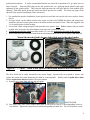
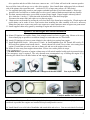
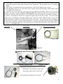
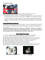
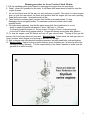
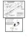
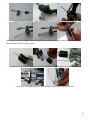
Emission-Related Installation Instruction
Manual for all Skyhawk 2 cycle models
Failing to follow these instructions when installing a certified engine in a piece of nonroad equipment
violates federal law (40CFR1068.105(b), subject to fines or other penalties as described in the Clean Air Act.
Note: Mechanical aptitude and ability is required to perform this installation. Many “do it yourself”
backyard mechanics will find this project rewarding. However, installation is sometimes best done by a
professional mechanic. A rewarding joy and challenge can be found in designing a custom installation of
your own. As with all motorized bikes it is essential that the front and rear wheels have good brakes to
ensure safe operation. Front wheels with disc brakes are a good option and may be obtained at most bicycle
shops. For a long life rear wheel axel use the Skyhawk heavy duty hub axel kit. Break in your engine
slowly with a 16-1 oil / gas mix. Remember, a quality installation and engine break in with the right oil mix
is paramount to safe usage and long term satisfaction. The engine is designed for bicycle use as described
below only. Do not use or install engine otherwise. Have fun and good luck on your motorized project.
STEP #1
Mounting Engine:
1. The engine mounts in the bike frame “Vee” above the peddle wheel sprocket. ( see above pic. )
2. Consider using Masking or Duct Tape on the front down-tube & seat tube of your bicycle to protect the
paint finish while test fitting the engine to your donor bike. If the distance between the two bars exceeds
the engine mounting span then additional spacers or welded brackets are required. Mount the engine to
the seat tube first as low as possible and then fit to the front tube. Ideal position is when the top side
drive chain is in a level horizontal position. Note; Special frames are also available made to fit engine
with no modifications. If you install the engine in a way that makes the engine’s VECI label hard to read
during normal engine maintenance, you must place a duplicate label on the vehicle, as described in
40CFR 1068.105.
SPROCKET INSTALLATION ON REAR WHEEL
44 tooth - Install on Coaster Brake wheels or any wheel
without drum brakes or disc brakes; In some cases it may be
necessary to enlarge the center sprocket hole to fit axle hub.
9 hole sprockets are made for 36 spoke wheels. For long life
it is best to use with wheels having 12 to 14 ga. Spokes;
Attention to true alignment with engine drive sprocket is
essential to keep chain from
coming off. A chain idler is
used to tighten chain if needed.
ENGINE FORWARD
MOUNT ISTALLATION:
1
Custom made idea
Custom made idea
Standard mounting to 28mm tube
Many different frame sizes and angels require
mechanical challenges to the installer when
mounting the front engine to the down tube
frame. When looking for a donor bike it is best to
compare the engine to the frame before purchase
of a new bike. Note: Seat tubes of 28 to 29 mm
work best. Attach engine to seat tube first,
position, and then
determine
front
mounting.
All
Skyhawk kits come
with a special mount
plate for large down
tubes.
Figure 2 An extra rear block is included in all kits:
Using another rear block in front may be helpful.
Note: Consult your selling dealer; he may have his own special front engine mount designed,
made and marketed separately by him.
Figure 1.
This adapter plate is included in kit.
2
Bike with large front frame tube: Use ¼” thick 1-1/8” x 2-1/2” steel plate with one hole in the center
for a bolt to go through a drilled hole in tube frame and two holes for cap screws to go into engine
block. Additional spacers maybe required depending on the donor bike.
Figure # 1
If the rear frame tube from the seat down to the pedal sprocket is too small to fit the rear engine mount, a
rubber shim can be made from an old bicycle rubber inner tube. This also helps reduce engine vibration.
After the desired engine location is determined mount the engine to frame. Lock nuts and or use of Loctite
is recommended to avoid loosening due to vibration. Note: All nuts and bolts have metric threads.
OPTIONAL ACCESSARIES
Rear tank:
Chrome Tank:
All attempts are made at the factory to have the
engine drive sprocket look like this picture: If the one
on your engine has sharp edges at the tops of the teeth
it is advisable to grind off slightly so sharp edges do
not interfere with chain operation. This is important
if the top of the engine drive sprocket is in a higher
horizontal plane than the top of the wheel sprocket.
Avoid mounting engine in a high position. Mount engine as low as possible.
Chain Wheel Sprocket Installation:
The Drive Chain Sprocket has a 36.9 mm dia. center hole and mounts on axel hub on the left side of the
rear wheel against the spokes dish side in. The sprocket must fit over the hub in a perpendicular plane with
the axle. This insures that your rear chain sprocket spins true with the rear bike wheel. *NOTE: On some
older bike axle hubs like on coaster brake models it may be required to slightly enlarge the sprocket center
hole to obtain a flush, and concentric fit next to the spokes. This is best done on a engine lathe by a
3
professional machinist.. . It is also recommended that the rear wheel be re-spooked to 12 ga. spoke wires to
insure long life. Most any Bike shop can do this operation for you. Applying thread adhesive and equal
tightening of the sprocket bolts. This keeps the chain sprocket true with axle and free from wobble while
spinning. With bike upside down spin wheel and check sprocket for wobble. The chain can jump off the
sprocket if the sprocket installation is done incorrectly.
1. For standard kit sprocket installation, locate sprocket on axel hub with curved side next to spokes, shinny
side in.
2. If not pre sliced, cut the rubber isolator to the center, in order to fit INSIDE the spokes and around axle.
Install the split steel retainer plates next to the rubber isolator and insert 9 bolts. Some kits supplied with
5 or 6 retainer plates for dual locking.
3. Secure with 9 bolts compressing the chain sprocket to the spokes. Note: Rubber isolators may be needed
on both sides of sprocket for chain alignment on some non-coaster brake bikes.
4. Chain sprocket on the wheel must align within 1/2 cm to the chain drive sprocket on the engine.
5. Wheel chain sprocket is mounted with teeth-out and shinny dished side in next to spokes. SEE FIG. #3
Mount the sprocket bight chrome dished side next to the wheel spokes
Figure #3 --- 9 hole - Chain Wheel Sprocket Installation mounted dish side inward:
The drive chain can be easily shortened to the correct length. Special tools are required to remove and
replace the master link when shortening the chain by removing links. Ideally, both the pedal drive chain
and the engine drive chain should have the same tension.
A. Remove cover plate from left rear side of engine.
MASTER LINK
B Your engine may come with a standard bike chain or with a Heavy Duty 415 chain depending on how it
was ordered. Engine drive sprockets are different depending on chain size. The 415 chain uses a wide
4
drive sprocket and the std. bike chain uses a narrow one. A 415 chain will work with a narrow sprocket
but a std. bike chain will not go over a wide drive sprocket. Note: Install chain with master link on inboard
side of the primary drive sprocket teeth. (wide tires 2.125 or larger may rub on a 415 HD chain: )
A. Use supplied spark-plug wrench to turn engine crankshaft sprocket to feed chain around it. Do not pry
sprocket with a screwdriver or similar object as drive gear is made of harden material and may fracture.
B. Fit chain, measure and remove excess links to assure proper length. Proper length is when top side of
drive chain has ¼ inch to ½” deflection with the bottom side of the chain loop tight.
Reconnect the master link, and replace cover plate on engine.
F. Chain tension can be made by moving the rear wheel back if the frame has a straight slot. If both engine and
pedal chains can be made to have equal tension then installing the idler assembly will not be necessary.
Mount the chain idler on the wheel strut if the engine drive chain cannot be made as tight as the pedal chain.
G. Install supplied chain safety guard by attaching to engine and wheel axle struts.
Ignition Coil and Engine Kill Switch installation
A) Mount CD ignition coil on bike frame, close enough to attach coil wire to spark plug. Mount as far away
from exhaust pipe as possible to avoid heat damage to semiconductors in CDI module.
B) Attach CD ignition coil wires to same identical color coded wires coming from engine.
C) Install Engine Kill Switch: Select one of 3 kinds. A. Small handlebar type: B. Throttle kill switch: C.
Kill switch on optional twist handle clutch. Attach chosen kill switch wire to white wire coming from
engine. If switch has two wires, take one to frame grd. and one to the engine white wire.
D) Route all wires away from engine exhaust heat. Secure wires with a plastic tie straps.
*!WARNING! Operation of engine without stop or kill switch installed could result in personal injury
if an emergency stop is required! The only alternate non recommended way of killing the engine is by
releasing the clutch lever with bike brakes on and engine at slowest idle.
Handle bar kill switch
Throttle cable
CDI ignition coil
Improved throttle w/swt.
Clutch cable w/spring
New style clutch lever
New style head nut
Catalytic muffler for USA is black
Properly install catalytic muffler for USA using the hardware provided in kit such that sampling of exhaust
emissions is possible after engines are installed in bicycle and placed in service.
A) Install clutch lever to left side of handlebar and attach cable end to lever. Can use twist clutch if ordered:
5
B) Squirt light wt. oil down the cable sleeve: Route clutch cable through the ball-mount on motor with the
big spring around the cable jacket and ahead of the ball mount. The big spring serves as a cable heat
shield.
C) Insert cable wire through clutch arm and attach brass cable-end and tighten screw securely.
D) With handlebar clutch lever or twist clutch in the released outward position adjust cable tension to allow
very slight play in clutch arm.
E) Activate lever a few times, and check clutch arm for slight free play again. About 1/16” free play is
desirable. Re-adjust if needed. Basics of clutch operation: The clutch lever pulls the cable that moves the
clutch arm. In turn the clutch arm pushes a rod through the motor that pushes the clutch plate. (similar to a
car clutch.) Releasing the clutch lever engages the engine torque to the drive chain. The clutch allows
engine to start, and engage or disengage engine torque to the drive chain. When the bike is in the pedal
mode the handle bar clutch lever is locked inward in the catch notch. The bike then operates in default as it
would without any engine. Periodic clutch adjustment is necessary to maintain efficient operation *NOTE:
Cut off excess cable from clutch arm, before operation, to avoid possible interference with pedals, chain, or
your legs, etc. See Figure #4.
Clutch arm:
Clutch cable
Brass stop on cable end;
Clutch cable
Figure #4
Carburetor and Throttle Installation on page 13-14
Throttle with Kill swt.
Throttle Cable
THROTTLE with kill switch:
Kill switch; one wire goes to white wire
from engine and the other to frame grd.
Drill small hole in handle bar for pin lock.
6
Fuel Tank installation
A) Attach fuel petcock to tank. Use Teflon tape to seal threads. Careful not to strip threads.
B) Mount tank on bike top crossover frame with two supplied brackets and nuts.
C) Attach fuel line from tank to carburetor. Use Permeation Certified GoodYear SAE J30-R-9 4.8mm fuel
hose obtained from local automotive stores like AutoZone. *NOTE: Filters are contained in the petcock
and in the carburetor inlet. If engine runs poorly clean the valve filter as residue from the tank may have
clogged it.. It is highly recommend that a tank liner coating be applied inside the tank before installation.
This product is available from motorcycle dealers by the trade name of “KREEM” and is made in Somis,
CA. USA.
Gas and Oil Mixture for Fuel ratio
The engine is a 2 cycle design, therefore, a gasoline/oil mixture is necessary. During the break-in period (1st
4 tanks of fuel), the ratio should be 16 to 20 parts gasoline to 1 part oil. After the break-in period, the ratio
can be increased to 20 - 25 parts gasoline to 1 part oil. In hot climates or long trips use a rich oil mixture.
!WARNING!
Remember safety first: Wipe up any spilled fuel. NEVER fuel a hot engine or
smoke while re-fueling. This could result in sudden fire, personal injury. Always move your motorized
bike at least 10 feet from any fueling area before attempting to start it. Never leave the tank fuel cap
off after fueling as rain water will contaminate the fuel and cause engine failure.
MAINTENANCE SECTION
# 1. How to Adjust Clutch if signs of slipping or squealing is encountered :
A)
B)
C)
D)
E)
F)
G)
G)
H)
Disengage clutch by pulling handle bar clutch lever inward and lock into catch lock.
Remove right side engine clutch cover and remove small locking screw on center *Clutch Adjust Nut.
Pull clutch arm on left rear engine inward. Back off *Clutch Adjust Nut ¼ turn counterclockwise.
Release handlebar clutch lever and check for slight 1/16” free-play on engine clutch arm.
Readjust *Clutch Adjust Nut as required to get required 1/6” clutch arm free play.
Tighten *Clutch Adjust Nut on clutch plate clockwise until just snug.
Then re-install small locking screw in outer edge of *Clutch Adjust Nut .
Good idea to place a small gob of grease at gear mesh area. Use grease sparingly! Then replace cover.
Squirt light grade oil down clutch cable sheathing to reduce friction and make for easy lever pull.
*Clutch Adjust Nut and Lock screw
Cutch Cover removed:
7
Maintenance
New
1 Month
Interval
seat
handle bar
chain
sprocket
300km
I
I
I/L
I
ea 1000km
I
Spark Plug
I/L
I/ C
3 Months
ea
2500kms
I
I
I/L
I
6 Months
ea
5,000kms
I
I
I/L
I/R
1 Year
I/C
I/C
R
10000kms
I
I
I/L
R
tire pressure
1
1
1 I/R
I/R
Check Crancase for leakage I
I
I
crankcase oil
N/A
N/A
N/A
N/A
N/A
Cylinder Head
I
I
fuel tank lines
I
I
I
brakes pads
I
I
I
I/R
I/R
engine bolts
I
I
I
I
Exhaust
System
I
I
Air Cleaner
I
I
R
This maintenance schedule is established by taking the monthly 1000kms as a reference.
Have your moped checked and adjusted periodically to keep in optimum
condition
Code I Inspection, cleaning and adjustment
Code C
Cleaning
Code R
Replacement
Code L
Lubrication
General Information
1. Obey all traffic regulations. Always wear a helmet while riding. Remember that you are riding a
motorized bicycle and other traffic may not be able to see you. Never operate your motorized bicycle on a
pedestrian through way or sidewalk while the engine is operating. Never unsafely operate your motorized
bicycle.
The engine is a 2 cycle design, therefore, a gasoline/oil mixture is necessary. During the break-in period (1st
4 tanks of fuel, the ratio is 16 to 20 parts gasoline to 1 part 2 cycle oil. After the break-in period, the ratio is
increased to 20 to 25 parts gasoline to 1 part oil. The engine crankshaft bearings are lubricated from the oil
in the gas mix. A rich break in oil mixture ensures bearings will not cease during engine break in period.
!WARNING! Remember safety first: Wipe up any spilled fuel. NEVER fuel a hot engine or
smoke while fueling. This could result in sudden fire, personal injury. Always move your motorized
bike at least 10 feet from any fueling area before attempting to start it. Never leave the tank fuel cap
off after fueling as rain water will contaminate the fuel and cause engine failure.
2. Open the fuel valve. Small lever pointed down with fuel line is in the open position.
3 Depress the small round cap plunger, ( Tickle button ), to prime carburetor. Located on
left side of the carburetor next to the idle adjust screw. One or two times is enough.
4. Lift choke lever to the upward position. This is the small lever on the right side of the
carburetor. All the way Up the choke is on. All the way Down the choke is off. Move
progressively downward to off position during first 30 seconds during engine warm up period.
8
Running procedure for Lever Friction Clutch Models:
5. Pull the handlebar clutch lever inward, to disengage the engine from the rear wheel.
6. Pedal; (down hill if possible for first start) A mid frame bike wheel stand is helpful to start the
engine in place.
7. Let out the clutch lever all the way out and continuing to pedal. The result is a direct engine
hook up with the rear wheel via chain and sprocket and the engine will now start spinning,
Pedal until motor starts. Accelerate slowly at first..
8. Twist throttle to increase speed, reverse twist throttle to decrease speed. To stop,
disengage clutch and apply brakes. To accelerate, pedal and release clutch while
opening throttle.
9. If the rpm needs adjusting, turn the idle adjust screw (left side of carburetor) in or out
slowly to obtain the proper idle speed of about 1400 rpm +/- 100 rpm
To correctly break the engine in, Do not exceed 15 mph or 30 min. continual running
for the first 50 miles during engine break in. Engine will develop more power after break in.
10 To stop the engine, push Kill switch and turn off gas valve at tank. Turning off the gas will
prevent fuel from being siphoned from tank. Warning Note: Never leave the tank gas valve in
“open” position” when engine is not running or the bike is in storage.
11 After or before each ride check all mounting fasteners, including head bolts, axle and brakes.
12. Warning Note: Engine lock up or piston seizure due to improper gas / oil mixture will not be
covered by factory warranty. This the responsibility of the owner / operator to make sure the
gas and oil is mixed correctly.
9
10
11
12
CNS CABLE HOOK UP
PROCEDURE
Remove top:
Disconnect choke cable from lever; slide choke cable into top plate from reverse side.
13
Lock lead anchor into place; Slide choke sheathing back on and hook up lever as shown
Slide throttle cable into top plate. Install big spring and collapse with fingers to hook cable anchor into
plastic throttle slide then release spring.
Finished hook up ready to slide back into carb. with Plastic slide slot alignment to carb. alignment
.
Install screws and tighten down secure making sure gasket seats correctly on carb:
14
15