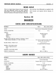
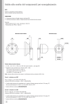
1
80—TRANSMISSION
CHRYSLER SERVICE MANUAL
Install the new " 0 " ring in the ferrule groove.
Lubricate the small bore of the column jacket support (for cylinder head ferrule).
Install the jacket support assembly over the worm
shaft carefully engaging the cylinder head ferrule
and " 0 " ring, making sure the reaction rings enter
the groove in the jacket support assembly.
Align the parts on power train so the valve lever
hole in the center bearing spacer is 90° counterclockwise from the piston rack teeth and lock all
parts to the worm shaft by entering a suitable drift
through the jacket support and worm shaft groove.
Continue with Operation 18 — Reassembly of the
Steering Gear as described in the Steering Section
of the 1958 Chrysler and Imperial Service Manual,
D-16350.
Section XI
TORQUEFLITE TRANSMISSION
The servicing of the 1959 TorqueFlite Transmission
is the same as that of the 1958 Models as described
in the 1958 Chrysler and Imperial Service Manual,
with the following exceptions.
FRONT CLUTCH (8-LEVER) DISASSEMBLY
(REFER TO FIG. 115)
Remove the input shaft fiber thrust washer (A). Remove snap ring (B). Remove input shaft (C) from
retainer (R). Invert retainer (R), remove driving
discs (D), plates (E), pressure plate (F) and hub
(G).
Install spring compressor, Tool C-3533 and compress spring retainer (I). Using pliers, Tool C-3301,
remove spring retainer snap ring (H).
After removing compressor, Tool C-3533, remove
spring retainer (I), spring (J), levers (L), lever
retainer (K), cushion spring washer (M), and cush-
ion spring (N) from retainer (R). With a twisting
motion, remove piston (Q) from retainer (R).
Inspection (Fig. 115)
The inspection procedure is the same as for the 1958
model transmissions.
Assembly (Fig. 115)
Lubricate and install inner (rubber) seal ring (T)
on hub of retainer (R). Make sure lip of seal is facing rear of retainer and seal is seated in groove.
Lubricate and install outer seal ring (S) on piston
(Q) with lip of seal towards rear of piston.
Place piston assembly in retainer (R) using a
twisting motion to seat piston in bottom of retainer.
Install cushion spring (N) with dished side (concave) facing piston (Q). (Fig. 116).
Place washer (M) with chamfer towards front of
.020"-.040"
INSTALL WASHER
WITH CHAMFER
ON THIS SIDE
Fig. 115 — Front Clutch Assembly
1.
2.
3.
4.
5.
6.
7.
8.
9.
10.
Thrust Washer
Snap Ring—Large
Input Shaft
Driving Discs
Clutch Plates
Pressure Plate
Driving Disc Hub
Snap Ring-Small
Piston Return Spring Retainer
Piston Return Spring
11.
12.
13.
14.
15.
16.
17.
18.
19.
20.
Piston Lever Retainer
Piston Lever (8)
Cushion Spring Washer
Cushion Spring
Oil Seal Ring-Small
Oil Seal Ring-Large
Piston
Piston Retainer
Piston Seal Ring-Large
Piston Seal Ring—Small
Fig. 116 —Installing Cushion Spring
TRANSMISSION—81
CHRYSLER SERVICE MANUAL
retainer (R).
Place lever retainer (K) over hub of piston and
install levers (L), as shown in Figures 116 and 117.
Install return spring (J) over hub of retainer
(R) and position spring retainer (I) and snap ring
(H) on spring (J). Using compressor, Tool C-3533,
compress return spring (J) sufficiently to seat snap
ring (H) with pliers, Tool C-3301. Remove compressor tool.
Install pressure plate (F) (smooth side up) in retainer (R). Install discs (D) and plates (E) by first
placing one of the discs (D) in retainer (R) followed by a steel plate (E). Repeat this procedure
until all discs and plates have been installed.
CHECKING CLUTCH CLEARANCE
Clutch clearance can be measured as described in the
1958 Chrysler and Imperial Service Manual.
NOTE: If Part No. 1732114 or Part No. 1824319
are not available, clearance can be adjusted by using
the front clutch cushion spring retaining plate (used
in four lever clutch assembly) Part No. 1736393,
and following the same procedure as previously outlined for obtaining clearance with the following important exception: Inasmuch as the front clutch cushion spring retaining plate (Part No. 1736393) is
thinner and considerable less rigid, care must be
exercised when checking clearance with the feeler
gauge to prevent springing the plate and hereby obtaining a false reading on pack clearance.
Install hub (G). Install input shaft (C) by placing input shaft and retainer assemblies in an arbor
press with the rear of retainer (R) resting on a suitable support. Make certain ball check (at rear of reLFVFR RFTA'-NFR
CUTCH
RL1AINER
CUSHION
SPRING
FRONT
CtUTCH "FEED*
Fig. 118 — Reaction Shaft
tainer) does not contact support during pressing
operation.
Press input shaft (C) into retainer until snap
ring (B) can be installed. Remove assembly from
arbor press (or remove "C" clamps — if used) and
place thrust washer (A) over input shaft (C) and
against thrust surface on input shaft flange.
REACTION SHAFT (CAST IRON) (FIG. 118)
The reaction shaft, formerly made of aluminum, is
now made of cast iron.
Transmissions equipped with the new reaction
shaft have the letter "R" (or letters following alphabetically) on the rightside pan rail.
The cast iron reaction shaft can be used in early
model transmissions provided the late production
input shaft assembly is installed at the same time.
EXTENSION HOUSING (FIG. 119)
The extension housing has been redesigned to accommodate the bronze bushing, which has replaced
the ball bearing, and also the smaller oil seal.
SERVICING THE OIL SEAL
The oil seal can be serviced with the transmission
THRUST WASHER
58x753
Fig. 117 — Clutch Retainer
Fig. 119 — Extension Housing
82—TRANSMISSION
CHRYSLER SERVICE MANUAL
installed in the vehicle.
loosen, cable clamp bolt on hand brake support. Disengage the ball end of the cable from operating lever
and remove cable from brake support.
Removal
Disconnect the front universal joint. Apply the hand
brake (or use wrench, Tool C-3281) and remove the
propeller shaft flange nut and flat washer. Release
hand brake (or remove wrench) and install puller,
Tool C-452 (if necessary). Remove the propeller
shaft flange and brake drum assembly. Remove the
transmission brake support grease shield spring
(small one). Remove brake support grease shield
from extension. If screwdriver or sharp instrument
is used in performing this operation, care must be
exercised not to damage the neoprene sealing surface at bottom of shield. Install puller, Tool C-3690,
and remove the oil seal.
Installation
Using driver, Tool C-3691, install seal (metal portion of seal facing in) until driver bottoms on extension. Install brake support grease shield on extension. Indent on grease shield must match groove
in extension for correct positioning. Also, shield
must be located on extension far enough to permit
installation of spring. Install brake support grease
shield spring (opening in spring toward adjusting
sleeve). Make sure spring is properly seated in
groove. Install propeller shaft flange and drum assembly. Install propeller shaft flange, flat washer
and nut. Apply hand brake (or use wrench, Tool
C-3281) and torque the propeller shaft flange nut to
175 foot-pounds torque. Connect front universal
joint and torque tighten the nuts from 33 to 37 footpounds.
EXTENSION BUSHING
Removal
Drain approximately two quarts of fluid from transmission. Disconnect front universal joint. Apply
hand brake (or use wrench, Tool C-3281) and remove propeller shaft flange nut and flat washer. Release hand brake (or remove wrench, C-3281). Using puller, Tool C-452, remove the brake drum and
flange assembly.
Remove the brake support grease shield spring
and remove grease shield from extension housing.
If screwdriver or sharp instrument is used in performing this operation, care must be exercised not
to damage the neoprene sealing surface at bottom
of shield. Install puller, Tool C-3690, and remove the
oil seal.
Remove brake adjusting screw cover plate and
Disconnect speedometer cable and housing from
extension and remove speedometer drive pinion and
sleeve assembly. Proceed to remove extension housing assembly from transmission case as outlined in
the Chrysler and Imperial service manual. If care is
exercised, it is not necessary to remove hand brake
support and shoe assemblies from extension to replace the bushing or seal.
With the large diameter end of the extension housing resting on a smooth, clean surface, proceed to
drive the bushing from the housing using driver,
Tool C-3689.
Installation
Place a new bushing on installing Tool C-3692.
NOTE: When positioning bushings and tool on extension housing prior to the driving operation, make
definitely sure that lubrication hole in bushing will
index properly with lubrication hole in extension
housing, when bushing has been driven into position.
Pulling the tool out of the bushing seats the bushing and removes any slight irregularities. The installed bushing should not be removed.
Using driver, Tool C-3691, install oil seal (metal
portion of seal facing in) until driver bottoms on
extension. Install brake support grease shield. Indent on shield must match groove in extension for
correct positioning. Also, shield must be located on
extension far enough to permit installation of
spring. Install brake support grease shield spring
(opening on spring toward adjusting sleeve).
Install the extension housing assembly as described in the 1958 Chrysler and Imperial Service
Manual.
HAND BRAKE DRUM—FLANGE ASSEMBLY
The hand brake drum and flange assembly now contacts a shoulder (Fig. 119) on the output shaft instead of the race of a ball bearing. The flange assembly has been slightly modified.
This modification now provides for a straight (instead of a bevel as formerly used counterbore within the flange assembly.
OUTPUT SHAFT SUPPORT
To provide lubrication for the new tabbed thrust
CHRYSLER SERVICE MANUAL
UNIVERSAL JOINTS AND PROPELLER SHAFT—83
washer (Fig. 119) which must be used in conjunction with the new design output shaft and extension
housing, a redesigned output shaft support is also
required.
THRUST WASHER
The new output shaft support (Fig. 120) has redesigned webs which serve to act as locating guides
for the tabs of the thrust washer.
NOTE: When installing the tabbed thrust washer,
install with tabs facing output shaft support. The
proper positioning of tabs, in relationship to webs,
is obtained when minimum clearance exists between
tabs of washer and output shaft support webs. This
means that it may be necessary to rotate the washer
to find the location which provides minimum tab-toweb clearance.
Fig. 120 — Output Shaft Support
MAINTENANCE, ADJUSTMENTS—TESTS
In investigating any transmission malfunction, first
make certain that all external adjustments have been
made correctly.
Check fluid level on any transmission complaint.
Erratic performance of the transmission, particularly its shifting performance, can often be traced to
incorrect fluid level. Fluid level can be checked with
fluid either hot or cold (oil pan is hot to touch), the
engine running at normal idle speed, the transmission in neutral, and the hand brake applied. Make
sure cap on dipstick is not loose. Cap acts as a stop
and if loose, will give a false reading on dipstick.
All five push buttons should be operated slowly, returning to the neutral button each time. The fluid
level should be as follows:
(a)
Fluid
pint"
bring
Transmission hot; engine idling in neutral.
should be between the "F" and the "add 1
marks. Fluid should be added or removed to
the level between these two marks.
(b) Transmission cold (100°F or below) ; engine
idling in neutral. Fluid should be between the "add
1 pint" and a point "i/2 inch" below the "add 1 pint"
mark. Fluid should be added or removed to bring
the level between these two positions.
CAUTION: Do not add oil unless the level is below
the specified range. Only automatic transmission fluid
(type A) should be used. Overfilling leads to foaming, and loss of pressure, resulting in erratic shift
performance. The addition of special compounds to
transmission fluids for which improved performance,
elimination of sludge, or reduction of fluid leakage
may be claimed IS NOT RECOMMENDED.
CAUTION
To prevent dirt from entering the transmission,
make sure the oil level indicator cap is seated properly on the filler tube.
THROTTLE LINKAGE ADJUSTMENTS
Throttle linkage adjustment remains essentially the
same as for 1958 model vehicles, with the following
exception:
Placing a pin through an appropriate slot and
hole (in lever and bracket) will set the correct angle
of the lever for easier adjusting of the entire throttle linkage.
BAND ADJUSTMENTS
The band adjustments are performed in the same
manner as described in the 1958 Chrysler and Imperial Service Manual, except the kickdown band
adjusting screw is backed off 2% turns, and the
low and reverse band adjusting screw is backed off
2% turns.
UNIVERSAL JOINTS AND PROPELLER SHAFT
The universal joints and propeller shaft servicing
procedure will remain the same as outlined in the
1958 Chrysler and Imperial Service Manual, D16350.
84—WHEELS AND TIRES
CHRYSLER SERVICE MANUAL
Section XII
UNIVERSAL JOINTS
AND PROPELLER SHAFTS
DATA AND SPECIFICATIONS
MODELS
Propeller Shaft
Number used
Diameter—All Cars
With TorqueFlite Transmission
Diameter with Air Conditioning
and TorqueFlite Transmission
Length
Centerline to Centerline of "U
Joints with TorqueFlite Trans
Flange to Flange Length
With TorqueFlite Transmission
Lubrication
Universal Joints
Type
MC-1, MC-2
MC-3
MY-1
1
1
*2
2.75 in.
2.75 in.
2.75 in.
2.75 in.
2.75 in.
2.75 in.
58.96
58.96
63.64
60.69
60.69
**Prepack
63.56
(Front) Ball and Trunion
(Rear) Cross Type
Bearing
Type
*Rear propeller shaft tube is rubber insulated.
**Every 20,000 miles.
Cross Type
(3 Joints)
Anti-Friction Roller
Section XIII
WHEELS AND TIRES
DATA AND SPECIFICATIONS
MODELS
WHEELS
Type
Rim
Size
Flange Type
No. of Nuts to Attach Wheel
Stud Hole Circle (Diameter)
Stud Size
TIRES
Type
Cord Material
Size
TIRE PRESSURE—Cold
Pounds—Front
Rear
MC-1
....
MC-2
MO-3
MY-1
14x5H
K
5
4^
V2 x 20
Steel Disc
Drop Center—Safety Wheel
14x6
14 x 6J^
K
K
5
5
4^
4^
Y2 x 20
Y2 x 20
14x7
K
5
53^
% x 18
Rayon
8.00x14
Super Soft Cushion Tubeless
Rayon
Rayon
8.50x14
9.00x14
Rayon
9.50x14
24
22
22
22
22
22
22
20