1
APPENDIX 2. INTEGRATOR (IT) BLOCK
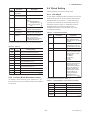
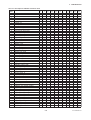
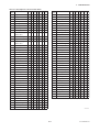
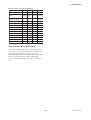
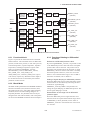
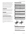
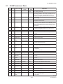
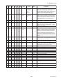
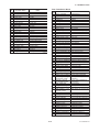
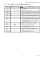
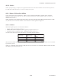
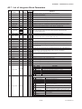
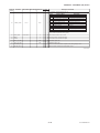
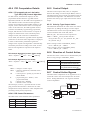
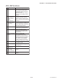
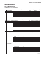
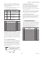
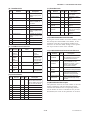
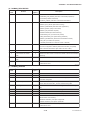
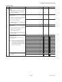
A2.7 List of Integrator Block Parameters
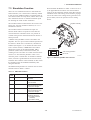
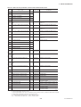
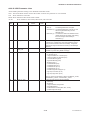
1
View
Write
Definition
Mode 1 2 3 4
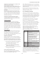
Block Tag
Information relating to this function block, such as block tag,
BLOCK_HEADER TAG: "IT" =o/s
DD revision, execution time
--ST_REV
0
2 2 2 2 The revision level of the set parameters associated with the Integrator block
2
TAG_DESC
Nu11
3
STRATEGY
1
4
ALERT_KEY
1
5
MODE_BLK
6
BLOCK_ERR
7
TOTAL_SP
Index
0
8
Parameter
Name
Initial
Value
Stores comments describing tag information.
2 The strategy field is used by a high-level system to identify the function block.
1 Key information used to identify the location at which an alert occurred
---
1000000.0
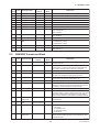
OUT
MAN
4
4
Integrator block mode. O/S, MAN, and AUTO are supported.
2
2
Indicates the active error conditions associated with the function block in bit strings.
4
4
The setpoint of an integrated value or a start value for counting down
5
5
The block output
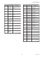
1000000.0
0.0
m3(1034)
0
11
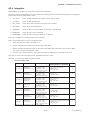
Set scaling for output display. This does not affect operation of the function block.
It is used for making memos.
2
The parameter for checking if various operations have been executed
9
OUT_RANGE
10
GRANT_DENY
0
11
STATUS_OPTS
0
2
OS
12
IN_1
0.0
5
5
13
IN_2
0.0
5
5
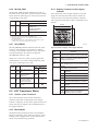
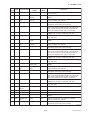
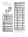
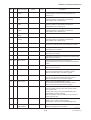
Allows you to select a status-related option.
The Integrator block uses "Uncertain if Man mode" only.
Inputs flow (Rate, Accum) signals from the AI block or PI block.
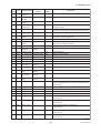
14
OUT_TRIP
0
2
2
An output parameter informing the user that the integrated value has exceeded the setpoint
15
OUT_PTRIP
0
2
2
An output parameter informing the user that the integrated value is reaching the setpoint
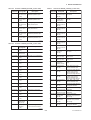
16
TIME_UNIT1
sec(1)
MAN
1
17
TIME_UNIT2
sec(1)
MAN
1
18
UNIT_CONV
1.0
19
PULSE_VAL1
Set the time unit of the rate (kg/s, lb/min, kg/h ... etc.) of the
corresponding IN.
4 Specify the unit conversion factor for standardizing the unit of IN_2 into that of IN_1.
1.0
MAN
MAN
4 Set the factor for converting the number of pulses for the corresponding
4 IN into an appropriate engineering unit.
20
PULSE_VAL2
1.0
21
REV_FLOW1
0
2
2
22
REV_FLOW2
0
2
2
Selector switch used to specify the fluid flow direction
(forward/reverse) with respect to the corresponding IN
23
RESET_IN
0
2
2
The parameter that receives a reset request from an external block to reset the integrated values
24
STOTAL
0.0
4
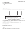
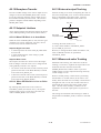
Indicates the snapshot of OUT just before a reset.
25
RTOTAL
0.0
4
Indicates the integrated value of the absolute values of the increments if the input status is "Bad."
26
SRTOTAL
0.0
4
Indicates the snapshot of RTOTAL just before a reset.
0.0
4
Indicates the snapshot of TOTAL_SP just before a reset.
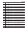
27
SSP
MAN
4
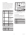
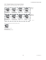
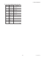
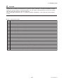
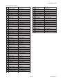
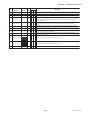
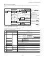
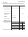
Integration Type Setting
28
INTEG_TYPE
UP_AUTO
(1)
1
Value
1
2
3
4
5
6
7
Name
UP_AUTO
UP_DEM
DN_AUTO
DN_DEM
PERIODIC
DEMAND
PER&DEM
Description
Counts up and is automatically reset when TOTAL_SP is reached.
Counts up and is reset as demanded.
Counts down and is automatically reset when "0" is reached.
Counts down and is reset as demanded.
Counts up and is reset at periods specified in CLOCK_PER.
Counts up and is reset as demanded.
Reset periodically or as demanded.
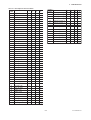
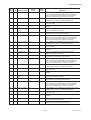
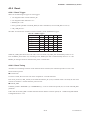
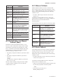
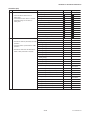
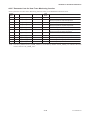
Specifies an integration optional function.
bit
0
1
2
3
29
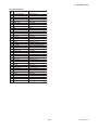
INTEG_OPTS
0ⴛ0004
2
Option Name
Input 1 accumulate
Input 2 accumulate
Flow forward
Flow reverse
4
Use uncertain
5
Use bad
6
Carry
7
Add zero if bad
8
Confirm reset
Description
Selects Rate or Accum input of IN_1.
Selects Rate or Accum input of IN_2.
Integrates forward flow (interprets reverse flow as zero).*
Integrates reverse flow (interprets forward flow as zero).*
Uses an input value of IN_1 or IN_2 whose status is "Uncertain"
regarding it as a value of "Good."
Uses an input value of IN_1 or IN_2 whose status is "Bad" regarding
it as a value of "Good."
Carries over an excess exceeding the threshold at reset to the next
integration. (Note that this does not apply to UP_AUTO or DN_AUTO.)
Interprets an increment as zero if the status of the increment is "Bad."
After a reset, rejects the next reset until "Confirm" is set to
RESET_CONFIRM.
Generates an alert event at reset.
9 Generate reset event
10ⵑ15 Reserved
* If both forward and reverse flows are enabled or disabled, both forward and reverse flows are integrated.
TA0206-1.EPS
A-19
IM 01C25R03-01E