1
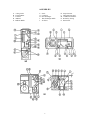
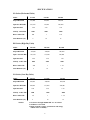
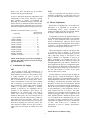
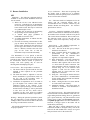
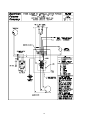
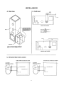
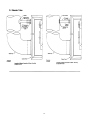
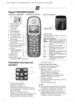
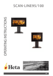
Heating
Products
Commercial
Furnace
Installation
And
Operator ’s
Manual
Nov-99
Cox systems are shipped “ready to use”. All
necessary standard equipment, controls, and wiring
are packaged with the heating systems.
Use the supplied furnace and burner manual,
together, to install the system.
Employ qualified, experienced installers, to
insure the safe and efficient operation of your
heating system.
TABLE OF CONTENTS
PACKING PROCEDURE…………2
SEQUENCE OF OPERATION…….. 8
FURNACE ASSEMBLY
DRAWINGS ….…………………..3
MAINTENANCE………………….. 9
WIRING DIAGRAM……………….10
FURNACE SPECIFICATIONS..…4
MISCELLANEOUS………………..11
A. FILTER RACK ………………..11
B. DRAFT HOOD ……………….. 11
C. OIL BURNER BLAST TUBE
LOCATION ………………….11
D. BLEEDER TUBE …………….. 12
CLEARANCES……………………5
INSTALLATION INSTRUCTIONS
A. GENERAL ...…………………..5
B. FLUE………...…………………5
C. COMBUSTION AIR
SUPPLY ……………………… 6
D. BLOWER ADJUSTMENT…… 6
E. BURNER INSTALLATION…. 7
PACKING
1 – Package Prewired and tested furnace assembly:
1- Heat exchanger/combustion chamber and
casing
1- Blower and pulley
1- Motor and pulley
1- Belt (2 on dual drives)
1- Instruction envelope and (2) wiring diagrams
1- Fan limit installed
1- Oil burner mounting flange
1 – PackageGas or oil burner:
1- Oil or gas burner and controls
1- Oil nozzle
1- Instruction manual and literature
1- Gas burner mounting flange
1 – PackageDraft control or draft hood
NOTE: Actual packing may vary according to sizes, weights, models, custom jobs, etc. Optional
equipment may or may not be packed separately.
FOR YOUR SAFETY
FOR YOUR SAFETY
If you smell gas:
1. Open windows
2. Don’t touch electrical switches
3. Extinguish any open flame
4. Immediately call your gas supplier.
Do not store or use gasoline
or other flammable vapors
and liquids in the vicinity of
this or any other appliance.
DO NOT DESTROY THIS MANUAL
Please read carefully and keep in a safe place for future reference.
2
ASSEMBLIES
A.
B.
C.
D.
E.
Casing Jacket
Fan and Motor
Felt Pad
Radiator
Radiator Baffle
F.
G.
H.
I.
J.
Stack
Connector
Heat Exchanger
Heat Exchanger Baffle
Air Tubes
3
K.
L.
M.
N.
O.
Inspection Port
Fiberglass Rope Seal
Combustion Chamber
Refractory Lining
Burner Port
SPECIFICATIONS
SO Series (Horizontal Units)
Model
SO-225
SO-300
SO-400
Output BTU/HR
225,000
300,000
400,000
Input-Gas BTU/HR
281,250
375,000
500,000
2.00
2.50
3.50
2400
3000
4400
Blower Motor HP
3/4
1
1-1/2
Stack Diameter (in.)
9
10
12
Input-Oil GPH
CFM @ .33WC ESP
HO Series (High-Boy Units)
Model
HO-225
HO-300
HO-400
Output BTU/HR
225,000
300,000
400,000
Input –Gas BTU/HR
281,250
375,000
500,000
Input-Oil GPH
2.00
2.50
3.50
CFM @ .33 WC ESP
2400
3400
4400
Blower Motor HP
3/4
1
1-1/2
Stack Diameter (in.)
9
10
12
LO-Series (Low-Boy Units)
Model
LO-225
LO-300
LO-400
Output BTU/HR
225,000
300,000
400,000
Input-Gas BTU/HR
245,000
375,000
500,000
Input-Oil GPH
2.00
2.50
3.50
CFM @ .33 WC ESP
2400
3400
4800
Blower Motor HP
3/4
1
1-1/2
Stack Diameter (in.)
9
NOTES:
10
12
1. Gas burner through 400,000 BTU are AGA listed.
2. Oil Burner is UL listed.
3. Rights retained to change specifications and ratings
without notice or liability.
4
Area of the ventilating opening into the furnace
room shall be not less than twice the area of the flue
outlet.
CLEARANCES
Unless materials used in building construction,
and/or application of the heating equipment are of
such a nature that local authorities to require
otherwise, the clearance about the furnace should be:
Ready access shall be provided for all electrical
components in service.
Draft regulator shall bear the listed marking.
ABOVE-6”, SIDES AND REAR-6”, FRONT-48”,
FLUE PIPE-18”.
The combination fan and limit control shall bear the
control listee’s name and listed marking.
WARNING: LO Models must be placed on noncombustible flooring only.
The safety control shall bear the control listee’s
name, listed markings and group designation.
SO (Horizontal) clearances
May be installed in an alcove with the following
clearances to unprotected combustible material:
6” above furnace casing, bonnet or plenum.
6” above horizontal warm air duct within 6” of
furnace.
48” from front of furnace.
18” from flue pipe in any direction.
6” from back of furnace.
6” from right side of furnace.
6” from any side of plenum.
6” from floor.
SO-300 and SO-400 “Air filters shall not be
mounted on the unit or in the air duct system.” UL
ONLY.
INSTALLATION
A. General
1.
2.
3.
4.
5.
6.
7.
When burner is furnished with separate flange,
caution should be used to insure the air tube
penetrating the chamber to within ½” of the
inside chamber surface. (Don’t push in too
far).
Wire burner as per wiring diagram. One
diagram is fixed to the inside of the blower door
and a copy is placed with this manual.
See installation and operation instructions for
blower drive adjustment in D.5.
OIL MOTOR according to instructions on
motor.
Suspend SO units by means of inserting hanging
rods through hanging lugs on furnace. Mount
LO models on non-combustible floor only.
Must be installed according to NFPA standards
for installation of oil burning equipment.
Pamphlet No.31 or NO. 54 for gas.
Must be installed according to Building Code
Standards for the installation of heat producing
appliances:
heating,
ventilating,
airconditioning, warm air heating and ventilating
systems.
8.
Must be installed according to NFPA standards
for the installation of air-conditioning, warm air
heating and ventilating systems.
9.
Air requirement into the furnace room for
satisfactory combustion is an area not smaller
than twice the cross sectional area of the flue
pipe. See burner manual.
B. Flue
The chimney must be in good condition without
cracks or openings or obstructions in the flue and of
sufficient height to prevent a down draft. Before
installing an oil burner, the smoke pipe and chimney
should be thoroughly cleaned and repaired if
required.
Minimum recommended chimney sizes: Oil
Two gallons of oil per hour and under …..8”x8”
Two to three gallons of oil per hour…8”x12”
Over three gallons of oil per hour….12”x12”
All manual dampers should be removed from the
smoke pipe before an oil burner is installed. For best
results the draft should be preferably from .02 to .03
inches at the inspection door and from .05 to .06
5
inches at the stack. The draft may be accurately
measured with any good draft gauge.
GAS
Excessive draft causes high stack temperatures and
consequently a waste of fuel. Therefore, a reliable
draft regulator is strongly recommended for
practically all installations. Proper, uniform draft
insures efficient, economical operation of the burner.
A good draft regulator will usually pay for itself in a
short time through a substantial savings in fuel costs.
D. Blower Adjustment
Fresh air requirement into the furnace room for
satisfactory combustion is 1 square inch of free area
for each 1,000 BTU input and a minimum of 100 sq.
in.
Because the Cox Heating unit is so versatile in its
application, it is impossible to be specific in
recommending blower speed. Obviously, the
quantity and quality of the duct work and the manner
in which it is applied affects the air delivery.
Minimum recommended chimney sizes: Gas
Draft Hood &
Input/hour
Flue Pipe Size
To adjust blower speed to the applied conditions, it
is recommended that the thermostat be set at highest
setting to gain prolonged burner operation. By
means of thermometers, adjust the blower speed
until the temperature rise through the unit is equal to
75 degrees – 80 degrees (difference in temperature
between air entering and leaving the unit).
Up to 120,000…………………………... 5”
120,001-180,000………………………….. 6”
180,001-250,000………………………….. 7”
250,001-320,000………………………….. 8”
320,001-410,000………………………….. 9”
410,001-510,000………………………….. 10”
510,001-610,000………………………….. 11”
610,001-730,000………………………….. 12”
730,001-860,000………………………….. 13”
860,001-1,000,000………………………... 14”
1,000,001-1,140,000……………………… 15”
Unless the temperature of the air entering the units
is excessively high (75 degrees or more) such
adjustment will result in continued burner operation
with a high limit setting of 180 degrees to 200
degrees. Should it be impossible to gain an 85
degree temperature rise through the unit, the
indications are that the fan is running too fast for the
intended application of the furnace. Should the air
being supplied to the unit be at a temperature higher
than 95 degrees, the indications are that the heated
air leaving the unit is being short circuited back to
the unit. The remedy is revision of the supply
system, return system, or both.
NOTE: If the flue pipe exceeds 10 ft. in length, or
contains more than 2 elbows use next size larger
pipe and draft hood.
C. Combustion Air Supply
OIL
Do not install in rooms with insufficient air to
supply combustion. Occasionally, it is necessary to
install windows or louvers in a door to these rooms,
to obtain sufficient air and to prevent less
atmospheric air pressure in the room. If there is a
lack of combustion air, the burner flame will be
yellow and formation of soot will occur in heating
unit. In buildings of conventional frame, brick or
stone construction without utility rooms, basement
windows, or stair doors, infiltration is normally
adequate to provide air for combustion and for
operation of the barometric draft control. For
installation in an enclosed utility room with an
outside wall, a fresh air opening to the outside
should be made with a free cross sectional area of
twice the area of the flue outlet of 100 sq. inches for
each gallon nozzle size (Example: 10x10 for 1.00
GPH). For each 1,000 feet above sea level, increase
the fresh air opening by at least four percent. The
room should be isolated from any area served by
exhaust fans. Do not install an exhaust fan in this
room.
In many instances, it will be possible to adjust the
blower speed by setting the thermostat to highest
setting (for purposes of continued burner operation
during adjustment) and limit control 180 degrees to
200 degrees, increasing then, the blower speed until
the burner no longer cuts out on high limit. Should
the burner cycle on high limit setting, indications are
that the duct static pressure is higher than intended
by the manufacturer, or the temperature of the air
being supplied the unit is excessive. This latter
method is not as reliable as that described in the
foregoing paragraph which will be applied by the
better qualified installer. Should the blower motor
cut out, indications are: inadequate firing rate, fan
off setting too high, overload of motor, too high
temperature air supplied to the unit or a combination
of same. Duct heaters have a minimum air
requirement as given in “Furnace Specification”
Section Chart.
NOTE: Do not exceed motor rating.
6
Air for Combustion – There must be openings into
the furnace room to admit free air to maintain
combustion, minimum opening of not less than twice
the area of flue outlet of furnace.
E. Burner Installation
OIL
Equipment – The following equipment shall be
available on each oil burner installation before the
tests are started:
1) Where the oil rate is not indicated on the
nozzle tip, a suitable device for determining
the rate in terms of gallons per hour fed to the
burner shall be used. This may be in the form
of a graduated glass vessel.
2) A suitable flue gas analyzer for determining
the percentage of CO2 in the flue gases.
3) A suitable draft gauge graduated in
hundredths of an inch of water.
4) A suitable thermometer to indicate the fluegas temperatures.
5) Provision for inserting a thermometer in flue
pipe as follows: Not more than 12” from the
furnace outlet, measured on the center line of
the flue pipe, there shall be a hole not more
than ½” diameter, located at the side of the
pipe on the center line so that the
thermometer may be inserted horizontally.
Size – The burner shall be of adequate size for the
furnace and the connected heating load as
recommended on the oil burner certificate by the
installer. Models and Firing Rate : See “Furnace
Specification” Section.
Certificate – Following installation of the burner,
certain test data shall be obtained and recorded by
the installer on the oil burner certificate to be placed
with each oil burner installation. The test shall cover
the following points: CO2 in the flue gas by
analysis, draft, stack temperature, firing rate, and
smoke.
Requirements – The standard requirements as
approved by the industry as follows:
1) CO2 – The CO2 in the flue gas by analysis
shall not be less than 8%.
2) Draft - The draft shall be in accordance with
specifications
in
the
manufacturer’s
installation manual. An automatic draft
regulator or its equivalent is required.
3) Stack Temperature – The stack temperature
shall be measured on the furnace side of
automatic draft regulator and not more than
12 inches from the smoke connection. The
stack temperature shall be measured at the
certified firing rate. If an automatic draft
regulator is built into the furnace, such
regulator shall be closed when the stack
temperature is measured.
4) Firing rate – The firing rate shall be based on
the burner manufacturer’s recommendation
for the existing total connected load. Burner
shall be fired at that rate.
5) Smoke – During the above test, there shall be
no visible smoke at the chimney.
6) Installation Manual – The burner shall be
installed in accordance with manufacturer’s
installation manual.
The thermometer is to be placed so that the
sensitive element is one fourth of the pipe diameter
from the far side of the flue pipe. The opening around
the thermometer shall be sealed to prevent air
leakage. This same opening may be used for
checking draft and sampling flue gases.
Test Procedure – The test procedure is as follows:
1) The burner shall be operated and the fuel rate
adjusted to that required for the particular
installation.
2) The draft then shall be adjusted to meet the
burner manufacturer’s specifications, both over
the fire and at the breeching. Refer to
“Installation Instructions” Section, B.
3) Combustion air adjustments are to be made to
give the highest CO2 without visible smoke
(unburned carbon) at the chimney. If the
minimum required percentage of CO2 cannot be
obtained in the breeching, it will be permissible
to take CO2 over the fire, which will be
acceptable. In this event, both CO2 readings
shall be recorded after 10 minutes of operation.
Fuel Tank Connections – Pipe connections between
fuel tank and the oil burner should be made with 3/8”
copper tubing and brass fittings, however, galvanized
pipe is quite satisfactory. All joints should be sealed
with key paste or other good oil resisting compound,
and pulled up tight. Where fuel tank is installed in a
basement, a one-pipe system to the burner will be
found entirely satisfactory.
When fuel tank is buried underground, all pipe
connections should be arranged so they will not be
broken if the tank should settle. Always use a good
leak-proof check valve in the suction line.
Readings – During the period of operation to permit
flue gas temperature to reach maximum, periodic
readings of draft CO2 and oil rate shall be taken and
the average recorded on the certificate.
All controls and limiting devices shall be checked
for proper operation.
7
Adjusting the Burner – After the installation of the
burner, tank, and controls have been completed and
all wiring carefully checked.
1) Leave line switch open and set thermostat well
above room temperature.
2) Make sure that the resetting device on the control
panel is in operating position.
3) Set can at gauge port or bleeder tube opening to
catch oil. Close line switch and allow burner to
pump oil until flows clear. If control locks out,
reset, and when oil comes out clear, open line
switch and replace plug or gauge.
4) Close line switch. The burner then should start.
5) Check oil pressure and adjust, if necessary, to
100 lbs.
6) Adjust air shutter on burner so that flame burns
clean with slightly smoky tips. Burner is shipped
with air shutter closed.
7) Start and stop the burner several times by
opening and closing main line switch.
8) Close main line switch and change thermostat
adjustment to below room temperature. Burner
should stop.
Certificate – Following the installation of the burner,
certain test data shall be obtained and recorded by the
installer on the gas burner certificate to be placed with
each gas burner installation. The test shall cover the
following points: CO2 in the flue gas by analysis, draft,
stack temperature, firing rate.
Requirements – The standard requirements as
approved by the industry are as follows:
1) CO2 – The CO2 in the flue gas by analysis shall
not be less than 8%.
2) Draft – The draft shall be in accordance with
specifications in the manufacturer’s installation
manual. An automatic draft regulator or it’s
equivalent is required.
3) Stack Temperature – The stack temperature shall
be measured on the furnace side of automatic draft
regulator and not more than 12 inches from the
smoke connection. The stack temperature shall be
measured at the certified firing rate. If an automatic
draft regulator is built into the furnace, such
regulator shall be closed when the stack
temperature is measured.
4) Firing Rate – The firing rate shall be based on the
burner manufacturer’s recommendation for the
existing total connected load. Burner shall be fired
at that rate.
5) Smoke – During the above test, there shall be no
visible smoke at the chimney.
6) Installation Manual – The burner shall be installed
in accordance with manufacturer’s installation
manual.
GAS
Size – The burner shall be adequate size for the
furnace and the connected heating load as
recommended on the gas burner certificate by the
installer. Models and BTU input rating: See “Furnace
Specification” Section.
SEQUENCE OF OPERATION
OIL
GAS
1.
2.
1.
2.
3.
4.
5.
6.
7.
8.
3.
4.
5.
6.
7.
8.
9.
Thermostat calls for heat.
Protector relay energizes motor and ignition
transformer.
Pump supplies fuel to nozzle.
Burner ignites.
Furnace blower activates at blower “ON” setting.
Area is heated and thermostat is satisfied.
Protector relay de-energizes burner components.
Furnace blower continues to operate until fan
limit “OFF” setting.
End of cycle.
Thermostat calls for heat.
Burner motor starts and spark ignition begins.
Pilot valve opens.
Pilot ignites.
Flame sensor proves pilot.
Main gas valve is opened.
Burner ignites.
Furnace blower activates at blower “ON” limit
setting.
9. Area is heated and the thermostat is satisfied.
10. Thermostat de-energizes burner components.
11. Furnace blower continues to operate until fan
limit “OFF” setting.
12. End of cycle.
8
MAINTENANCE
Servicing the Burner – After the burner installation
has been put in service, it should be rechecked during
the first two weeks to make certain that it is
functioning properly. Note the combustion is proper
and there are no gas or oil leaks, also that the
different controls perform correctly.
Employ only qualified personnel to service heating
equipment. For safety, the main power switch must
be in the “OFF” position.
OIL
Every oil burner should be serviced at least once a
year, preferably at the beginning of the heating
season.
1) Remove electrode assembly and clean, replace
nozzle.
2) Oil motor.
3) Check all oil lines connections and make sure
that there are no leaks.
4) Clean strainers in fuel unit.
5) Test starting and stopping of burner by moving
thermostat.
6) Make certain that fire burns clean and that draft
regulator is in good working order and adjusted
for proper amount of draft.
1.
Air filters – Inspect filters monthly and replace
or clean when necessary.
2.
Oiling – Oil the burner motor and blower motor
according to the instructions on the motors. The
blower bearing may be permanently lubricated
and sealed and require no oil or grease.
3.
Belts – Check belts for wear and proper tension.
Belts may stretch or wear and require
replacement. Belt tension may be checked by,
depressing the belt at a point halfway between
the pulleys. The belt should travel one inch.
4.
Burner – Refer to the manual that was supplied
with the burner for specific information. Oil
nozzles should be replaced at least once in a
season. Gas orifices should be cleaned yearly.
Electrodes should be checked and set according
to the burner manual. The blower wheel and
housing should be cleaned if necessary.
5.
Combustion – Using proper equipment, recheck
for proper and efficient combustion (No CO, or
less than #1 smoke, 8-9% CO2).
GAS
Every gas burner should be serviced at least once
a year, preferably at the beginning of the heating
season.
1) Check and adjust electrode assembly.
2) Oil motor.
3) Check all gas lines connections and make
sure that there are no leaks.
4) Test starting and stopping of burner by
moving thermostat.
5) Make certain that fire burns clean and that
draft regulator is in good working order and
adjusted for proper amount of draft.
NOTE: For complete burner operation
instructions see the respective burner manual.
9
10
11
12