Download Manual - Brainstorm Electronics

Transcript
SA-1
TIME CODE
ANALYZER
Operation Manual
Software Version 3.05
BRAINSTORM
ELECTRONICS, INC.
...Intelligent Solutions For The Recording Studio
READER
TIME CODE
ANALYZER
RESET
Signal In
Brainstorm
Electronics
Good Code
COUNTER
SA1
Hr
Min
Sec
Fr
Code
User
Vid Ø
ASCII
Color Fr.
SOURCE
Frame / Field Rate
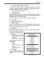
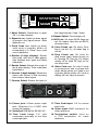
1. Reset Switch: Pushbutton to reset
SA-1 or clear displays
2. Signal In LED: Lights up when signal
is present. Any signal above -30db
lights this LED.
3. Good Code LED: Lights up when
valid code is present; blinks off
momentarily if a “Fatal” time code
error is detected.
4. Reader (8 digit display): Reads
time code, user bits or video phase;
also displays error types and faulty
addresses.
5. Reader Select: Selects the mode of
the 8 digit display: Time code/User
bits/Video ø.
6. Counter (4 digit display): Reads the
frame rate (fr/sec) of the incoming
time code or video signal.
Code
BEEPER
Video
Off
Drop Fr.
Video Code
On
the 4 digit counter: Code / Video.
8. Beeper Switch: Turns beeper off.
9. ASCII LED: On when ASCII flags are
set. On means User bits are ASCII;
off means Hex.
10. Color Frame LED: On when Color
flag is set (bit 11); off when flag is
not set.
12. Drop Frame LED: On solid for
drop frame code; blinks mostly on
for missing DF flag (bit 10); blinks
mostly off for false DF flag; off for
non drop code.
13. Video Code LED: On solid if code
is synchronous and in phase with
video; blinks mostly on if code is out
of phase; blinks mostly off if code is
drifting; off if no video is present.
7. Counter Select: Selects the input of
POWER
RS-232
12VDC
@ 300ma
TIME CODE
LOOP
VIDEO IN
INPUT
Off
75
Pin 2: TxD (Signal out)
Pin 3: RxD (Signal in)
Pin 5: SG (Ground)
14. Power jack: 2.5mm power input
jack. Requires 6 to 12VDC with
center pin positive.
17. Time Code Input: 1/4” for source
time code.
15. Serial port: DB-9M for RS-232 I/O.
18. Video Input: BNC connector for
video reference.
16. Time Code Loop: 1/4” jack
connected internally to the time
code input jack.
19. Termination switch: turns on
a 75Ω termination for video
reference.
Page 1
Introduction
The SA-1 is a powerful hand held analyzer designed to quickly and
accurately identify time code problems. The SA-1 identifies the type,
stability and frame rate of the incoming code; it verifies its proper synchronization (phase) with video; and it reports time code errors (i.e.
drop outs...)
It is the same analyzer as the one found in the Brainstorm SR-15+
Distripalyzer so it should be easy for SR-15+ users to operate the SA-1.
Table of contents
• Section 1: Setting up the SA-1
Connections ........................................................................... 2
Wiring ................................................................................... 2
• Section 2: Using the SA-1
Time Code Format and Frame Rate ........................................... 4
Frame Rate vs. Format / 29.97 vs. Drop Frame ................ 5
Proper bit width .............................................................. 6
Time Code / Video Phase ....................................................... 7
What does it mean for code to be in phase with video? ..... 7
How can you check video phase? ..................................... 7
Reporting Time Code Errors ..................................................... 8
Front panel error messages ............................................... 9
What is the difference between Reset and Clear? ............. 10
How do you reset or clear the SA-1? ............................... 10
Transmitting A Time Code Report ............................................ 11
Using a printer with the SA-1 .......................................... 11
Using a computer with the SA-1 ...................................... 12
Time Code Report .......................................................... 13
• Section 3: Application notes ......................................................... 14
• Appendix
A: Time Code Error Messages ................................................ 16
B: More on the Frame Rate Counter ........................................ 17
C: More on the video phase display ....................................... 18
D: Longitudinal Bit Assignment (SMPTE & EBU) ........................ 18
• Specifications ............................................................................... 20
Page 2
Section 1: Setting up the SA-1
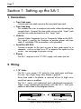
1. Connections
➫ Time Code input
Connect your time code source to the rear panel input jack.
➫ Time Code loop
This enables the user to analyze time code without breaking the
normal chain. Connect the time code source to the “Input” jack
and the time code destination to the “Loop” jack.
➫ Video In
Connect Video Composite Sync or Composite Video to this BNC.
This signal is used by the Analyzer to monitor phase with time
code. A switchable 75Ω termination is also provided.
➫ Serial Port (RS-232)
Connect a printer to this port to print a time code report or a
computer such as a Mac or a PC to capture the report on the
screen - see next page for proper wiring.
➫ Power
The SA-1 requires a 6 to 12 VDC supply with center pin hot.
2. Wiring
➫ 1/4” Jacks:
The SA-1 uses stereo 1/4” jacks for time code input and loop.
Pins are: Tip = high, Ring = low, Sleeve = ground.
Since time code is bi-phase, a reversal of low & high wires
would not cause a problem.
The SA-1 works with balanced and unbalanced equipment.
When using unbalanced equipment with the SA-1, wire your
cables as described in the diagrams below.
TIP
TIP
RING
SLEEVE
RING
SLEEVE
SA-1 Input
n.c.
SA-1 Loop (out)
Figure 1. Proper unbalanced wiring diagrams
Page 3
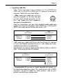
➫ Serial Port (DB-9M)
Only 3 pins are used on this connector: Pin 2 is RS-232 out
(TXD); pin 3 is RS-232 in (RXD); pin 5 is ground. To connect a
computer, follow the instructions below:
• Mac: make up a cable with an 8 pin
mini Din connector on the Mac side and
a 9 pin sub-D female connector on the
SA-1 side. Solder the 3 pins needed as
described in the table below.
6
3
7 8
4 5
1 2
8 pin Mini Din
Note: For convenience, you can use a standard modem cable and
replace one of the Din connectors with a DB-9F. Pins 4 (SG) and 8
(RXD+) are usually tied on the Mac side which is OK.
Signal Out
Signal In
Ground
SA-1
9 pin Sub-D
Mac
8 pin Mini Din
2 (TxD)
3 (RxD)
5 (SG)
5 (RxD)
3 (TxD))
4 (SG)
• PC: make up a cable with 25 pin sub-D on the the PC side and
a 9 pin sub-D female connector on the A-1 side. Solder the 3 pins
needed as described in the table below.
IMPORTANT: ON THE PC SIDE (25 PIN SUB-D), PINS 6 AND 20
(DSR - DTR) MUST BE TIED TOGETHER.
SA-1
9 pin Sub-D
Signal Out
Signal In
Ground
2 (TxD)
3 (RxD)
5 (SG)
PC
25 pin sub-D
3 (RxD)
2 (TxD)
7 (SG)
6 (DSR)
20 (DTR)
• Serial printer: To connect an Apple ImageWriter printer, use
the above described Mac cable. For serial printer with a DB25
connector, use the PC cable. For other printers, refer to your
printer’s manual for pin configuration.
Page 4
Section 2: Using the SA-1
A. Time Code Format & Frame Rate
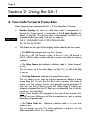
When playing time code into the SA-1, it first identifies its format:
➫
Reader Display: As soon as valid time code is recognized, its
format (or frame count) is indicated in the 8 digit display for
about 2 seconds. The display then automatically switches to its
selected mode (time code, user bits or video ø).
THE 3 STANDARD TIME CODE FORMATS ARE:
24, 25 OR 30 FR/SEC.
➫
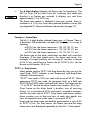
The 4 LED’s on the right of the display further identify the time code:
• The ASCII LED indicates the user bits’ format.
If the LED is off, UB format is Hex; if the LED is on, UB format is
ASCII. ASCII is often used to identify a scene, reel, date or camera
number .
• The Color Frame
or not.
LED
indicates whether code is “color framed”
This LED comes on if the color flag is set (bit 11); it is off if the flag
is not set.
• The Drop Frame LED indicates the drop-frame status.
This LED comes on as soon as the microprocessor detects a drop
frame flag (bit 10 set). But the SA-1 also monitors the code to
make sure the proper frames are actually being dropped. If
they are not, the LED blinks mostly off (false flag). If frames are
properly dropped but the DF flag was not detected, the LED blinks
mostly on (missing flag).
Note: Since frames are dropped at the end of the minutes, this
LED will not start blinking until the microprocessor sees a minute
boundary of good code.
• The Video Code
video or not.
LED
: Indicates whether code is in sync with
This LED comes on only if a video reference is present. For the
different modes of this LED, see page 7.
Page 5
➫
Fr/Sec
Hz
The 4 digit display indicates the frame rate (or frequency). The
SR-15+ strips the bit clock from the incoming time code and
displays it as frames per seconds. It displays any rate from
approximately 21 to 39 fr/sec.
The frame rate counter is updated 4 times per second. Since its
resolution is ± .01 fr/sec, it can show potential problems such as jitter
(see Appendix B “More on the frame rate counter”on page 17).
Format vs. Frame Rate
The SA-1’s 4 digit display indicates frame rate, NOT format. There is
a distinction. The format does not deal with frequency. It is a way of
counting:
at 30 fr/sec, the frame sequence is: 28, 29, 00, 01, etc...
at 25 fr/sec, the frame sequence is: 23, 24, 00, 01, etc...
at 24 fr/sec, the frame sequence is: 22, 23, 00, 01, etc...
The frame rate on the other hand does not deal with count but
frequency. If the tape speed varies, the frame rate varies. For
example, if a tape machine was running 5% too fast, a format
of 24 fr/sec would have a frame rate of 25.20 fr/sec. Yet the
format would remain 24 fr/sec.
29.97 vs. Drop Frame
Many people confuse 29.97 with drop-frame but they are not the
same thing: 29.97 indicates a rate (frequency) and drop-frame
indicates a format (count).
“29.97” time code is 30 fr/sec code with a rate of 29.97. When
generating 29.97 time code, the generator locks to a field rate
of 59.94 Hz (NTSC color rate) and pulls down the frame rate by
.1% to 29.97. But the format or frame count remains 30 fr/sec.
Drop Frame on the other hand is another way of counting
frames. It is a variation of 30 fr/sec format, invented to compensate for the color rate of 29.97. Drop frame code leaves certain
frame numbers out so that one hour of code time equals one
hour of stopwatch time when code is running at 29.97.
Drop and non-drop code can both be generated at a rate of 30
or 29.97 fr/sec. For that reason, the frame rate and the drop
frame status are displayed separately on the SA-1’s front panel.
Page 6
Proper bit width
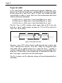
In LTC, each word is divided into 80 equal segments called bits, numbered 0 to 79 (for bit assignment, see appendix D on page 18). Each
bit can either be a “one” or a “zero”: a “one” has a level shift halfway though its width; a “zero” does not. The time between each level
shift can easily be calculated:
At 30 fr/sec it is 417µs for a “zero”and 208µs for a “one”,
At 25 fr/sec it is 500µs for a “zero”and 250µs for a “one”,
At 24 fr/sec it is 521µs for a “zero”and 260µs for a “one”.
The SA-1 has a ±25% window which means that at 30 fr/sec, the
level of a “zero” could remain constant for 313 to 521µs and of a
“one” for 156 to 260µs.
417µs
417µs
208µs
“Zero”
“One”
Figure 2. Bit width at 30 fr/sec.
However, some VCR’s distort the bit width beyond that window (the
“one’s” become too narrow). If the SA-1 does not recognize valid
time code with a signal present at its input for over 1 second, it
switches automatically to an alternate setting to accommodate these
distortions. If time code is then recognized, a “alternate bit width window” message is reported in the time code report.
The SA-1 remains on this alternate setting until reset (automatically or
manually).
Page 7
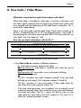
B. Time Code / Video Phase
What does it mean for time code to be in phase with video?
When time code is recorded on video tape, it must be synchronous with
the video signal, meaning that the beginning of each time code word
must coincide with the beginning of the video frame it describes. This is
essential for video editing.
There is one time code word for each frame. Each word is made up of
80 bits, numbered from 00 to 79 (see diagram below). Time code is
phased properly with video when the end of bit 79 of time code lines up
with field 1 line 5 of video (± 1 line).
How can you check video phase with the SA-1?
ONE TIME CODE FRAME (12:35:08:28)
Sync Word
64
68
72
76
Sync Word
0
F1L5
4
8
12
16
20
24
Video Field 1
28
32
36
40
44
48
F2L5
52
56
60
64
Video Field 2
68
72
76
0
4
F1L5
ONE VIDEO FRAME
Figure 3. Proper alignment of time code and video
➫ The Video Code LED indicates 4 different conditions:
on: time code is properly phased with video;
blinking mostly on: time code is resolved with video but out of
phase;
blinking mostly off : time code is non-synchronous (drifting);
off : no video is present.
The SA-1 considers time code “properly phased” if the time code
bit lined up with video F1L5 is between numbers 75 and 04.
The SA-1 considers it “non-synchronous” if time code moves by
more than 2 bits with respect to video F1L5.
If the time code generator was mistakenly set to internal crystal
instead of external video, there would be a very slow drift between
time code and video. The SA-1 reports this drift as soon as time
code moves by more than 2 bits with respect to F1L5, even if it is
within the “properly phased” window.
Page 8
➫ On the reader display you can monitor the sync between time code
and video:
With its selector switch in the “video ø” position, the reader shows
which bit of the time code word lines up with video Field 1 Line 5
(“V” drive).
With synchronous code, the display should read: “bit 79”. In the
real world however, things are different and phase will often be
slightly off. For example, if the display reads “bit 68” or “bit 07”,
the address track was possibly misaligned on the VCR and your
synchronizer may show some slight sub-frame offset (i.e. 03,12,
etc) when locked to code like this. So long as you are within a few
bits of 79 and the bit number stays the same, you should have no
problems.
Note: If “V” drive is at the edge of a time code bit, 2 bit numbers
(those on either sides of that edge) will flicker in the display.
WARNING: IF THE BIT NUMBER DRIFTS, TIME CODE IS
ASYNCHRONOUS AND MAY BE USELESS FOR YOUR
APPLICATION.
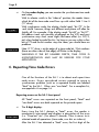
C. Reporting Time Code Errors
One of the functions of the SA-1 is to detect and report time
code errors. Errors considered serious enough to cause a
synchronizer problem (such as a repeated frame) are labeled
“fatal” by the SA-1. Others are “non-fatal”. For a complete list,
see appendix A on page 16.
Reporting errors on the SA-1 front panel
All “fatal” errors are reported on the front panel; “fatal” and
“non fatal” errors are both reported on the printed report.
➫
The 8 digit display:
Every time the SA-1 detects a “fatal” error, the reader is
momentarily interrupted and displays a description of the error
(i.e. “Drop-out” etc...) for about 2 seconds. Then it returns to its
selected mode of operations (time code, user bits or video ø).
After the SA-1 has detected a “fatal” error, the first digit of the
Page 9
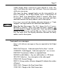
reader display blinks continuously (until cleared or reset). This
way, if you leave the room, you will know if an error occurred
while you were away.
After tape has been stopped (code must be interrupted for at
least 5 seconds), the 8 digit display shows a description of
the first “fatal” error detected for about 2 seconds. After these
2 seconds, it indicates where the error occurred and then
alternates between the faulty address and its description.
If no error occurred, the display alternates between a “Code
Stopped” message and the last valid time code address.
View the first five errors: The SA-1 keeps the first 5 errors
detected in memory. After time code has been stopped, tap
the reset button to toggle through them. Each tap advances the
display to the next error until the fifth one. Then it returns to the
first. For each error, the display alternates between the faulty
address and its description.
Front panel error messages:
Here is a list of error messages as they are reported on the 8 digit
display:
DROP OUT: Drop out - Code interruption for less than 1 second.
CODESTOP: Code Stopped - Code interruption for 1 sec. or more.
DISCONT: Discontinuous Address or repeated frame
INVALID: Invalid Address - Any non valid number i.e. 39 frames.
VID-LOST: Video Loss - Any interruption in the video signal.
FORM CHG: Format Change
DROP X: Wrong number of frames dropped (X indicates the number
of frames)
DROP CHG: Change in the Drop Frame Status
COLR CHG: Change in the Color Frame status
Page 10
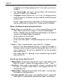
In addition to the 8 digit display, the SA-1 also alerts you of errors
as follows:
➫ The “Good Code” LED (input section) blinks off momentarily
whenever a “fatal” error is detected.
➫ The Beeper sounds whenever the “GOOD CODE” LED changes from on
to off. If necessary, the beeper can be turned off via the front panel
on/off switch.
The SA-1 keeps track of errors and statuses on the front panel and it
may be useful at times to reset the SA-1 or clear some of its displays.
What is the difference between Reset and Clear?
• Reset: When you reset the SA-1, it is as if you were playing new time
code. After a reset, the SA-1 begins its normal sequence again:
- the SA-1 identifies the time code format and displays it for about 2
seconds in the 8 digit display (see page 4);
- the front panel LED’s are all reset;
- the “first 5 errors” register is erased;
- a new time code report is initiated (through the serial & parallel
ports).
• Clear: A “Clear” command clears some of the SA-1’s displays:
- If an error has been detected and the 1st digit of the reader is
blinking, a clear command stops the blinking and clears the “first 5
errors” register (i.e. the next error detected will now be considered
to be the first error).
- If the video code LED is blinking, a clear command stops the blink
and resets the LED.
How do you reset or clear the SA-1?
• Manual Reset: To manually reset the SA-1, press and hold the reset
button for at least 1 second. The 8 digit display will say: “- reset -”
• Auto Reset: When code is interrupted for at least 5 seconds an end
of report is initiated. When code is reintroduced, the SA-1 is
automatically reset.
• Manual Clear: Tapping the reset button while code is running clears
the displays as described above.
• Auto Clear (partial): When code is interrupted for at least 1 second, the
video code LED is automatically cleared when code is reintroduced.
Page 11
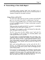
D. Transmitting a Time Code Report
A complete report including “fatal” and “non-fatal” errors as
well as format information can be sent to an external printer or
computer through the rear panel serial port.
Using a Printer with the SA-1
To send a time code report to a printer, connect it to the RS-232
port, turn it on and set it so that it is ready to print (“on line”).
If you are using a parallel printer, you need to connectit through
a serial to parallel converter. If using a serial printer, connect it
directly to the SA-1
When you play time code into the SA-1, a report is immediately
initiated (see time code report on page 12).
The header is first printed, as well as the format, the video reference information and the start time.
The SA-1 then prints the title “address errors” and waits for
errors to happen. As soon as they occur, the faulty address and
a description of the error is printed.
An end of report is printed automatically when time code is interrupted for at least 5 seconds. This includes a summary and the end
time. In the summary, the SA-1 reports general comments such as
Time Code properly synced with Video (or not) and non standard
formats such as Color Framed Code not synced with Video or 25
Drop code etc...
Both serial and parallel printers can be used with the SA-1.
However, you should use the kind of printer that prints one line
at a time such as dot matrix printers and not full page printers
such as laser printers.
If you want to use a laser printer, you should first send the report
to a computer, as described below, then send the report from the
computer to the laser printer. This would also allow you to customize the report, if needed, by adding information such as the
date, the name of the studio, the name the client, etc...
Page 12
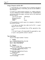
Using a Computer with the SA-1
1. Connect the SA-1 to a serial port of your computer (see page 2
for wiring information). On the Mac, you can use the Modem or
the Printer port.
2. Launch any communication program (i.e. modem program),
set your computer for direct connection (not through phone
connection), select the proper serial port and set the speed and
format as follows:
Transmission speed:
Bits per character:
Stop bits:
Parity:
9600 baud
8
1
None
3. The procedure to send a report to a computer is identical to
the one for a printer:
• As soon as you play time code into the SA-1, a report
appears on the screen
• If any errors are detected, they will be reported as they
occur.
• An end of report will automatically be generated as soon
as input is interrupted for at least 5 seconds.
Time Code Report
The time code report includes 7 sections:
1.
Header
Line 1: BRAINSTORM SR15+ VER #.##
Line 2: TIME CODE DISTRIPALYZER
Line 3: TIME CODE REPORT
2. Format:
Frame count & drop status :
24, 25, 30 Drop Frame or 30Non Drop
Color bit status: reported only if active :
Color Bit active
Parity bit status: reported only if active:
Parity bit active
User Bits format:
User Bits: HEX or ASCII
User Bits message:
Page 13
first UB message detected is printed
NOTE: If SA-1 had to switch to the alternate setting to read time
code (see “Proper bit width” on page 6), the following message is
printed just above the “Format” heading:
Alternate bit width window
3. Video Reference
If video is present, the SA-1 reports which bit of time code is lined
up with “V” drive (video field 1 line 5) 3 seconds after time code is
detected (to allow for ramp up time);
if video is not present, the SA-1 reports: Video not present.
4. Start Time
First valid Time Code address.
5. Address Errors
The SA-1 prints the title “ADDRESS ERRORS”, then waits for
errors to occur. As soon as an error is detected, the faulty address
and the error description are transmitted.
6. Summary
When input is interrupted for 5 seconds, an end of report is printed which includes the following:
Video Sync (if video reference
was present):
code properly synced
code resolved but out
of phase
code non synchronous
Non-standard formats (if
applicable):
24DF
25 DF
non synchronous color
code
Undefined bit set
7. End Time
The last valid address is
printed at the very end of the
report.
BRAINSTORM SR-15+ Ver 3.05
Time Code Distripalyzer
TIME CODE REPORT
Alternate Bit Width Window
*** FORMAT ***
30 Drop Frame
Color Bit active
User bits: HEX
01234567
*** VIDEO REFERENCE ***
Present
“V” drive at bit 79
*** START TIME ***
01.00.00.00
*** ADDRESS ERRORS ***
01.12.36.05
01.18.41.23
01.18.41.27
01.23.45.07
Drop out
Bad bits: 28
Frame repeated
Code stopped
*** SUMMARY ***
VIDEO SYNC: Code Properly Synced
*** END TIME ***
01.23.45.07
END OF REPORT
Time Code Report
Page 14
Section 3: Application notes
As a general rule, it is always better to know about time code problems early rather than late in a project. More options are available
early on to fix the problem and if it cannot be fixed and you have to
start over, at least less time has been wasted.
Here are some specific suggestions regarding the use of the SA-1:
1. When striping a tape, run time code through the SA-1
Don’t take your time code generator for granted. Maybe you
didn’t set it properly, maybe one of the LED’s is broken, maybe
the instructions are not clear, maybe it is broken. There are plenty
of good reasons why your generator could generate something
different than what you wanted.
Patch the output of your time code generator into the SA-1 and the
SA-1’s loop into your tape machine. Through the SA-1 you can
monitor your generator. At this stage, if there are any errors, you
only have to re-stripe correctly to fix the problem. It could be a lot
worse if discovered later...
You can even print a report during recording by analyzing the
recorded time code off the playback head. The report will show any
problem with the generator or with the recording.
2. Print a time code report from pre-striped tapes
When working with a pre-striped tape, you should run this time
code through the SA-1 and print a complete report as soon as
possible, preferably before you even start the session. See if the
format is correct, check the video phase and make sure there are no
drop outs or any other type of errors.
If a client brings a tape with faulty time code to your studio, he will
usually blame your equipment for the sync problems and it can be
very frustrating. The time code report ends any argument before it is
even started.
If you are a composer and you receive a work copy from a transfer
house, you can save a lot of aggravations by finding out about nonsynchronous time code before you record any music.
Page 15
If you do not have time to run the tape through the analyzer before
the start of the session, make sure that the time code is running
through the SA-1 during the session.
4. Align your VCR’s address track
You can align the address track on your VCR by connecting the
address track time code and the video signal into your SA-1.
Select “video ø” on the reader selector switch and move the address
track head until you read“ bit 00”; then move it back a little and stop
as soon as you read “bit 79”. This way, the trailing edge of bit 79
will be aligned with F1L5 (see figure 4 on page 18).
WHAT TO DO ONCE YOU DISCOVERED A PROBLEM?
There are many different types of problems that can occur with time
code. Many times, the solution will depend of how early in the project it was discovered. Following are some very general suggestions
Problems
Solutions
Time code is synchronous but
out of phase with video
Use a delay line to delay time
code until the phase display
reads “bit 79”
Time code is non synchronous
with video
Generate new time code
referenced to video
There is a hole in the time
code track (i.e. accidental
punch in)
Use a time code generator set
to jam-sync and regenerate
new code
Repeated frame or missing
frame
Regenerate new time code
The wrong time code format
was recorded
Regenerate new code with a
generator that can do format
conversions
NOTE: Many of the problems listed above can be solved with the
Brainstorm SR-3 Time Code Repair Kit. For more information, call
your Brainstorm Electronics dealer.
Page 16
Appendix A: Time Code Error Messages:
“Fatal” errors are the ones considered serious enough to cause
a synchronization problem. All “fatal” errors are reported on the
front panel and activate the buzzer and the relay; “fatal” and “non
fatal”, both appear on the report, with their corresponding time code
address.
FATAL ERRORS:
(fatal errors are reported on the front panel as shown in parentheses)
Drop out (“DROP OUT”):
Interruption of time code for less than 1 second. Level has to fall
below input threshold of -30dB.
Code Stopped (“CODESTOP”):
Interruption of time code for more than 1 sec.
Repeated Frame (“DISCONT”):
Same frame address detected twice consecutively.
Discontinuous address (“DISCONT”):
Any non continuous address (either ascending or descending)
Invalid Address (“INVALID”):
Any non valid number such as 39 frames or 75 minutes.
Video Loss (“VID-LOST”):
Any interruption in the video signal.
Format Change (“FORM CHG”):
Change in the time code count.
Wrong number of frames dropped (“DROP X”):
Reports errors in Drop Frame format. Indicates how many frames
were dropped.
Change in DF status (“DROP CHG”)
Reported if DF flag changes.
Change in Color status (“COLR CHG”)
Reported if Color flag changes.
NON FATAL ERRORS:
(some of these messages are not errors but just changes)
Bad Bit: XX
Any bit wider or narrower than ± 25% of time code specifications.
XX indicates the number of bad bits for that frame.
Bad Sync Word
Reported if no Sync Word was detected after 256 bits.
Page 17
Code not in Sync with Video
If time code slips by more than 2 bits with respect to video“V”drive.
Undefined Bit Set
Reported if one of the undefined bits is set (SMPTE: bit 58 / EBU: bits 10 &
58).
Alternate bit width window
Reported if the SR-15+ had to go to this setting in order to read time code
(see pg 6).
Change in User status
Reported if UB flag changes.
User Bit Change
If User Bits messages change, the first 30 different messages are
reported. After that, the SA-1 disregards any change until reset.
External trigger in
Reported with its coinciding time code address, when tip and sleeve
of the 1/4” input jack are shorted.
Code Restarted
Follows a “Code Stopped” message. Indicates where time code reappeared.
Video Restarted
Follows a “Video Loss” message. Indicates where Video reappeared.
Still Frame:
Reported if the same address is detected consecutively, 3 times or
more.
Appendix B: More on the Frame Rate Counter...
Since the least significant digit’s (LSD) resolution is ± .01 frames per second
(.033%), any wow, flutter or speed variation of your time code source is
easily detected.
a. Time code generators generally display a very steady frame rate
with no fluctuation, whether on internal crystal, external video or tone
reference. A ± one LSD fluctuation probably would not cause any
problems.
b. Analog tape machines have typical wow/ flutter speed specifications of ± .03% to ± .1% (or more). Therefore a fluctuation of 2 (or
even 3) LSD is normal. Machines like the Sony APR-24 or Otari MTR90 are quite stable and may only move 1 LSD every 5 to 10 sec.
c. 3/4” VCR’s have wow/ flutter specs up to .3%. They can therefore
fluctuate almost .1 frame; the address track is usually more stable
than the 2 audio tracks. However a machine in good condition
usually fluctuates less than ± .1 frames.
Page 18
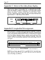
Appendix C: More on the video phase display...
When the SA-1 detects F1L5 (actually F1L4 1⁄2 as detected by the LM1881
video sync detector), it looks at which bit is in the time code working
register. The number of that bit is displayed in the video phase window.
However, the highest resolution of time code is one bit which is about
417 µsec. while a video line is about 63 µsec. This means that there are
approximately 6 1⁄2 video lines per time code bit.
1
VIDEO
2
3
4
5
6
7
8
9
10
Field 1 Line 5
CODE
Bit 0
Bit 79
Figure 4. Proper alignment of video and time code
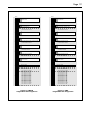
Appendix D: Longitudinal bit assignment:.
Each word of LTC is divided into 80 equal segments called bits, numbered
0 to 79. These bits are mainly grouped by four into Binary Coded Decimal
words to form decimal numbers (0 to 9). Twenty six of these bits are assigned
to the Time Address information (frames, seconds, minutes and hours); thirty
two are assigned to the Binary Group information (user bits); sixteen are
used for sync (sync word) and the remaining six are used for flags or are still
unassigned.
Sync
Word
64
68
72
Frame
Units
76
0
User
Bits
4
Frame
Tens
8
User
Bits
12
User
Bits
Second
Units
16
20
Second
Tens
24
User
Bits
28
Minute
Units
32
User
Bits
36
Minute
Tens
40
User
Bits
44
Hour
Units
48
User
Bits
52
Hour
Tens
56
User
Bits
60
Sync
Word
64
68
72
Frame
Units
76
0
User
Bits
4
Frame
Tens
8
ONE SMPTE FRAME
Figure 5. SMPTE Word
Address: 05:38:14:29 - User Bits: 00000000 - drop & color flags set
SMPTE has a frame rate of 30 fr/s and EBU 25 fr/s but both time
codes have the same 80 bits per word. Most bits are the same but
some of the flags are different.
12
Page 19
Bit No.
0
1
2
3
4
5
6
7
8
9
10
11
12
13
14
15
16
17
18
19
20
21
22
23
24
25
26
27
28
29
30
31
32
33
34
35
36
37
38
39
40
41
42
43
44
45
46
47
48
49
50
51
52
53
54
55
56
57
58
59
60
61
62
63
64
65
66
67
68
69
70
71
72
73
74
75
76
77
78
79
Bit No.
1
2
4
8
FRAME UNITS
FIRST BINARY GROUP
10
20
FRAME TENS
DROP FRAME FLAG
COLOR FRAME FLAG
SECOND BINARY GROUP
1
2
4
8
SECONDS UNITS
THIRD BINARY GROUP
10
20
40
SECONDS TENS
BI-PHASE MARK PHASE CORRECTION BIT
FOURTH BINARY GROUP
1
2
4
8
MINUTES UNITS
FITH BINARY GROUP
10
20
40
MINUTES TENS
BINARY GROUP FLAG BIT
SIXTH BINARY GROUP
1
2
4
8
HOURS UNITS
SEVENTH BINARY GROUP
10
20
HOURS TENS
UNASSIGNED ADDRESS BIT 58
BINARY GROUP FLAG BIT
EIGHTH BINARY GROUP
SYNC WORD - BIT “ZERO”
SYNC WORD - BIT “ONE”
SYNC WORD - BIT “ZERO”
SYNC WORD - BIT “ONE”
Figure 6. SMPTE
longitudinal bit assignment
0
1
2
3
4
5
6
7
8
9
10
11
12
13
14
15
16
17
18
19
20
21
22
23
24
25
26
27
28
29
30
31
32
33
34
35
36
37
38
39
40
41
42
43
44
45
46
47
48
49
50
51
52
53
54
55
56
57
58
59
60
61
62
63
64
65
66
67
68
69
70
71
72
73
74
75
76
77
78
79
1
2
4
8
FRAME UNITS
FIRST BINARY GROUP
10
20
FRAME TENS
UNASSIGNED ADDRESS BIT 10
COLOR FRAME FLAG
SECOND BINARY GROUP
1
2
4
8
SECONDS UNITS
THIRD BINARY GROUP
10
20
40
SECONDS TENS
BINARY GROUP FLAG BIT
FOURTH BINARY GROUP
1
2
4
8
MINUTES UNITS
FITH BINARY GROUP
10
20
40
MINUTES TENS
BINARY GROUP FLAG BIT
SIXTH BINARY GROUP
1
2
4
8
HOURS UNITS
SEVENTH BINARY GROUP
10
20
HOURS TENS
UNASSIGNED ADDRESS BIT 58
BI-PHASE MARK PHASE CORRECTION BIT
EIGHTH BINARY GROUP
SYNC WORD - BIT “ZERO”
SYNC WORD - BIT “ONE”
SYNC WORD - BIT “ZERO”
SYNC WORD - BIT “ONE”
Figure 7. EBU
longitudinal bit assignment
Page 20
Specifications
Time Code Reader:
8 digit display - character height: .12”
Speed range: reads at play speed only (± 25%)
Frame Rate Counter:
4 digit display - character height: .12”
Reading range: ≈ 21 to 39 fr/sec
Display accuracy: ± 20 ppm plus ± 1⁄2 the least significant digit
Resolution: .01 Fr/sec
Update rate: 4x per sec.
Connectors:
1/4” Jack (2): time code in & loop
BNC: Video In
DB-9M: Serial port
2.5mm jack: Power inlet (center pin hot)
Termination switch: 75Ω to ground - for Video In
Power: 6 - 9 VDC
Dimensions: 5” x 1 1⁄2” x 5 1⁄4”
Page 21
Other Brainstorm Products
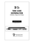
SR-15+ Time Code Distripalyzer
Combines 3 units in a single space 19” chassis: a time code analyzer,
a 1x5 Time code distributor (w/reshaping on all 5 outputs) and a pilot
tone stripper. The analyzer identifies time code format, detects errors and
monitors video sync and color field alignment. A comprehensive report can
be sent to a printer or computer via the parallel and RS-232 ports.
SA-1 Time Code Analyzer
Same analyzer as the one found in the SR-15+, in a small portable package (same as the SR-3). It operates on an external 6VDC supply and can
be used with a battery pack.
SR-26 Dual Time Code Distributor / Reshaper
Cleans up time code and distributes it through 6 individually buffered outputs. Can be used as 2 separate units: 1x4 (master) + 1x2 (slave) or as a
single 1x6 unit - Same reshaping circuitry as the SR-1 with individual output level controls & switchable output rise times.
SR-1 Time Code Reshaper
Cleans up unreadable code by eliminating distortions and level fluctuations.
Low input threshold (better than -30db) - Reshapes in fast forward and
rewind modes - Balanced or unbalanced input and output - Adjustable
output level - Switchable output rise time (SMPTE/EBU/square wave).
SR-2 Frame rate counter
Same unit as the SR-1 with a 4 digit counter that reads the incoming time
code’s frame rate. Ideal to identify the code’s format and verify it’s stability Very accurate counter (4 updates per second) also shows potential problems
such as wow and flutter or jitter.
TB-4 Communicator System (wireless talkback remote)
A high-performance infrared remote that allows the producer to activate the
console’s talkback from anywhere in the control room - 4 switchable talkback functions - Rechargeable transmitter - No aiming necessary - Easy
to install - Includes transmitter and receiver.
For more information on these products, contact your Brainstorm Electronics dealer.
BRAINSTORM ELECTRONICS, INC.
www.brainstormtime.com
Distributed Exclusively by:
plus24
West Hollywood, CA - USA
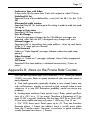
Tel: (323) 845-1155 • Fax: (323) 845-1170