1
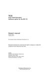
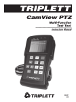
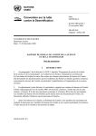
VSG-4
Video Sync
Generator
For the Brainstorm DCD-8
Operations Manual
Software version 2.00
BRAINSTORM
ELECTRONICS, INC.
...Intelligent Solutions For The Recording Studio
VSG-4
Video Sync Generator for the DCD-8
Operations manual
Version 2.00
June 2007
All materials herein © Brainstorm Electronics, Inc.
Brainstorm Electronics reserves the right to change or modify the contents
of this manual at any time.
Credits
Concept: AID, Brainstorm Electronics
Software: Gerry Lester
Manual: Bernard Frings, Gerry Lester
Technical Assistance: Jeff Evans, Jim Pace
Brainstorm Electronics, Inc.
5100 Goldleaf Circle, 215 - Los Angeles, CA 90056 - USA - Tel: +1/323/845-1171
www.brainstormtime.com
Page 2
VSG-4 Operations Manual
Table of contents
1. INTRODUCTION . . . . . . . . . . . . . . . . . . . . . . . . . . . . . . . . . . . . . . . . . . . . . . . . . . . 2
2. INSTALLATION . . . . . . . . . . . . . . . . . . . . . . . . . . . . . . . . . . . . . . . . . . . . . . . . . . . . 2
3. CONNECTING THE VSG-4 . . . . . . . . . . . . . . . . . . . . . . . . . . . . . . . . . . . . . . . . . . . 3
4. MENUS DESCRIPTION . . . . . . . . . . . . . . . . . . . . . . . . . . . . . . . . . . . . . . . . . . . . . . 4
51- Video Option . . . . . . . . . . . . . . . . . . . . . . . . . . . . . . . . . . . . . . . . . . . . . . 4
52- Video Out Ref . . . . . . . . . . . . . . . . . . . . . . . . . . . . . . . . . . . . . . . . . . . . 4
53- HD Out . . . . . . . . . . . . . . . . . . . . . . . . . . . . . . . . . . . . . . . . . . . . . . . . . 5
54- SD Out . . . . . . . . . . . . . . . . . . . . . . . . . . . . . . . . . . . . . . . . . . . . . . . . . . 5
5. NOTES ON GENLOCKING . . . . . . . . . . . . . . . . . . . . . . . . . . . . . . . . . . . . . . . . . . 6
6. FRONT PANEL LEDS . . . . . . . . . . . . . . . . . . . . . . . . . . . . . . . . . . . . . . . . . . . . . . . . 8
7. SPECIFICATIONS . . . . . . . . . . . . . . . . . . . . . . . . . . . . . . . . . . . . . . . . . . . . . . . . . . 8
1. Introduction
The VSG-4 generates analog tri-level and bi-level sync signals for HD and SD video applications. Up to 4 different sync formats can be generated simultaneously through it’s 4 BNC
outputs, 2 HD and 2 SD. The VSG-4 operates either as a master clock generator or genlocked to any of the references available to the DCD-8.
Designed as an option for the Brainstorm DCD-8 Word Clock Distripalyzer, the VSG-4,
combined with the DCD-8, delivers a complete solution for all sync requirements in the
post-production, recording and broadcast environments.
2. Installation
2.1. UNPACKING
When unpacking the VSG-4 the following items should be in the shipping carton:
•
•
•
•
VSG-4 board
(3) screws
(1) 34 pin interconnect cable
Owner’s Manual & Registration card
2.2. INSTALLING THE VSG-4
The VSG-4 is a 2” x 5.4” circuit board designed to be installed inside the DCD-8.
Installation should be performed carefully, using usual precautions.
1. Turn off DCD-8 by unplugging the power cord.
2. Remove the top panel screws and remove the top panel.
3. Inside the chassis, locate the area for the VSG-4: left of the mother board, behind
the front panel BNC
4. Remove the hole covers for the 4 BNC connectors on the rear panel
5. On the mother board side, unplug the ribbon cable connecting the front panel
BNC’s so it is out of the way
VSG-4 Operations Manual
Page 3
6. Feed the 4 BNC connectors on the VSG-4 into the 4 rear panel BNC holes and
slide the VSG-4 PCB on top of the 3 stand offs. You’ll need to angle the PCB appropriately to find its way into proper position.
7. Secure the PCB in place with the 3 screws provided.
8. Reconnect the front panel BNC’s into the mother board.
9. Connect the VSG-4 to the mother board using the 34 pin cable provided. This
cable needs to be folded twice as shown on the illustration below.
CAUTION: Be absolutely certain pin 1 is in the right place on both ends of
the cable before powering on. Failure to do so will cause damage to the unit.
Front Panel
BNC
FRONT
Pin 1
VSG-4
REAR
Mother board
2.3. POWER ON
Once the VSG-4 is installed properly, power on the DCD-8. The front panel LED’s
located on the far right under “VID SYNC GEN” should light up, indicating the current selection.
3. Connecting the VSG-4
The VSG-4 has 4 BNC output connectors. Two of those are for HD Sync, the other
two for SD . They are labeled as such on the rear panel (HD1, HD2, SD1, SD2).
Use standard 75Ω video cables on those outputs.
3.1. DAISY-CHAINING
SD: On the SD outputs, if absolutely necessary, it is acceptable to daisy chain multiple devices on a single connector. However, make sure that the last one in the chain,
and only the last one, has a 75Ω termination.
HD: On the HD outputs, do not daisy chain. Connect only 1 device per output and
make sure it is properly terminated (75Ω ).
Page 4
VSG-4 Operations Manual
4. Menus Description
4.1. MENU 51: VID OUT HD 1&2
The VSG-4 provides stable HD clock rates over long periods of time by making use
of the DCD-8’s B Domain PLL. Which means that, with HD enabled, the DCD-8 no
longer has access to Domain B for word clock.
With SD only enabled, the VSG-4 uses Domain A and both domains are available
for word clocks. However, Domain A cannot be VSO’d.
Therefore, the VSG-4 gives you 3 choices for the Video Outputs, in menu 51:
- Enable HD & SD
- Enable SD only
- Disable
Here is what happens under each circumstances:
ENABLE HD & SD:
- the HD and SD outputs are active
- Domain B is used by the VSG-4, and is thus unavailable for audio use
- the HD and SD outputs are referenced as selected in Menu 52
- Menu 21 (RATE B) will show “Using Rate A”
- Menu 22 (REF B) will be skipped
ENABLE SD ONLY:
- the HD output connectors are grounded
- the SD outputs are active and are referenced to REF A
- Menus 52 & 53 will be skipped
- Domains A & B are available for audio use
- Menu 2 (REF A) does not offer the VSO option.
DISABLE:
- the HD and SD output connectors are grounded
- Menus 52, 53 & 54 will be skipped
- No restrictions on the DCD-8: Domains A & B are available for word clocks
and can both be VSO’d.
4.2. MENU 52: VIDEO OUT REF
This menu is only available when HD & SD Video have been enabled in menu 51.
Menu 52 operates in the same way as the “REF B” menu, and sets up a separate
reference for all Video Outputs (HD and SD). When ‘Use REF A’ is selected, the
video and the audio share a common reference, the one selected in menu 02.
As with menu 22 (REF B), when necessary, the Video Reference can be different
than the REF A. Any of the available inputs can be selected. There are 2 choices for
VSG-4 Operations Manual
Page 5
the rate of the reference: SET or LEARN (for more information, see chapter 11 in the
DCD-8 manual).
CAUTION: When selecting a separate reference for the video output, i.e. different
than ‘Use REF A’, the audio and video outputs may not have the same reference.
4.3. MENU 53: HD OUT
Menu 53 sets the HD Video output formats and rates. Each of the 2 HD outputs are
set individually and can have a different format and rate.
Selections available are:
720p/23.976
720p/24
720p/25
720p/29.97
720p/30
720p/50
720p/59.94
720p/60
1080i/25
1080i/25 295M
1080i/29.97
1080i/30
1080sF/23.976
1080sF/24
1080sF/25
1080sF/29.97
1080sF/30
1080p/23.976
1080p/24
1080p/25
1080p/29.97
1080p/30
1080p/50
1080p/50 295M
1080p/59.94
1080p/60
p stands for ‘Progressive’; i stands for ‘Interlaced’; sF stands for Segmented Frame
295M stands for SMPTE standard 295M
4.4. MENU 54: SD OUT
Menu 54 sets the SD Video output formats and rates. Each of the 2 SD outputs are
set individually and can have a different format and rate.
Selections available are:
525i/29.97
525i/30
625i/23.976
625i/24
625i/25
NTSC
monochrome
slow PAL
slow PAL
PAL
Page 6
VSG-4 Operations Manual
5. Notes on genlocking
5.1 FORMS OF GENLOCK
There are three forms of genlock:
1. INTER-OUTPUT SYNC
Output formats are divided into two groups, pulldown and non-pulldown, and within each
group the relationship between the output frame edges is fixed.
In the non-pulldown group, frame edges for video rates of 30, 25, 24, 60 and 50 Hz
will all be coincident once per second (1Hz), and the 30, 24, 60 rates will be further
coincident at a 6Hz rate.
The pulldown group – 29.97, 23.976, 59.94 – is similarly synchronized.
2. SYNC TO VIDEO INPUT
When the Video Output Reference (Menu 52, and Menu 02 REF A if Menu 52 is set to
“Use REF A”) is set for “Video”, the Video Output waveforms will be tightly synchronized
to the Video Input waveform.
Note however that edge synchronization will not cross the pulldown/non-pulldown barrier – in other words, a non-pulldown output will not edge align with a pulldown input,
although its long term rate will be derived from that input.
3. SYNC TO WORDCLOCK ‘RATE A’ OUTPUT
When the Video Output Reference is set to anything other than “Video”, then the Video
Output waveforms will be correctly aligned with the DCD-8 “RATE A” Output waveforms
(i.e. wordclock rising edge coincident with video start of line 1) under the following circumstances:
(a) Non-pulldown video outputs will edge align to RATE A rates of 48000, 44100,
32000 and their multiples.
(b) Pulldown video outputs will edge align to RATE A rates of 48000, 47952, 44056
and their multiples.
(c) REF A (Menu 02) and the Video Output Reference (Menu 52) must be identically
set. This is most easily achieved by setting Menu 52 to “Use REF A”.
5.2 EDGE COINCIDENCE BETWEEN DIFFERENT FRAME RATES
The following illustration shows the relationship between 24, 25 and 30f/s.
1 Second
6 Hz
24 Fr
30 Fr
25 Fr
5 Hz
With 24 and 30 f/s, edge coincidence occurs 6 times per second (6 Hz); with 25 and 30, it
occurs 5 times per second (5Hz); with 24 and 25, it occurs 1 time per second (1 Hz).
A similar relationship exists for the pulldown rates (23 & 29) with a frequency of 5.994Hz.
VSG-4 Operations Manual
Page 7
5.3 EDGE ALIGNMENT (GENLOCK) COMBINATIONS
The following table indicates when input to output edge alignment will occur.
Note that all video outputs are rate locked at all times, even when not edge aligned.
Video Output Types and Rates
PAL
Ref Type
Slow PAL
24
NTSC
Slow PAL
23.976
HD 30
HD 25
HD 24
HD 29.97
HD 23.976
30.000
25.000
24.000
29.970
23.976
Y
(5Hz)
(6Hz)
Y
(5.994Hz)
25.000
(5Hz)
Y
(1Hz)
24.000
(6Hz)
(1Hz)
Y
(5.994Hz)
Y
Y
(11.988Hz)
Y
(11.988Hz)
Y
Y
(5.994Hz)
Y
Ref Rate
30.000
29.970
DCD-8
Video
Input
23.976
60.000
Y
(5Hz)
(12Hz)
59.940
50.000
(10Hz)
Y
(2Hz)
32000.000
(10Hz)
Y
(8Hz)
42293.706
42336.000
44055.944
44100.000
Y
Y
(12Hz)
44144.100
DCD-8
RATE ‘A’
Wordclock
Output
45937.500
45983.438
46033.966
46080.000
47952.048
48000.000
Y
Y
Y
48048.000
50000.000
50050.000
Hz values for edge coincidence are given where not every video output frame edge aligns to
a corresponding reference edge.
5.4 COLOR FRAMING
The DCD-8 video path does not support color framing, so when for example an NTSC
Video Output is genlocked to an NTSC Video Input the color framing sequence will not
necessarily be reproduced. The same applies to PAL.
When the SD Video Reference is set to match the video output(s) - NTSC to NTSC, PAL
to PAL..., the following warning message will be displayed for a couple of seconds on
the LCD display: “Video Option: No Color Framing Servo”
Page 8
VSG-4 Operations Manual
6. Front panel LED’s
There are ten LED’s on the front panel related to the VSG-4. They indicate the formats
currently selected for the 4 VSG-4 outputs.
For HD, there are 6 LED’s, 3 per output. They indicate the selected frame rate:
29.97
left LED only
30
left & center LED’s
25
center LED only
24
center & right LED
23.976
right LED only
For SD, there are 4 LED’s, 2 per output. They indicate the selected format.
NTSC
left LED
PAL
right LED
These LED’s also indicate the Lock status by flashing when the corresponding output is
unsynchronized.
For complete format and rate information on the HD outputs, call up menu 53. For the
SD outputs, call up menu 54.
7. Specifications
Number of outputs
4 (2 SD + 2 HD)
Standards
1080
SMPTE 274M, RP211, 295M
720
SMPTE 296M
NTSC
RS170A
PAL
Rec ITU-R BT.470-6
Tri-level
600mV p-p into 75Ω (+/-300mVDC sync tip)
NTSC
429mV p-p into 75Ω (-286mVDC sync tip)
PAL
450mV p-p into 75Ω (-300mVDC sync tip)
Output Levels
Waveforms
All rise and fall times per their respective standards
References
Internal Xtl, Video (HD & SD), WC, AES, S/PDIF, FireWire, ADAT, GPS
Connectors
BNC - 75Ω - DC coupled
Form Factor
2” x 5.4” PCB - option for Brainstorm DCD-8 only
DCD-8 domain
When generating HD sync, the VSG-4 uses the B Domain on the DCD-8.
BRAINSTORM ELECTRONICS, INC.
www.brainstormtime.com
Distributed Exclusively by
plus24
1155 N. La Brea Avenue, West Hollywood, CA 90038 - USA
Tel: (323) 845-1171 - Fax: (323) 845-1170
www.plus24.net