1
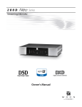
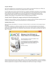
C N Word Clock Distripalyzer . DCD-8 EN TS ,I A Distributor, a Stripper and an Analyzer Operation Manual A U D IO R Software version 1.03 BRAINSTORM ELECTRONICS, INC. ...Intelligent Solutions For The Recording Studio DCD-8 TS ,I N C . Word Clock Distripalyzer Owner’s manual EN Version 1.0.3 Sept. 2006 R All materials herein © Brainstorm Electronics, Inc. D IO Brainstorm Electronics reserves the right to change or modify the contents of this manual at any time. A U Credits Concept: AID, Brainstorm Electronics Software: Gerry Lester Manual: Bernard Frings, Gerry Lester Technical Assistance: Jeff Evans, Jim Pace Brainstorm Electronics, Inc. 5100 Goldleaf Circle, 215 - Los Angeles, CA 90056 - USA - Tel: +1/323/845-1171 www.brainstormtime.com Page 2 DCD-8 User Manual Table of contents 1. INTRODUCTION . . . . . . . . . . . . . . . . . . . . . . . . . . . . . . . . . . . . . . . . . . . . . . . . . . . 3 2. I/O’S DESCRIPTION AND CABLE REQUIREMENTS ........................4 3. INSTALLATION . . . . . . . . . . . . . . . . . . . . . . . . . . . . . . . . . . . . . . . . . . . . . . . . . . . . 5 4. QUICK START . . . . . . . . . . . . . . . . . . . . . . . . . . . . . . . . . . . . . . . . . . . . . . . . . . . . 5 ......................................6 . 5. FRONT PANEL DISPLAY & LED’S C 6. NAVIGATION KEYS . . . . . . . . . . . . . . . . . . . . . . . . . . . . . . . . . . . . . . . . . . . . . . . . 7 N 7. MENU NAVIGATION . . . . . . . . . . . . . . . . . . . . . . . . . . . . . . . . . . . . . . . . . . . . . . . 8 IO R EN TS ,I 8. MENUS DESCRIPTION . . . . . . . . . . . . . . . . . . . . . . . . . . . . . . . . . . . . . . . . . . . . . . 9 01- Rate A . . . . . . . . . . . . . . . . . . . . . . . . . . . . . . . . . . . . . . . . . . . . . . . . . . 9 02- Reference A . . . . . . . . . . . . . . . . . . . . . . . . . . . . . . . . . . . . . . . . . . . . . . 9 03- Alternate Reference . . . . . . . . . . . . . . . . . . . . . . . . . . . . . . . . . . . . . . . . . 9 04- Word Clock Out . . . . . . . . . . . . . . . . . . . . . . . . . . . . . . . . . . . . . . . . . . 10 05- Audio Out . . . . . . . . . . . . . . . . . . . . . . . . . . . . . . . . . . . . . . . . . . . . . . 10 06- Audio In A . . . . . . . . . . . . . . . . . . . . . . . . . . . . . . . . . . . . . . . . . . . . . . 10 07- Audio In B . . . . . . . . . . . . . . . . . . . . . . . . . . . . . . . . . . . . . . . . . . . . . . 10 21- Rate B . . . . . . . . . . . . . . . . . . . . . . . . . . . . . . . . . . . . . . . . . . . . . . . . . 11 22- Reference B . . . . . . . . . . . . . . . . . . . . . . . . . . . . . . . . . . . . . . . . . . . . . 11 31- DCD-8 Link . . . . . . . . . . . . . . . . . . . . . . . . . . . . . . . . . . . . . . . . . . . . . 11 32- Optical I/O . . . . . . . . . . . . . . . . . . . . . . . . . . . . . . . . . . . . . . . . . . . . . 11 33- AES Input Default Clock Source . . . . . . . . . . . . . . . . . . . . . . . . . . . . . . . 12 41- Input Status . . . . . . . . . . . . . . . . . . . . . . . . . . . . . . . . . . . . . . . . . . . . . . 12 42- Termination . . . . . . . . . . . . . . . . . . . . . . . . . . . . . . . . . . . . . . . . . . . . . . 12 91- Menu Lockout . . . . . . . . . . . . . . . . . . . . . . . . . . . . . . . . . . . . . . . . . . . . 12 92- Settings . . . . . . . . . . . . . . . . . . . . . . . . . . . . . . . . . . . . . . . . . . . . . . . . 13 99- DCD-8 Software version & FW Serial No . . . . . . . . . . . . . . . . . . . . . . . 13 9. NON-VOLATILE STORAGE . . . . . . . . . . . . . . . . . . . . . . . . . . . . . . . . . . . . . . . . . . 13 10. LOCK STATUS . . . . . . . . . . . . . . . . . . . . . . . . . . . . . . . . . . . . . . . . . . . . . . . . . . . 14 D 11. DEFINING THE RATE: Set, Auto & Learn . . . . . . . . . . . . . . . . . . . . . . . . . . . . . . . 14 U 12. ALTERNATE REFERENCE . . . . . . . . . . . . . . . . . . . . . . . . . . . . . . . . . . . . . . . . . . . 16 A 13. AUDIO ROUTING . . . . . . . . . . . . . . . . . . . . . . . . . . . . . . . . . . . . . . . . . . . . . . . . 17 14. REF B . . . . . . . . . . . . . . . . . . . . . . . . . . . . . . . . . . . . . . . . . . . . . . . . . . . . . . . . . 18 15. FIREWIRE . . . . . . . . . . . . . . . . . . . . . . . . . . . . . . . . . . . . . . . . . . . . . . . . . . . . . . 19 16. DCD-Link . . . . . . . . . . . . . . . . . . . . . . . . . . . . . . . . . . . . . . . . . . . . . . . . . . . . . . 19 17. UPDATING THE DCD-8 FIRMWARE . . . . . . . . . . . . . . . . . . . . . . . . . . . . . . . . . . . 19 18. APPENDIX . . . . . . . . . . . . . . . . . . . . . . . . . . . . . . . . . . . . . . . . . . . . . . . . . . . . . 20 Pulled Rates . . . . . . . . . . . . . . . . . . . . . . . . . . . . . . . . . . . . . . . . . . . . . . . . . 20 Multiplier Rates . . . . . . . . . . . . . . . . . . . . . . . . . . . . . . . . . . . . . . . . . . . . . . 20 Error Messages . . . . . . . . . . . . . . . . . . . . . . . . . . . . . . . . . . . . . . . . . . . . . . 21 Digital Audio Formats . . . . . . . . . . . . . . . . . . . . . . . . . . . . . . . . . . . . . . . . . 23 Video Input Formats . . . . . . . . . . . . . . . . . . . . . . . . . . . . . . . . . . . . . . . . . 23 Factory Default Settings . . . . . . . . . . . . . . . . . . . . . . . . . . . . . . . . . . . . . . . . 23 User Settings . . . . . . . . . . . . . . . . . . . . . . . . . . . . . . . . . . . . . . . . . . . . . . . . 24 DCD-8 User Manual Page 3 1. Introduction Congratulations on purchasing the DCD-8 Word Clock Distripalyzer. In the tradition of the Brainstorm Distripalyzers, the DCD-8 is a Word Clock distributor, striper and analyzer. Inside the DCD-8 is a very flexible generator with ultra low-jitter. With its many I/O’s the DCD-8 is a complete word clock solution. It’s main features include: C N 1.1. SYSTEM ARCHITECTURE . Word clock generator Word clock extractor Word clock distributor Digital Audio router Format converter Word clock analyzer Video Sync Generator (optional) TS ,I • • • • • • • The DCD-8 generator has 2 domains, A & B, each capable of generating a different rate. Any rate can be generated, up to 192KHz. The DCD-8 can be referenced to any of the inputs: WC, AES, S/PDIF, FireWire, Optical, video or internal crystal. EN The A and the B rates can be assigned to any word clock BNC output and audio output, as silent audio. R WC GENERATOR “A” DOMAIN Rate selection “B” DOMAIN Rate selection U D WC GENERATOR OPTICAL 1392 S/PDIF AES 3 REFERENCE SELECTOR AES 2 AES 1 INTERNAL VIDEO OPTICAL 1392 S/PDIF AES 3 IO AES 2 AES 1 WC 3 WC 2 WC 1 In addition, each domain can re-clock any audio input and route it to any audio output. AUDIO INPUT SELECTOR AUDIO RECLOCKING “A” Domain A AUDIO RECLOCKING “B” Domain HD VIDEO SYNC GEN 1 HD VIDEO SYNC GEN 2 Domain Select Domain Select Domain Select Domain Select Source Select Source Select Source Select OPT OUT 1392 OUT MULTIPLIER HD OUT 1 UTS (optional) HD OUT 2 BNC OUT 1&2 BNC OUT 3&4 BNC OUT 5&6 WORD CLOCK OUTPUTS BNC OUT 7&8 AES/EBU OUT S/PDIF OUT AUDIO OUTPUTS Page 4 DCD-8 User Manual 2. I/O’s Description and Cable Requirements 2 3 4 5 6 1. POWER 7 8 9 10 6. AES/EBU OUT . 1 2 XLR male connectors - Transformer isolated balanced outputs for AES3 or AES11. The external power supply provided with the DCD-8 can accept 100 to 240 VAC input at 50 - 60 Hz so it is suitable for use anywhere in the world. Use standard 3-conductor shielded 110Ω XLR cables. 2. 1394 This IEEE 1394 I/O is used to send /receive digital audio to /from a FireWire device. Use standard 6-pin FireWire 400 cables. 3. OPTICAL R IO 2 RCA connectors - I/O. transformer isolated Used for coaxial S/PDIF. Used also to link multiple DCD-8’s together (see menu 31). D Use standard 75Ω RCA coaxial cables. 5. AES/EBU IN N IMPORTANT NOTES: • This input is unterminated. If the DCD-8 is the last item in the chain, it needs to be terminated by placing a 75Ω terminator on the loop BNC. • If the video reference is HD analog reference signal, we recommend NOT daisy-chaining it. Use a standard 75Ω video cable. Use standard optical fiber cables. 4. S/PDIF 2 BNC connectors - Input & Loop through Video Ref can be NTSC, PAL or HD analog reference signal EN Optical transmitter & receiver - this I/O can be used with ADAT or S/PDIF optical audio signals. See menu 32 for selecting the appropriate format. 7. VIDEO REF (IN & LOOP) TS ,I Use the standard IEC power cable supplied. C The DCD-8 requires 12VDC @ 25W. Acceptable voltage range is 12VDC -10% thru 18VDC +10%. U 2 XLR female connectors - Transformer isolated balanced inputs; accepts AES3 or AES11. 2 BNC connectors - Transformer isolated WC inputs Internally terminated with 75Ω. Use standard 75Ω coaxial BNC cables. 9. WORD CLOCK OUT 8 BNC connectors - WC outputs grouped in 4 pairs: 1&2, 3&4, 5&6, 7&8. Use standard 75Ω coaxial BNC cables. 10. VIDEO SYNC GEN OUT (Optional) For info, see the Video Sync Generator’s manual. A Use standard 3-conductor shielded 110Ω XLR cables. 8. WORD CLOCK IN 11 12 11. WORD CLOCK INPUT 3 - FRONT PANEL 12. AES/EBU INPUT 3 - FRONT PANEL 1 BNC connector - transformer isolated This connector is identical to the other 2 WC inputs on the rear panel. 1 BNC connector - transformer isolated This front panel BNC accepts unbalanced AES/EBU input (AES3id). Use a standard 75Ω coaxial BNC cable. Use a standard 75Ω coaxial BNC cable. DCD-8 User Manual Page 5 3. Installation 3.1. UNPACKING When unpacking the DCD-8 the following items should be in the shipping carton: • • • • DCD-8 unit Universal Power Supply (12VDC @ 25w) IEC power cable Owner’s Manual & Registration card . 3.2. INSTALLING THE DCD-8 C The DCD-8 is designed to be mounted in a standard 19” rack. It requires 1U in height. Ideally, it should be located near your AD/DA and in the same rack. N Usual precautions should be respected when wiring the DCD-8: use high quality cables with good shield to guarantee a good signal transmission. Keep your cables as short as possible. TS ,I Devices connected to the DCD-8’s WC outputs need to be terminated. If no termination is provided on the device, use a BNC-T with a 75Ω termination. If multiple devices are connected to a single DCD-8 WC output, only the last device in the chain should be terminated. However, to preserve the integrity of the transmission line, it is recommended that you do not daisychain word clock outputs as it can significantly degrade signal quality. EN 4. Quick Start The DCD-8 is very versatile and can accommodate many different situations. You should read through this manual to familiarize yourself with its many features. The following few simple steps are only provided to get you started right away. R Connect the power supply provided with the DCD-8 to the 4 pin DIN power connector on the rear panel and plug the IEC cable into a proper wall outlet. This turns on your unit. IO If the unit has already been used, please refer to page 13 to reset the factory settings. If not, out of the box, the DCD-8 is set to generate a 48KHz Word Clock, referenced to its internal crystal. This rate is fed to all 8 WC outputs, as well as all 5 audio outputs (as silent audio). 4.1. CHANGING THE RATE A U D To select a different rate, follow these steps: • • • • • Press the [SET UP] key (the SET UP LED lights up) In Menu 01, press the [RIGHT] navigation key once to move to the Rate field Press the [UP] or [DOWN] keys to select the desired rate Press the [ENTER] key to confirm your choice Press the [SET UP] key again to exit SET UP (the Set Up LED goes out) Your selection is reflected in the upper right corner of the LCD display, following FQ A. 4.2. CHANGING THE REFERENCE To select a different reference, follow these steps: • • • • • • Press the [SET UP] key (the SET UP LED lights up) Press the [UP] key once to go to Menu 02 Press the [RIGHT] navigation key once to go to the REF selection Press the [UP] or [DOWN] keys to select the desired reference Press the [ENTER] key to confirm your choice Press the [SET UP] key again to exit SET UP (the Set Up LED goes out) Your selection is reflected in the upper left corner of the LCD display, following REF. Page 6 DCD-8 User Manual 5. Front Panel Displays & LED’s The DCD-8 has been designed so that most of the relevant information would always be available at a glance on it’s front panel. The 80 character LCD is broken into three separate areas: C . 5.1. LCD DISPLAY Left: displays the currently selected reference and it’s frequency • Center: shows the Lock Status • Right: displays the selected A & B frequencies. TS ,I N • Selected Reference A & B Frequencies EN Lock Status 5.2. OUTPUT ASSIGNMENTS LED’S R To know what signal has been assigned to each output, there are 22 LED’s describing the selections made. Word Clock Outputs: A-B IO These LED’s indicate which frequency has been assigned to each WC output pair: A or B. D For WC Outputs 7&8, 5 LED’s indicate if a multiplier has been applied. A U Audio Outputs: A-B-Audio • If ‘Audio’ is off, the output is silent audio at the A or B rate; LED’s indicate which. • If ‘Audio’ is on, the output is the audio source selected in menu 6 for A or 7 for B. 5.3. WC GEN LED’S 4 different “pull” coefficients are available. Each has a corresponding LED for A and B domains: • + 4.16% • + 0.1% • - 0.1% • - 4.0% These coefficients can be combined to create +4.27% and -4.096%. VSO (varispeed) LED indicates that another rate (non-standard) is generated. DCD-8 User Manual Page 7 5.4. WARNING LED’S REF ERROR: a failure of the selected reference occurred ALT REF: the DCD-8 had to switch to the alternate reference PHASE ERROR: one of the inputs is out of phase (see menu 41) TERMINATION: a unit connected to one of the WC outputs is improperly terminated (see menu 42) B REFERENCE: domain B is not using the same reference as domain A N These LED’s are only active if the optional Video Sync Generator card has been installed in your DCD-8. C . 5.5. VIDEO SYNC LED’S EN TS ,I For information on these LED’s, please refer to the manual of the optional Video Sync Generator card. 6.1. SET UP KEY R 6. Navigation Keys To access the different menus, press the [SET UP] key. IO While in SET UP mode, the Set Up LED is on. Left Right Down U D To exit the SET UP mode, simply press the [SET UP] key again. Up A 6.2. ENTER KEY Scrolling through the different values will not affect anything. Only after the [ENTER] key is pressed will a change take place. When exiting a menu without pressing the [ENTER] key, the changes are lost. 6.3. UP, DOWN, LEFT, RIGHT KEYS These keys are directly left of the [ENTER] and [SET UP] keys. They are not labeled as such because their function is fairly obvious. While in Set Up mode, the [UP] and [DOWN] keys are used to change the value of the selected field, while the [LEFT] and [RIGHT] keys are used to select the different fields. [UP] and [DOWN] keys are also used to change menu pages. Page 8 DCD-8 User Manual 7. Menu Navigation 7.1. SELECTING A MENU . When the Set Up mode is entered, the LCD display switches to the Set Up menu last used, with the cursor on the far left position in the upper line. N C To move to another menu, with the cursor on the upper left position, press the [UP] or [DOWN] key. 7.2. CHANGING VALUES TS ,I To edit one of the fields on the current menu, press the [RIGHT] or [LEFT] key to move the cursor to the desired field. Then, press the [UP] or [DOWN] key to change the value. Note that no change will take effect until the [ENTER] key is pressed. When exiting a menu without pressing the [ENTER] key, the changes are lost. EN 7.3. THE CURSOR The cursor position is indicated with a ‘>’ character, implemented as inverse video, flashing on and off. For numeric entry such as the VSO value, an additional underline cursor appears beneath the digit column being adjusted. IO R After a value is edited, the cursor changes to a solid triangle, until the [ENTER] key is pressed. U D If the cursor is moved to another field without pressing the [ENTER] key first, the solid triangle stays in front of the edited field to indicate a change was made but not entered yet. A 7.4. STATUS VALUES Throughout he different menus, values appear in the display enclosed in square brackets. These are status values. Status values are the values actually obtained, based on a menu selection. In some cases, this might be a rate in Hz. In others it might be a different value if the one asked for is unavailable. For example, in menu 5, if Audio is unavailable [Mute] will be displayed. 7.5. SET VS. AUTO VS. LEARN The words “Set”, “Auto” and “Learn” are used to distinguish whether the user is establishing the value (Set) or if the system is deducing the value automatically (Auto & Learn). See chapter 11 for more information on these functions. DCD-8 User Manual Page 9 8. Menus Description Chapter 8 lists all the different menus available in the SET UP mode. Note that some of the menu options will change based on your selections. As an example, if S/PDIF has been selected in menu 32 as the optical connector format, ADAT no longer appears as a reference option in menu 02, and vide-versa. C . 8.1. MENU 01: RATE A TS ,I N In SET mode, a specific frequency can be selected; in AUTO mode, the reference’s rate is automatically selected. AUTO mirrors the reference selection. AUTO is not available if the reference is Internal Crystal or Video. VSO can be activated in SET mode. VSO range is +/- 5% in .001% steps or .001 semi-tone. Please note that VSO is not implemented in software version 1.03. Status is the actual rate in Hz. R EN 8.2. MENU 02: REFERENCE A Select any of the available external sources as reference or use the internal crystal. AES 1 AES 2 AES 3 S/PDIF ADAT Optical (S/PDIF) 1394 Video A U D IO Choices are: Internal Word Clock 1 Word Clock 2 Word Clock 3 When selecting any of the external sources, a RATE menu appears on the bottom line. RATE has 2 modes: - LEARN: the DCD-8 determines the incoming rate; - SET: the user determines the incoming rate. For more information on Set vs. Learn, go to chapter 11. 8.3. MENU 03: ALTERNATE REFERENCE A The alternate reference is used as a backup reference in case the main reference fails. If it happens, the DCD-8 smoothly switches to the alternate reference. For more on Alternate Reference, see chapter 12. Similar to menu 02, when selecting any of the external sources, a RATE menu appears on the bottom line. The RATE can be on AUTO or SET. Page 10 DCD-8 User Manual 8.4. MENU 04: WORD CLOCK OUT Word Clock outputs are adjustable in pairs. For each pair, the choice is A or B, referring to the rates set in menus 01 and 21. C . Outputs 7 & 8 can also add a multiplier to the A or B rates (see Appendix 2). Note that only the available choices will be displayed. TS ,I N 8.5. MENU 05: AUDIO OUT EN For each Audio Out, the choices are: • A.Mute Silent audio at the A rate • A.Audio Re-clocked audio source A as selected in menu 06 • B.Mute Silent Audio at the B rate • B.Audio Re-clocked audio source B as selected in menu 07 NOTE: The AES Audio Out includes all AES and S/PDIF outputs. If audio is unavailable, status indicates [Mute] IO R 8.6. MENU 06: AUDIO IN A D The selected audio source can be re-clocked in domain A and routed to any of the audio outputs in menu 05. For more on Audio Routing, see chapter 13. A U NOTE: this re-clocking occurs in the A domain. If your audio source is not synchronous with the A rate, sound degradation will occur. If the input selected is unavailable, the status is [OFF] and an error message appears (see appendix 3). 8.7. MENU 07: AUDIO IN B Menu 07 is identical to menu 06, for domain B. DCD-8 User Manual Page 11 8.8. MENU 21: RATE B Menu 21 is identical to Menu 01, for domain B C . 8.9. MENU 22: REFERENCE B N Under most circumstances, the B domain will use the same reference as A. However, if necessary, a separate reference can be selected for B. TS ,I This menu is identical to menu 02, for domain B, with one additional choice: ‘Use REF A’ (default setting). For more on Ref B, go to Chapter 14, page 18. EN CAUTION: When selecting a reference in menu 22, domains A and B no longer share the same reference. To alert the user of this condition, a front panel warning LED turns on, labeled “B Reference”. R 8.10. MENU 31: DCD-8 LINK IO When using multiple DCD-8 together and the optional video sync generator the DCD-link feature guarantees that they stay in phase. The S/PDIF port is used for this link (RCA connectors). A U D The choices are: Off Transmit Receive, re-transmit When DCD-Link is set to ‘Receive & re-transmit’, the Reference is automatically changed to DCD-Link. This advanced feature is not implemented in version 1.03. 8.11. MENU 32: OPTICAL I/O Optical I/O can be set to ADAT or S/PDIF Optical. Changing this setting may cause an error of this I/O was selected as a reference or an audio source (see appendix 3 for more on error messages). Page 12 DCD-8 User Manual 8.12. MENU 33: AES INPUT DEFAULT CLOCK SOURCE When any AES or S/PDIF source is used as a reference or as an audio source, it is automatically used as the default clock source, in that order of priority. If not, the user can determine in this menu which AES or S/PDIF source to use as the clock source. This will be used by the DCD-8 primarily for measurements (frequency & phase). C . In AUTO mode, the DCD-8 scans through each input and selects the first valid signal it finds. When no AES inputs are connected, status indicates [Scanning]. TS ,I N 8.13. MENU 41: INPUT STATUS This menu displays the rate and phase information for each input. To view a different input, go to the input field and use the [UP] and [DOWN] keys. EN Note that the phase information is not implemented in software version 1.03. R 8.14. MENU 42: TERMINATION IO This pages shows a termination measurement for each of the 8 word clock outputs. These measurements are not meant to be accurate, but to give an indication. D Ideally, the value displayed should be 75Ω. If < 48Ω, the word ‘Double’ is displayed; if < 30Ω, ‘Triple’; if >500Ω, ‘Open’. If any output is double or triple-terminated, the TERMINATION warning LED lights up. A U To view a different output, go to the output field and use the [UP] and [DOWN] keys. NOTE: These are DC measurements. It may not measure AC coupled inputs correctly. 8.15. MENU 91: MENU LOCKOUT To prevent accidental changes, the DCD-8 menus can be locked out. In this mode, no changes are permitted. If a change is attempted while the menus are locked out, an error message appears on the LCD display: “ERROR - Menus Locked Out.” DCD-8 User Manual Page 13 8.16. MENU 92: SETTINGS This menu is used to store and recall user presets. The DCD-8 has provisions to store up to 4 different presets, labeled USER 0 through USER 3. . To store a preset, select SAVE. Then select the user preset number you would like to save to and press [ENTER]. N C To recall a preset, select RECALL. Then select the user preset number you would like to recall and press [ENTER]. TS ,I FACTORY DEFAULTS: There is an additional preset holding the Factory Defaults. This preset can only be recalled and cannot be modified. EN For details on the Factory Defaults, see Appendix 5. R 8.17. MENU 99: DCD-8 SOFTWARE VERSION IO This menu displays the unit’s software version number and its FireWire serial number. To update the software version, refer to chapter 17. U D The FireWire serial number is pre programmed at the factory and cannot be changed. Identification over FireWire has to be different for each DCD-8 so that more than one of them can co-exist on the same bus. A 9. Non-Volatile Storage The DCD-8 has 4 user presets and a factory default preset (see menu 92 above). In addition, it has non-volatile memory holding the current settings. This includes all DCD-8 settings such as rate and reference selections as well as output assignments. This memory is continuously updated so that, when the unit is turned on, it is in the same condition as it was when powered down. NOTE: You should wait approximately 10 seconds after a change was entered before powering down, to allow for the flash memory to be updated. Page 14 DCD-8 User Manual 10. Lock Status Reference missing Unable to lock PLL is trying to lock Loose Lock Lock confirmation phase Good and locked Holding last known frequency after lock failure N C NO REF UNLOCKED SLEW LOCKED -LOCKED LOCKED HOLDING . The lock status of the DCD-8 is displayed in the center of the LCD display. Below are the 7 different possibilities and what they indicate: TS ,I The DCD-8 always tries to lock to it’s input. Once the rate has been established (SET or LEARN), if the reference is off speed by more than 10%, it switches to SLEW. Note that with video, the 10% rule applies to the horizontal frequency and not the frame rate. EN 11. Defining the rate: Set, Auto & Learn Part of the DCD-8’s great flexibility comes from the fact that the rate generated does not have to match the rate of the reference. Different frequencies can be cross-locked if necessary. But the DCD-8 can also be set up to simply generate the reference frequency. 11.1. RATE MENU R This is done through the use of the SET, AUTO and LEARN functions. IO In the Rate menu, the DCD-8 offers a choice between SET and AUTO. With SET, the user can select a specific rate. With AUTO, the DCD-8 determines the rate, based on the selection made in the Reference menu. AUTO simply mirrors the Reference menu. A U D NOTE: Auto is not available if the reference selected is Internal or Video. 11.2. REFERENCE MENU In the Reference menu, the DCD-8 offers a choice between LEARN and SET. In the LEARN mode, the DCD-8 measures the input reference and determines it’s rate. In SET, the user determines it. Most of the time LEARN will work fine. However, at times, the user may choose SET to be sure the DCD-8 does not misinterpret an input frequency which is slightly incorrect. The Set mode may also be chosen for more failsafe operation, in that there is no chance that the DCD-8 will re-define a frequency which drifts over time. DCD-8 User Manual Page 15 11.3 ABOUT USING THE SET MODE FOR THE REFERENCE WARNING: It is very important to understand that SET (in the REF menu) overrides the DCD-8. When using this function, the user can potentially mislead the DCD-8 and affect the output frequency, even if that is also SET. This could be intentional. But caution should be used here. When SETTING the rate of the reference, there is the possibility that the selected rate will not match the measured rate (actual rate). If that is the case, the DCD-8 will still lock to the reference but the output frequency will be adjusted proportionately. C . In the second illustration below, with the NTSC video reference is SET as PAL, the A frequency SET at 44100Hz will actually be 52867Hz (25/29.97 x 44100 = 52867). N 11.4 OFF SPEED INDICATION TS ,I When the reference is detected to be off speed by more than 1.5%, the DCD-8 alerts the user as follows. The main display alternates between the normal LOCKED status and the OFF SPEED indication, staying about 2 seconds on each one. The measured reference frequency is shown under the words ‘Off Speed’ for comparison with the nominal rate, shown under the reference. EN Here is an example of the Off Speed indication for Ref A WC1. IO R For comparison, here is another example for Ref A Video, off speed: 11.5 HOW ALL THIS WORKS D To help understand how these different modes interact, let’s take a look at a few examples. A U • • Ref: LEARN & Rate: AUTO 48.003k in = 48.003k out 44.1k in = 44.1k out In this case, no rate needs to be programmed. The DCD-8 learns the incoming rate and regenerates it. What comes in is what comes out. Ref: LEARN & Rate: SET (48k) 48.003k in = 48.003k out 44.1k in = 48k out Here, if the DCD-8 detects that the input rate has changed, it makes the necessary adjustments to maintain the output rate as set. • Ref: SET (48k) & Rate: AUTO 48.003k in = 48.003K out 44.1k in = 44.1k out (OS message) When set on AUTO, the rate mirrors the reference. The OFF SPEED message will appear on the LCD if the reference is off (44.1). • Ref: SET (48k) & Rate: SET (44.1k) 48.003k in = 44.103k out 44.1k in = 40.517k out (OS message) With Ref in SET, if the input rate is different than what was set, the DCD-8 applies the off-speed ratio to the SET output frequency Note: 48.003 is only used in these example to illustrate that the DCD-8, when locked to the reference, will track small variations. Page 16 DCD-8 User Manual 12. Alternate Reference If the external reference fails, the DCD-8 has 2 different ways of insuring that the WC output remains safely uninterrupted. 12.1. MAIN REFERENCE FAILURE WITH AN ALTERNATE REFERENCE SET If an alternate reference was set in menu 3, the DCD-8 goes into the following cycle: C . • Step 1: When a failure occurs, 2 things happen immediately: - the PLL switches to the Alternate Reference - the generator goes in HOLDING mode, holding the last known frequency. • Step 2: After about 2 seconds, the generator switches smoothly to the alternate reference. N During Step 1, the LCD display indicates “HOLDING” as the lock status. During Step 2, the lock status goes from ‘LOCKED --” to “LOCKED” as it reaches full lock. TS ,I If the Alternate Reference fails, the DCD-8 goes back through steps 1 and 2, but this time, Internal Crystal is used as the new reference. 12.2. MAIN REFERENCE FAILURE WITH NO ALTERNATE REFERENCE SET EN If no alternate reference was set in menu 3, the DCD-8 holds the last known frequency and displays “HOLDING” in the LCD display. R If a signal is still present at the main reference input, the DCD-8 attempts to lock to it again. If it succeeds, it goes through the normal ‘Locked’ sequence; if not, it continues holding and attempts to Lock to the main reference again. IO If no signal is present at the main reference input, the DCD-8 will remain in ‘HOLDING’ mode indefinitely. 12.3. REVERT TO REF A A U D After a failure of the main reference, the following error message appears on the lower line of the LCD display: “PRESS ENTER FOR OPTIONS” This message flashes to alert the user of the problem, along with the REF ERROR LED. After pressing the [ENTER] key, the options available are: - EXIT WITH NO CHANGE - CLEAR REF ERROR - RETRY REF A DCD-8 User Manual Page 17 The third option, RETRY REF A, is only available if an Alternate Reference has been set in menu 03. If no Alternate Reference was set, the DCD-8 will automatically retry Ref A. NOTE: When reverting to Ref A, the transition will be smooth, but only if the DCD-8 was locked to either the alternate reference or the internal crystal before selecting RETRY REF A. 12.4. ERROR MESSAGES The following messages appear in the LCD display when appropriate: . REF RETRY FAILED REF RETRY REQUIRE PLL RESET (DCD-8 was not locked - see NOTE above) C 12.5. WARNING LEDS This green LED lights up as soon as the DCD-8 switches to the alternate reference. It flashes if the Alternate Reference fails. TS ,I ALT REF: N REF ERROR: This red LED flashes as soon as the main reference fails. 12.6. REF B R 13. Audio Routing EN Under most circumstances, REF A will be used by domains A & B. However, in menu 07, a separate reference can be set for domain B. But, the Alternate Reference option is only available for the main reference (REF A) and not REF B. If REF B fails, it will go through the procedure described in 12.2 on the previous page. IO One of the features of the DCD-8 is to re-clock an audio input and route it to an audio output. To route audio through the DCD-8, an input must first be selected in menu 06 or 07 (the DCD-8 allows 2 separate inputs to be selected, one for domain A and one for domain B). D • SELECT AN INPUT: A U • SELECT AN OUTPUT: That input must then be assigned to an output. In menu 05, under the desired output, select ‘A.Audio’ to assign the A input or ‘B.Audio’ to assign the B input. On the front panel, under ‘Output Assignments’, the AUDIO LED’s indicate that audio is being routed; at the same time, the A and B LED’s indicate which input is being routed. WARNING: When routing audio through the DCD-8, the audio is re clocked in either domain A or B. It is imperative that the audio source be synchronous with the domain selected. Otherwise, signal degradation will occur. 13.1. MAPPING OPTION 1: LEFT TO ODD AND RIGHT TO EVEN In menu 06 & 07, when selecting a stereo source as the input (AES or S/PDIF), the DCD-8 gives you the option to map this input to all of the output pairs, including the FireWire and ADAT connectors. This means that the left channel would go to channels 1,3,5,7 and the right channel to 2,4,6,8. They would also go to all the stereo outputs (AES or S/PDIF). Page 18 DCD-8 User Manual 13.2. MAPPING OPTION 2: 8 CHANNEL ROUTING MAP If not selecting ‘Left to Odd/ Right to Even’, the DCD-8 uses a routing map as described below. This routing map will vary, depending on the rate at which the router is running due to the various bit-splitting formats accepted by the DCD-8 (S/MUX and AES double-wire). For more on digital audio formats, go to Appendix 4 on page 23. FireWire 44.1 to 96k ADAT 44.1 to 48k ADAT S/MUX 88.2 to 96k AES & S/PDIF 44.1 to 96k 1 1&2 AES-1 L 2 2 3&4 AES-1 R 3 3 5&6 AES-2 L 4 4 7&8 AES-2 R 5 5 S/PDIF L 6 6 S/PDIF R 7 7 AES-3/ Optical L 8 8 C N TS ,I FireWire 176.4 to 192k . 1 AES-3 /Optical R ADAT S/MUX IV 176.4 to 192k 1&2&3&4 2 5&6&7&8 AES-1 AES-2 EN 1 AES Double Wire 176.4 to 192k R 14. Ref B IO The DCD-8 has 2 separate domains, A and B. These domains are used to generate multiple rates simultaneously. Under most circumstances, both domains will use the same reference. Therefore, the default setting for Ref B (menu 22) is ‘USE REF A”. D However, if necessary, a separate reference can be selected for domain B. In essence, this would be separating the DCD-8 in 2 completely independent units. NOTE: A warning LED lights up on the front panel to alert the user. A U When setting a separate reference for B, the main menu will reflect this. However, the amount of information displayed will be reduced, due to the space available. Both references will be displayed, but not their frequency. Similarly, when displaying Off Speed condition (see chapter 11), the measured frequency will not be displayed. Those missing frequency indications normally appear on the bottom line, which is used up here for Ref B. DCD-8 User Manual Page 19 15. FireWire The DCD-8 includes a FireWire I/O which is used to transmit and receive digital audio as well as to update the current software version (see chapter 17). Drivers for PC and Mac are available for download at www.brainstormtime.com. Once installed, the DCD-8 should be recognized by your computer as an 8 channel device. The DCD-8 can lock to the clock coming from the FireWire audio and clean it up. It can also re-clock and route audio to and from a FireWire device. N C . The FireWire audio is not implemented yet in version 1.03. TS ,I 16. DCD-Link Multiple DCD-8’s can be linked together by simply connecting an output from the Master DCD-8 into the slave DCD-8 and selecting it as the reference on the slave DCD-8. The DCD-link option goes a little further by keeping multiple DCD-8’s and the optional video sync generator in phase. EN DCD-Link is activated in menu 31. The master unit should be on ‘Transmit’ and the slave unit(s) on ‘Receive and re-transmit’. Connect a 75Ω coaxial cable between the DCD-Link OUT (RCA - S/PDIF OUT) on the master unit and the DCD-Link IN on the slave unit. IO R The reference on the slave DCD-8 is automatically changed to ‘DCD-Link’ and the reference rate is shown on the LCD display. D DCD-Link is not implemented in version 1.03. A U 17. Updating the Firmware You should compare your software version number (menu 99) to the latest version number, as listed on our web site. If not current, you should update your DCD-8. Updating the software version is done through the FireWire port. It can be done with a Mac or a PC. The procedure is similar for both computers: 1. Install the DCD-8 driver on your computer (this would have already been done if you are using FireWire audio) 2. Connect a FireWire cable between the DCD-8 and your computer 3. Run the Firmware Loader software on your computer 4. Load the new file into the DCD-8, replacing the old one 5. Exit the Firmware Loader 6. Power down the DCD-8 then power up again 7. Go to Menu 99 to verify the current software version number. Page 20 DCD-8 User Manual These are the files available for download from our web site (www.brainstormtime.com): • • • • DCD-8 driver (PC and Mac) Firmware loader (PC or Mac) DCD-8 current software Installation instructions (PC and Mac) Please note that only registered users are allowed to download these files so be sure to register your unit as soon as possible. C . A CD containing these files can also be purchased. Please contact us for more information. N 18. Appendix TS ,I 18.1. PULLED RATES Here is a list of the standard and pulled rates generated by the DCD-8. -4.096% (25 to 23.976 f/s) 42,294 84,587 169,175 -4.0% (25 to 24 f/s) 42,336 84,672 169,344 -0.1% (30 to 29.97 f/s) 44,056 88,112 176,224 44,100 88,200 176,400 (29.97 to 30 f/s) 44,144 88,288 176,576 (24 to 25 f/s) 45,938 91,875 183,750 +4.2709% (23.976 to 25 f/s) 45,983 91,967 183,934 -4.096% (25 to 23.976 f/s) +0.1% +4.166% EN BASE RATE 92,068 184,136 -4.0% 46,080 92,160 184,320 -0.1% (30 to 29.97 f/s) 47,952 95,904 191,808 48,000 96,000 192,000 (29.97 to 30 f/s) 48,048 96,096 192,192 (24 to 25 f/s) 50,000 100,000 200,000 (23.976 to 25 f/s) 50,050 100,100 200,200 R 46,034 (25 to 24 f/s) IO BASE RATE +0.1% +4.166% U D +4.2709% A 18.2. MULTIPLIER RATES Through WC outputs 7&8, the DCD-8 can apply a multiplier to the selected base frequency. Here is a list of the available rates. An ‘X’ indicates this choice is not available. FSx1 FSx2 FSx4 FSx64 FSx128 FSx256 192 KHz 192.0KHz X X 12.2880MHz X X 176 KHz 176.4KHz X X 11.2896MHz X X 96 KHz 96.0KHz 192.0KHz X 6.1440MHz 12.2880MHz X 88 KHz 88.2KHz 176.4KHz X 5.6448MHz 11.2896MHz X 48 KHz 48.0KHz 96.0KHz X 3.0720MHz 6.1440MHz 12.2880MHz 44 KHz 44.1KHz 88.2KHz X 2.8224MHz 5.6448MHz 11.2896MHz 32 KHz 32.0KHz 64.0KHz X 2.0480MHz 4.0960MHz 8.1920MHz DCD-8 User Manual Page 21 18.3. ERROR MESSAGES When a faulty value is selected, an error message is displayed as soon as the [ENTER] key is pressed. Although the request is not granted, only the [status value] is adjusted, not the selected value. Therefore, every time the [ENTER] key is pressed, the error message reappears. To eliminate this, an ‘acceptable’ value must be entered in the proper menu. Below is a complete list of all the error messages generated by the DCD-8 along with a description and the menus concerned. ERROR: Same audio source both domains Same audio (group) cannot be source to both domains (see menus 06 & 07). TS ,I • N C . NOTE: These messages appear on the LCD display for about 3 1/2 seconds and may be cancelled by any key press. NOTE: the DCD-8 considers all AES & S/PDIF as a single source, as far as the audio router is concerned ERROR: ADAT input selected but not available Can’t choose ADAT as audio source when optical connectors switched to Optical S/PDIF (see menus 06, 07 & 32) • ERROR: AES 3 input selected but not available Can’t choose AES3 as audio source when optical connectors switched to Optical S/PDIF (see menus 06, 07 & 32) • ERROR: Optical input selected but not available Can’t choose Optical S/PDIF as audio source when optical connectors switched to ADAT (see menus 06, 07 & 32) • ERROR: Optical reference not available Can’t choose Optical S/PDIF reference when optical connectors switched to ADAT - may occur when switching the optical input from Optical S/PDIF to ADAT (see menus 02 & 32) D IO R EN • A U • ERROR: Optical choice prevents reference select Can’t choose ADAT or AES3 reference when optical connectors switched to Optical S/PDIF - may occur when switching the optical input from ADAT to Optical S/PDIF (see menus 02 & 32) • ERROR: Menus Locked Out Attempt to change a menu setting while menus are locked out (see menu 91) • • ERROR: REF combination (A, B) unavailable ERROR: REF combination (alt A, B) unavailable Domains A & B cannot have dissimilar AES/SPDIF reference combinations (AES inputs share a single PLL) - (see menus 02 & 22) - The same applies to ALT REF A (menu 03) • • ERROR: REF B same as REF A ERROR: REF B same as ALT REF A The same source cannot be assigned to Ref B and REF A (or ALT REF A). In that case, Ref B reverts to ‘Use Ref A’. Page 22 DCD-8 User Manual The following 3 messages are informative messages. • ERROR: REF Retry failed Original reference found to be missing during Retry • INFO: REF Retry required PLL reset System was not locked when ref Retry requested -- smooth re-lock not attempted and PLL re-started to guarantee synchronization • INFO: Saving User Settings C . System is in the process of saving user settings following a Save request INFO INFO INFO “Learned rate change: REF A” “Learned rate change: REF B” “Learned rate change: ALT REF A” • Off Speed TS ,I • • • N The following 3 are also informative. They display if the reference rate (or alt ref rate) is on LEARN and the incoming rate changes EN This message appears when the reference is detected to be off speed by more than 1.5%. The main display alternates between the normal LOCKED status and the Off Speed indication - staying about 2 sec. on each one. When there is only a single reference (A), the measured reference frequency is shown on the bottom line, for comparison with the nominal reference rate. For additional information, go to chapter 11, on page 15. • R The last type of message is more of a warning message and requires user feedback. Press ENTER for options IO This message appears after a failure of the reference. To alert the user, it flashes continuously on and off on the bottom line of the LCD display, along with the REF ERROR LED. D Pressing the [ENTER] key gives several options. To access these options, use the [UP] and [DOWN] keys. U The options available vary depending on the ALT REF settings (menu 03): A - If an alternate reference had been set and the DCD-8 switched to it: Retry REF A: to attempt to re-clock to the main reference. Clear REF ERROR: this option clears the flashing REF ERROR LED and exits; the DCD-8 stays locked to the alternate reference and the LCD keeps on flashing the ‘Enter for options’ message, offering only options 1 & 3 this time; EXIT with no change: exit but leave everything as is. - If no alternate reference had been set and the DCD-8 is HOLDING: Clear REF ERROR: this option clears the flashing REF ERROR LED and exits; the DCD-8 stays in HOLDING mode; EXIT with no change: exit but leave everything as is. DCD-8 User Manual Page 23 18.4. DIGITAL AUDIO FORMATS The following table lists all the digital audio formats accepted by the DCD-8: Number of channels per connector Connector Valid Rates 2 XLR 44.1-96 KHz AES Double Wire 1 XLR 176.4-192KHz AES3id 2 BNC 44.1-192 KHz S/PDIF Coaxial 2 RCA 44.1-192 KHz S/PDIF Optical 2 TOS-Link 44.1-96KHz ADAT Lightpipe 8 TOS-Link ADAT S/MUX 4 TOS-Link ADAT S/MUX IV 2 TOS-Link FireWire 8 1394 . AES Single Wire C Formats 44.1-48KHz N 88.2-96KHz 176.4-192KHz TS ,I 44.1-192 KHz The DCD-8 accepts AES double-wire, ADAT S/MUX and S/MUX IV. The input formats on the AES / S/PDIF and ADAT connectors will be adjusted based on the REFERENCE; the output formats will be adjusted based on the RATE. EN To run the ADAT input in S/MUX mode, the relevant domain REFERENCE must be forced into the 96000 range (4 channels) or in the 192000 range (2 channels); to run the ADAT output in S/MUX mode, the relevant domain RATE must be forced into the 96000 range (4 channels) or in the 192000 range (2 channels). R All AES, S/PDIF and Optical S/PDIF I/O’s run in standard single-wire mode from 44.1k to 96k and in double-wire mode from 176.4k to 192k range. 18.5. VIDEO INPUT FORMATS IO The following table lists all the video formats recognized by the DCD-8 as reference: A U D 525i/29.97 NTSC 625i/25 PAL 720p/50 720p/59.94 720p/60 1080i/25 1080i/25 295M 1080i/29.97 1080i/30 1080sF/23.976 1080sF/24 1080sF/25 1080sF/29.97 1080sF/30 Not supported are the low frame rate 720p formats. 18.6. FACTORY DEFAULT SETTINGS The following are the factory default settings. Rate A 48000 Hz (SET- VSO off) REF A Internal (LEARN) ALT REF A Off WCLK OUT All outputs on A 1080p/23.976 1080p/24 1080p/25 1080p/29.97 1080p/30 1080p/50 1080p/50 295M 1080p/59.94 1080p/60 Page 24 DCD-8 User Manual All outputs on A.Mute AUDIO IN A Off AUDIO IN B Off RATE B 48000 Hz (Set - VSO off) REF B Use Ref A DCD-Link Off Optical I/O ADAT AES Input Default Clock Source Auto Menu Lockout Off . AUDIO OUT N C These settings can be recalled in menu 92. Use this chart to note your own settings. USER 0 RATE A ALT REF A IO AUDIO IN A R WCLK OUT AUDIO OUT AUDIO IN B D RATE B U REF B A Optical I/O AES In Default Clock Source Menu Lockout USER 1 EN REF A TS ,I 18.7. USER SETTINGS USER 2 USER 3 . C N TS ,I EN R IO D U A BRAINSTORM ELECTRONICS, INC. www.brainstormtime.com Distributed Exclusively by plus24 1155 N. La Brea Avenue, West Hollywood, CA 90038 - USA Tel: (323) 845-1171 - Fax: (323) 845-1170 www.plus24.net