1
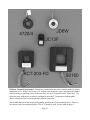
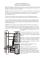
EZ
METER
Watthour Meters
Product Selection Guide
User Manual
Installation Manual
This manual applies to meters that have a letter (A-G) as the
first character of the model number.
CAUTIONS
Legends
Serious injury can result from electric shock.
Be sure to turn off the power before installing or
servicing any meter.
These symbols appear on meter labels.
Fire can result from loose electrical
connections. Ensure that all connections are
secure.
G Equipment protected throughout by double
insulation
1 Caution, risk of Danger
H Alternating Current
A loose or improperly connected neutral can
damage equipment and cause fires. Most meters
that count faster than they should are connected
to a bad neutral.
Abbreviations & Glossary
Common abbreviations used in this manual
include:
Current transformers (CTs) should not be
placed over wires with current flowing through
them without connecting them to the meter or
twisting the two wires coming from the CTs
together. A very serious shock hazard exists if
the wires are just left loose.
AMR - Automatic Meter Reading System
CT - Current transformer
KWH - Kilowatthour
Element - An input for measuring power,
usually a current transformer (CT)
These meters should only be installed by
experienced electricians. If you do not fully
understand these instructions, call the Customer
Support at 1-805-688-9696 or 1-800-824-9696
for clarification.
In most localities, a permit and inspection is
required to install the meters.
Rev. 8/25/2015
i
Contents
CAUTIONS. . . . . . . . . . . . . . . . . . . . . . . . . . . . . . . . . . . . . . . . . . . . . . . . . . . . . . . . . . . . . . . . . . . . . i
Legends. . . . . . . . . . . . . . . . . . . . . . . . . . . . . . . . . . . . . . . . . . . . . . . . . . . . . . . . . . . . . . . . . . . . . . . . i
Abbreviations & Glossary. . . . . . . . . . . . . . . . . . . . . . . . . . . . . . . . . . . . . . . . . . . . . . . . . . . . . . . . . . i
Safety Certification. . . . . . . . . . . . . . . . . . . . . . . . . . . . . . . . . . . . . . . . . . . . . . . . . . . . . . . . . . . Page 3
Accuracy Certification. . . . . . . . . . . . . . . . . . . . . . . . . . . . . . . . . . . . . . . . . . . . . . . . . . . . . . . . . Page 3
A Note for California Users. . . . . . . . . . . . . . . . . . . . . . . . . . . . . . . . . . . . . . . . . . . . . . . . . . Page 3
Limited Warranty. . . . . . . . . . . . . . . . . . . . . . . . . . . . . . . . . . . . . . . . . . . . . . . . . . . . . . . . . . . . . Page 4
Product Selection Guide. . . . . . . . . . . . . . . . . . . . . . . . . . . . . . . . . . . . . . . . . . . . . . . . . . . . . . . Page 5
Automatic Meter Reading (AMR). . . . . . . . . . . . . . . . . . . . . . . . . . . . . . . . . . . . . . . . . . . . . Page 5
Birdirectional Meters. . . . . . . . . . . . . . . . . . . . . . . . . . . . . . . . . . . . . . . . . . . . . . . . . . . . . . . Page 6
Voltage.. . . . . . . . . . . . . . . . . . . . . . . . . . . . . . . . . . . . . . . . . . . . . . . . . . . . . . . . . . . . . . . . . Page 6
Maximum Current and Current Transformers. . . . . . . . . . . . . . . . . . . . . . . . . . . . . . . . . . . . Page 7
Display and Resolution. . . . . . . . . . . . . . . . . . . . . . . . . . . . . . . . . . . . . . . . . . . . . . . . . . . . . Page 7
Enclosures.. . . . . . . . . . . . . . . . . . . . . . . . . . . . . . . . . . . . . . . . . . . . . . . . . . . . . . . . . . . . . . . Page 8
Model Numbers. . . . . . . . . . . . . . . . . . . . . . . . . . . . . . . . . . . . . . . . . . . . . . . . . . . . . . . . . . . Page 8
EZMeter Current Transformers.. . . . . . . . . . . . . . . . . . . . . . . . . . . . . . . . . . . . . . . . . . . . . . Page 11
Operating Instructions. . . . . . . . . . . . . . . . . . . . . . . . . . . . . . . . . . . . . . . . . . . . . . . . . . . . . . . . Page 12
Understanding the Meter Electronics Module Label. . . . . . . . . . . . . . . . . . . . . . . . . . . . . . Page 13
Installation Instructions. . . . . . . . . . . . . . . . . . . . . . . . . . . . . . . . . . . . . . . . . . . . . . . . . . . . . . . Page 14
Installing the NEMA4X Enclosure. . . . . . . . . . . . . . . . . . . . . . . . . . . . . . . . . . . . . . . . . . . Page 14
Installing the flush mount enclosure. . . . . . . . . . . . . . . . . . . . . . . . . . . . . . . . . . . . . . . . . . Page 14
A note on different meter types:.. . . . . . . . . . . . . . . . . . . . . . . . . . . . . . . . . . . . . . . . . . . . . Page 14
Installing the CTs. . . . . . . . . . . . . . . . . . . . . . . . . . . . . . . . . . . . . . . . . . . . . . . . . . . . . . . . . Page 14
Electrical Connections. . . . . . . . . . . . . . . . . . . . . . . . . . . . . . . . . . . . . . . . . . . . . . . . . . . . . Page 15
Surge Protection.. . . . . . . . . . . . . . . . . . . . . . . . . . . . . . . . . . . . . . . . . . . . . . . . . . . . . . . . . Page 16
Display Connections. . . . . . . . . . . . . . . . . . . . . . . . . . . . . . . . . . . . . . . . . . . . . . . . . . . . . . Page 16
Isolated Outputs. . . . . . . . . . . . . . . . . . . . . . . . . . . . . . . . . . . . . . . . . . . . . . . . . . . . . . . . . . Page 16
RS-232 and RS-485 Connections. . . . . . . . . . . . . . . . . . . . . . . . . . . . . . . . . . . . . . . . . . . . Page 17
I2C Port Connection. . . . . . . . . . . . . . . . . . . . . . . . . . . . . . . . . . . . . . . . . . . . . . . . . . . . . . Page 18
Wiring Diagrams. . . . . . . . . . . . . . . . . . . . . . . . . . . . . . . . . . . . . . . . . . . . . . . . . . . . . . . . . Page 19
Testing the Installed Meter. . . . . . . . . . . . . . . . . . . . . . . . . . . . . . . . . . . . . . . . . . . . . . . . . . . . Page 23
Page 1
Trouble Shooting. . . . . . . . . . . . . . . . . . . . . . . . . . . . . . . . . . . . . . . . . . . . . . . . . . . . . . . . . . . . Page 24
Installing a Grid Connect NET485 (Ethernet-RS422/485 Adapter). . . . . . . . . . . . . . . . . . . . . Page 25
Connecting Digi Radio Modems to EZMeters. . . . . . . . . . . . . . . . . . . . . . . . . . . . . . . . . . . . . Page 27
RS-485 Trouble Shooting. . . . . . . . . . . . . . . . . . . . . . . . . . . . . . . . . . . . . . . . . . . . . . . . . . . . . Page 29
Phantom Neutral Installation Guide.. . . . . . . . . . . . . . . . . . . . . . . . . . . . . . . . . . . . . . . . . . . . . Page 31
Page 2
Safety Certification
Accuracy Certification
Underwriter’s Laboratories (UL)
Most EZMeters have been tested by UL
to UL916 and carry the UL Recognized
Component mark for the United States
(UL916) and Canada (CAN/C22.2 No
1010.1-04). The ones that do not are the
smart, high voltage meters. The meters
provide 2500 volts of isolation between the
meter and the isolated RS-485 and isolated
pulse outputs which is fine for 120 volts to
neutral, but 3000 volts isolation is required
for the 277 volt to neutral meters. The UL
File number is E362606.
All EZ Meters are guaranteed to meet
the latest ANSI C12.1 accuracy standard for
electric meters. This standard allows an
error of up to 1% when new and 2% when
field tested.
CSA International
All EZMeters come in a CSA
International certified package that includes
the electronics module, display counter,
current transformers and enclosure. The
enclosure may hold from one to 12 meters.
This mark is the legal equivalent of a UL
Listing mark and is valid in the United
States and Canada. CSA International is a
Nationally Recognized Testing Laboratory
(NRTL); check the OSHA website for more
information about NRTLs. The applicable
standards are UL 61010-1, CA/CSA-C22.2
No. 61010-1 and ISA-82.02.01 (IEC
61010-1 MOD). The certification is for
pollution degree 2 and installation category
II. See the Specifications page for additional
requirements. Meters must be installed in
accordance with the instructions in this
manual for the CSA mark to be effective.
The electronics modules also carry a
CSA mark that may be relied on by OEMs
incorporating the meter module in their own
CSA certified or UL listed product. This
mark is the equivalent of the UL Recognized
Component mark.
In California, Maryland and Canada,
meters are regulated by the government
when used for revenue billing. Contact the
local Weights and Measures office. Only
meters that have been Type Approved by the
California Division of Measurement
Standards may be used for revenue billing
within California (all EZ Meters exceed
California’s accuracy requirements, but all
are not type approved).
A Note for California Users
All meters used in California for which a
charge is made for power must have been
inspected by a Weights & Measures
inspector and placed in service by a
Licensed Service Agent or a Weights &
Measures official. The meter must be
reinspected by Weights and Measures every
ten years. It is a misdemeanor to fail to do
this. See the ezmeter.com website for more
on these requirements.
The only EZMeters that have been
certified for revenue billing in California are
the 200 amp versions of the 120 volt to
neutral meters when using the Model 4720/4
current transformer. Approved California
meters are models
A31x3x/00xx
where x may be any digit. The CTEP
certificate number is 5674-11.
Page 3
Limited Warranty
Davidge Controls warrants its products, if used in accordance with all applicable instructions, to be
free from original defects in material and workmanship for a period of five years from the date of
manufacture. If the product should prove defective in material or workmanship within that period,
Davidge Controls will repair or replace the product, in its sole discretion. Service under this
Warranty can only be obtained by your delivering or shipping the product (with all shipping or
delivery charges prepaid) to: Davidge Controls, 583 Refugio Road, Santa Ynez, CA 93460. Davidge
Controls will pay return shipping charges. Call Davidge Controls at (805) 688-9696 for a Return
Material Authorization (RMA) before sending any equipment back for repair.
THIS WARRANTY DOES NOT APPLY TO NORMAL WEAR OR DAMAGE RESULTING
FROM ACT OF GOD, ACCIDENT, MISUSE, ABUSE, OR NEGLECT. SELLER MAKES NO
EXPRESS WARRANTIES OTHER THAN THE WARRANTY EXPRESSLY SET FORTH
HEREIN, EXCEPT TO THE EXTENT PROHIBITED BY APPLICABLE LAW. ALL IMPLIED
WARRANTIES INCLUDING ALL WARRANTIES OF MERCHANTABILITY OR FITNESS
ARE LIMITED IN DURATION TO THE WARRANTY PERIOD SET FORTH ABOVE AND
THIS WARRANTY EXPRESSLY EXCLUDES ALL INCIDENTAL AND CONSEQUENTIAL
DAMAGES. (Some states do not allow limitation on how long an implied warranty lasts, and some
states do not allow the exclusion or limitation of incidental or consequential damages so the above
limitations or exclusions may not apply to you. This Warranty gives you specific legal rights, and
you may have other rights which vary from jurisdiction to jurisdiction).
Damage from lightning strikes, power surges, and improperly connecting the meter to the power
source are not covered by the warranty.
Page 4
Product Selection Guide
This chapter provides information to help you choose the best meter for your requirements.
Automatic Meter Reading (AMR). Every EZMeter is available with one of four Automatic Meter
Reading (AMR) capabilities: None, Pulse, EZ Plus, or ModBus.
No AMR requires someone to visit each meter periodically and manually write down the reading
from the display.
A Pulse meter generates an isolated pulse, usually every kwh, which is detected by some type of
data logger or pulse counting radio. EZ Meters are compatible with most type of pulse counting
systems including Oscar, Inovonics and Hexagram. These systems are usually installed at the site
and connected to a billing service via telephone modem or the internet. The pulse is generated by an
optocoupler and mimics a dry-contact closure, except that it is polarity sensitive. Standard pulse
duration is 50 milliseconds. Other pulse lengths are available. Contact the factory.
EZ Plus and Modbus are two separate software protocols used for addressing meters using a
serial interface. Either one is available with an RS-232 or RS-485 interface.
RS-232 is a very common interface that is intended for a single device within about 30 feet.
Because of the addressing scheme used in the EZ Plus and Modbus protocols, multiple meters can
be addressed, but no tests have been conducted to see how many will work.
RS-485 is a protocol used commonly in building and industrial control systems. Up to 256
devices can be on one network, even more if repeaters or radio links are used. RS-485 is the most
commonly used serial interface for meter reading. USB to RS-485 adapters are available at low cost
from a number of vendors. TCP/IP to RS-485 adapters are also available allowing a network of
power meters to be connected to the internet. Most telephone modems have an RS-232 port which
requires an RS-232 to RS-485 adapter to connect the meter network to a phone line. Another option
for extending an RS-485 network is to use two radios, something frequently done to avoid trenching
between two buildings. More powerful radios have a range up to seven miles
The modular design of EZMeter communications allows other modules to be developed and
implemented fairly inexpensively. Expect a meter with a built-in radio shortly.
EZ Plus is a relatively easy to implement protocol that will provide all the information available
by Modbus. Most of the software provided by the manufacturer uses the EZ Plus protocol. Since it
is a binary protocol, there is a chance it could conflict with an ASCII protocol if sharing the same
network. The network must be 1200, 4800, 9600 or 19,200 baud, 8 data bits, 1 stop bit, no parity.
The baud rate is hard coded in the meter and cannot be changed.
Modbus is an old protocol and the de facto standard for building and industrial automation. One
Page 5
downside is that you have to write your own software to talk to it. That includes assigning a
Modbus address to each meter by serial number and having fewer available addresses. Unless your
programmer is an old hand at Modbus, the EZPlus protocol is probably easier to implement.
Modbus is more flexible for working with other equipment on the same network.
Birdirectional Meters. All one, two and three element meters are available as bi-directional meters
that measure the number of kwh that flow in each direction. These meters are most often used in
conjunction with solar, wind or other alternative energy systems connected to the grid.
Voltage. Each EZMeter must be ordered to match the electric system where it will be installed. The
first character of the model number determines the voltage range the meter can handle.
Note: Each meter model is capable of handling a range of voltages. Select the meter with the
voltage range that includes the voltage you want to measure.
A. 100-130 volts to neutral, 200-260 volts line to line, single output:
Single element: 100-130 volts to neutral, single phase.
Two element: 100-130 volts to neutral, 200-260 volts line to line, single phase or two phases of
a three phase system.
Three element: 100-130 volts to neutral, four wire, three phase wye.
A. 100-130 volts to neutral, 200-260 volts line to line, dual output:
Two element: Two 100-130 volts to neutral, single phase services or
One bidirectional 100-130 volts to neutral, 200-260 volts line to line, single phase or two phases
of a three phase system.
Three element: One 100-130 volts to neutral, single phase plus one 100-130 volts to neutral,
200-260 volts line to line, single phase or two phase of three phase system, or one
bidirectional 100-130 volts to neutral, four wire, three phase wye.
Four Element: Two 100-130 volts to neutral, 200-260 volts line to line, single phase or two
phases of three phase system.
B. Three element only: 100-130 volts to neutral on two legs, 200-260 volts to neutral on the third
leg, 200-260 volts line to line, four wire, three phase delta.
C. 200-260 volts to neutral, 400-500 volts line to line
Single element: 200-260 volts line to neutral, single phase
Two element: 200-260 volts to neutral, 400-500 volts line to line, or two phases of three phase.
Three element: 200-260 volts to neutral, 400-500 volts line to line, three phase wye
D. 240-300 volts to neutral, 430-500 volts line to line
Single element: 240-300 volts line to neutral, single phase
Two element: 240-300 volts to neutral, 430-500 volts line to line, or two phases of three phase.
Three element: 240-300 volts to neutral, 430-500 volts line to line, three phase wye
When used with the Davidge Controls Phantom Neutral module, this meter will monitor a threewire, three phase delta service.
Page 6
E. Three element only: 240-300 volts to neutral on two legs, 430-500 volts to neutral on the third
leg, 430-500 volts line to line, four wire, three phase delta.
F. Dual Element only: 200-260 volts line to line, three wire, three phase delta
Maximum Current and Current Transformers. Each EZMeter is calibrated to work with a
specific model current transformer (CT) at any current up to the maximum rating for the meter.
Solid core CTs require that the power be turned off and the wire carrying the load to be measured
must be disconnected, run through the CT, and reconnected. Split core CTs come apart and can be
installed without disconnecting the wires.
Solid core CTs are available for current ranges up to100, 150, 200, 250 or 400 amps. Split core
CT ranges up to 60, 200, 400, 800, 1200, 1600, or 2000 amps.
CTs can be installed in parallel. If want to measure several circuits in a breaker panel and the
circuits are on the same leg, but opposite sides of the breaker panel, you can use two CTs, one on
each side, so you don’t have to rewire the panel.
The wires on CTs can be extended a reasonable distance as long as the wire resistance does not
exceed one ohm.
Display and Resolution. Each EZMeter can be equipped with either an LCD display or an electromechanical counter that displays accumulated kilowatt hours. Some considerations:
An electro-mechanical counter costs less than an LCD display, but there are a few trade-offs.
The standard counter is rated to work down to 10EC (14EF) and is not suitable for outdoor use in
cold climates. An extended temperature range counter rated down to -30E (-22EF) is available at
added cost. If the temperature drops below the counter’s operating range, the counts will be lost
forever unless you are using an automatic meter reading system. If you have a dual output meter,
the LCD display will actually cost less than two counters. Counters are recommended when a local
display is required, but the meters will be read by an AMR system. They are also recommended for
locations in bright sunlight where an LCD display is difficult to read.
LCD displays have several advantages. Single output meters display accumulated kwh on the
top line of the display while the bottom line cycles through volts, watts, amps, and power factor.
The dual output meters display accumulated kwh for the second channel on the bottom line. If
mounted in a location where the display stopps working because of low temperature, the display
will return to normal operation with no loss of kwh when it warms up.
Counters for meters with 0.1 kwh resolution have a red number on the right side to indicate
tenths of kwh. The other numbers are all white. Counters for meters with 1.0 kwh or 0.01 kwh
resolution have all numbers the same color. The LCD displays have a resolution of 0.01 kwh.
Page 7
Enclosures. A variety of enclosures that hold different numbers of meters are available. Most are
NEMA4X rated plastic enclosures with the meters mounted on a plastic panel inside. Use of plastic
enclosures allows AMR radios to be mounted inside. Interior rated enclosures have a clear cover
while exterior rated ones have a solid cover. The LCD displays are available only on the solid door
version.
Available versions are:
6" x 6" x 4" enclosure holds one or two meters and displays.
12" x 7" x 5" enclosure holds up to four meters and displays. It can hold six meters if two are
mounted on the back of the enclosure with velcro.
13" x 13" x 6" enclosure holds up to eight meters and displays.
19" x 15" x 7" enclosure holds up to twelve meters and displays.
A vacuum formed plastic enclosure that flush mounts in a sheet rock wall holds one meter with
space for a small AMR radio. A counter mounts in the exposed cover. This enclosure is not NEMA
rated and does not carry a CSA certification mark
Model Numbers. Each digit in a model number specifies a different feature or option. Use the
table below to determine the options in the electronics module of your meter.
First Character - Voltage (see detailed description on page XX)
A = 100-130 volts to neutral, 200-260 line to line
B = 100-130 volts to neutral on two legs, 200-260 volts line to neutral on third leg, 200-260
volts line to line, four wire, three phase delta
C = 200-260 volts to neutral, 400-500 volts line to line
D = 240-300 volts to neutral, 430-500 volts line to line
E = 240-300 volts to neutral on two legs, 400-500 volts to neutral on the third leg, 400-500 volts
line to line, four wire, three phase delta.
F = Dual Element only: 200-260 volts line to line, three wire, three phase delta
Second Character - Number of elements supported
1 = One element
2 = Two element
3 = Three element
4 = Four element (dual two element meter)
Page 8
Third Character - Display option
0 = No counter driver (AMR only)
1 = One counter (standard meter)
2 = Two counters (dual 2-in-1 meter)
3 = 2 line LCD display (standard meter)
4 = 2 line LCD display (dual 2-in-1 meter)
Fourth Character - Maximum rated current (Meter Class)
0 = 60 amps
1 = 100 amps
2 = 150 amps
3 = 200 amps
4 = 250 amps
5 = 400 amps
6 = 800 amps
7 = 1200 amps
8 = 1600 amps
9 = 2000 amps
Fifth Character - Automatic Meter Reading (AMR)
0 = No AMR or AMR through I2C port
1 = Isolated pulse output
2 = RS-485 EZ Plus protocol
3 = RS-485 Modbus protocol
4 = RS-232 EZ Plus protocol
5 = RS-232 Modbus protocol
Valid meter model numbers contain at least five characters. The model number may contain up to
five additional characters. If none of the additional characters are present, the “0" value is implied.
Sixth Character - Always a slash / unless there are no additional characters.
Seventh Character - The CT Model.
Additional CT models may be added at any time. Presently the models are:
0 = 4720/4 - 400:1, 250 max amps, solid core, 1" ID
1 = JC16F - 400:1, 100 max amps, split core, 0.6" ID
2 = 4735/2 - 3000:1, 1600 max amps, split core, 1.25" ID (discontinued)
3 = JD6W - 2500:1, 400 max amps, solid core, 0.7" ID (special order)
4 = S0160 - 3300:1, 1600 max amps, split core, 2.0" ID
5 = KFC-203-FD - 2000:1, 400 max amps, split core, 1.2" ID (formerly Model S0140)
6 = JC36S3 - 3000:1, 800 max amps, split core, 1.4" ID (special order)
Page 9
Eighth Character - Resolution
0 = Display: 1.0 kwh
Isolated: 1.0 kwh
1 = Display: 0.1 kwh
Isolated: 0.1 kwh
2 = Display: 0.01 kwh
Isolated: 0.01 kwh
3 = Display: 0.01 kwh
Isolated: 1.0 kwh
Ninth Character - Special Options
0 = Standard meter
1 = Bidirectional meter
Tenth Character - Baud Rate or Isolated Pulse Timing.
For Serial Port meters
0 = 9600 Baud
1 = 19,200 Baud
2 = 4800 Baud
3 = 1200 Baud
For Isolated Pulse Meters
0 = 50 ms pulse, 150 ms recovery
A-Y = Pulse length is position of letter in alphabet time 129 ms, recovery time is 129 ms longer
than pulse length
Z = Custom pulse length
Eleventh Character - Parity (Modbus meters only)
E = Even Parity (default value)
O = Odd Parity
N = No Parity
Part Number Suffixes for Ordering. The part numbers above are printed on the meter cases and
enclosures. For ordering and invoicing, a part number suffix consisting of a hyphen (-) and two
digits may be appended to the part number. The first digit is the number of CTs that go with the
meter. The second digit represents the type of mechanical counter that goes with the meter. The
codes are
5 = Counter for 0.1 kwh resolution, one red wheel, standard temperature range (4921/1)
6 = Counter for 1.0 or 0.01 kwh resolution, all white wheels, standard temperature (4921/0)
7 = LCD Counter and ribbon cable
In addition, California approved meters require special marking on the current transformers.
Append a letter “C” to the model number to be sure your meter will pass the state testing procedure.
Page 10
EZMeter Current Transformers. Each meter is manufactured to work with one model of current
transformer (CT). While it is true that a CT with the same turns ratio can be substituted for another
without causing a significant error, for best accuracy, use the CT specified on the meter label. The
meter has been calibrated to account for variations in how the CT responds to different phase
angles, a function of the core material rather than the turns ratio.
The seventh character of the meter model number specifies the CT that should be used. If there is
no character in the seventh position the 4720/4 CT should be used. See the table on page 9.
Page 11
Operating Instructions
After installation, the EZ Meter is simple to operate. You read the meter the same way you read
the odometer in a car. The label on the front of the meter indicates the resolution of the display,
either full kilowatt hours (kwh), tenths of kwh or hundredths of kwh The label on the outside of the
enclosure also states the resolution. The mechanical counters are available with all white digits or
all white except the right hand digit being red which indicates tenths of kwh. Normally, the display
reads in full kwh, except if the right most digit is a different color, it is reading in tenths. And except
if someone did not use the correct display with the meter module. Look at the label to be sure.
To charge a tenant for power used, subtract the meter reading at the beginning of the billing
cycle from the meter reading at the end of the cycle and multiply the difference by the rate per
kilowatt hour.
Whenever power is applied to the L1 terminal, the red LED on the electronics module should
light. The light will flash off then back on every time one of the legs measures 1/100 of a kwh (or
whatever quantity is indicated by the Kt value on the meter label (see below). If the red LED flashes
on and off every second, the meter is detecting a high phase angle on one or more of the legs. This
could indicate a piece of equipment is not operating properly or it could mean that the CTs and
voltage references were not paired properly when using three phase power.
See the installation instructions for curing this condition.
To disable the high phase angle alarm (if you want to test the accuracy of
the meter at a high phase angle), install a jumper between the two pins on the
I2C connector farthest from the display connector on the back row.
Meters with electro-mechanical displays have a green LED that will flash
briefly every time the display counter advances.
Meters with an RS-485 interface have a bi-color LED that flashes red briefly every time the
meter senses traffic from the serial port. It flashes green when it responds to a request over the serial
port. Meters with an RS-232 interface, and the original RS-485 meters, have a yellow LED that
flashes when the meter responds.
You can clean the outside of the meter enclosure with a general purpose cleanser such as 409 or
Fantastic if necessary. Do not use harsh bathroom cleaners or alcohol.
If the meter appears to operate erratically, it is probably because it measures each phase
separately and flashes the red LED when each phase accumulates 1/100 kwh (or other resolution).
The resolution may be different for the red LED, the display and the isolated output. Check the
meter label where the resolution of each will be noted.
If you believe the meter is not measuring correctly, perform the test on page 22 and see the
troubleshooting suggestions on page 23.
Page 12
Understanding the Meter Electronics Module Label
The center section on the meter label reveals a lot of data about the meter, but some of it is in
the language used by the metering standards.
Display Units - The resolution of the meter display. Either 1.0, 0.1 or 0.01 KWH. Multiply by the
value show on the display to get the total KWH the meter has recorded. Meters with 1.0 resolution
have all digits the same color and the display shows KWH with no conversion needed. Meters with
0.1 resolution are usually sold with the right hand digit being a different color and is read as if there
were a decimal point before the odd colored digit. Some older meters had the notation Kt: 1000
along with the display resolution. That confusing statement is no longer required by California
Measurement Standards.
Red LED (Kt) - The Red LED serves two functions. If it is flashing about once a second, it
indicates a low power factor on one or more legs. A slower flash indicates the meter has recorded
the amount of energy shown on the label, usually .01 KWH (10 WH) for most meters. It may be as
high as .5 KWH for high voltage, high current meters.
Depending on the type of meter, the next line will provide the isolated output resolution or the type
of serial communication and the default baud rate.
Oper. Temp: - The operating temperature range applies to the electronics module only. The low
temperature is usually lower than the low temperature for the electro-mechanical display.
Voltage - The range of voltages in which the meter will operate measured between line and neutral
(L/N). If there is no neutral, it is the voltage line to line (L/L). For four wire delta meters, the
voltage for the high leg is shown on the left for L3.
Max Amps (CL) - The maximum load (in amps) on each leg that the meter can handle. This is also
referred to as the meter class.
Test Amps (TA) - This is another term from the standards and is set by the manufacturer, usually at
15% of the class rating (maximum amperage).
Max current draw: All EZ Meters use 2 watts or less for operation of the meter.
CT Ratio: The turns ratio of the current transformer that is intended for use with this meter.
Vertically printed next to the labeling of the CT terminals is the model number of the current
transformer the meter was calibrated against. Each model of CT has a slightly different phase angle
adjustment which is programmed into the meter during calibration. Using a current transformer
with a different model number, but the same turns ratio may cause an error of a few tenths of one
percent. Using a current transformer with a different turns ratio, or a current transformer with an
internal burden resistor, will cause a significant error.
Page 13
Installation Instructions
These instructions are for meters whose model number begins with a letter, not a number.
The EZ Meter consists of an electronics module, one or more current transformers (CTs), a
display of one or two electro-mechanical or LCD display counters, and an enclosure that holds from
one to 12 meters. If the meter will be mounted outside in direct sunlight, be sure to order a UV
resistant enclosure or paint the standard enclosure. The CTs and display may be mounted in the
same enclosure or mounted in a remote location. A common practice is to mount the CTs in a
breaker panel and mount everything else in a separate adjacent enclosure. A circuit breaker rated at
20 amps or less should be installed before the meter. Be sure no one will be able to turn off the
breaker and defeat the meter.
Installing the NEMA4X Enclosure: Use the metal brackets provided to mount the enclosure in a
suitable location. Drill a hole anywhere in the side or back of the enclosure for a conduit to connect
to a breaker panel or disconnect box in compliance with local electrical codes. After the meter has
been installed and tested, secure the cover using the screw or small padlock provided. You should
also label each display counter with the unit name or number.
Installing the flush mount enclosure: This enclosure was designed to be recessed into a sheet
rock wall. Cut a 6” square opening in the sheet rock adjacent to a stud. Drill a hole in the back or
side of the enclosure for a conduit. Install the CTs and make the electrical connections as described
below before installing the enclosure in the wall. Fillister head screws with holes are provided so
that the cover may be secured with a seal if required.
A note on different meter types: All EZmeters come with a 12 pin connector for voltage and CT
inputs. There are three voltage inputs and three CT inputs (3&3) or two voltage inputs and four CT
inputs (2&4). The 3&3 configuration must be used whenever a three phase wye or delta load is
being measured. Either configuration can be used for measuring single phase loads, even if the load
uses one or two legs of a three phase service. The 2&4 configuration is most commonly used in
marinas and apartment buildings where two 3-wire 120/240V (or 120/208V) services are close
enough to each other to be monitored by one meter.
Installing the CTs: (See the appropriate Figure on pages 17 and 18.) If you are using solid core
CTs, you must turn off the power to begin your installation. Disconnect one end of the wire (or
wires) with the load to be measured and pass it through the center of the CT and reconnect the
wire(s) where it was attached before. Connect the two wires coming out of the CT to the appropriate
terminals on the electronics module. Begin connecting CTs to CT #1 and continue until all the CTs
for that meter are installed. The direction of the current flow is not important unless you are
installing multiple CTs on one leg, you are installing a bidirectional meter, or you are installing a
Plus or Modbus meter. In that case, the lettering on the label should face the source.
Page 14
You can install more than one CT on each leg if you need to. You might need to if you were
measuring several circuits in one breaker panel and the wires were not long enough for all to go
through one CT or if you wanted to measure power being used in two separate breaker panels. Just
be sure all the wires on each leg go through CTs that are connected to the same terminal on the
meter and that the direction marks on the CTs are aligned the same. Multiple CTs should be
connected in parallel.
If you run more than one wire through a CT, be sure that the current flow is the same direction
for all wires and that all the wires are the same leg (phase). That means there should be no voltage
variation between the wires (if you touched them together, they would not spark). Failure to do so
will cause the power flowing in one wire to be subtracted from the power flowing in the other wire
instead of being added to it.
The CT wires can be extended if needed. We have tested them at 500 feet and they can probably
be extended even further. If the line resistance is much over one ohm, accuracy of the meter will be
affected, especially at high phase angles. Be sure to install the CT wires in conduit. Connections
should either be soldered or made with gel filled wire nuts. Any resistance in the connection will
cause the meter to read lower than it should. The wire used should meet local codes for insulation.
Any size wire from 22 AWG to 12 AWG may be used. #18 is suggested.
You can install split core CTs without disconnecting the wire. If you have to install them
without turning off power, connect the wires to the meter before securing the two parts of the CT
over the wire carrying the load. Be sure to secure the two parts of the CT so it cannot come apart.
Note: Working in an electric panel that has power connected to it is an OSHA violation.
Do not mix CTs with different turns ratios on the same meter.
WARNING
Hazardous voltages exist in CT wires when they are not connected to a meter and current is
flowing through wire passing through the CT. Wire nut the CT wires together if you must
remove the meter and leave the CTs in place. Failure to do so may damage the CT or shock
someone.
Electrical Connections: You need to provide a voltage reference for each phase of the power you
are metering plus connect the neutral to the meter as well. The voltage ranges printed on the
electronics module label (before L1, etc) refer to the voltage between neutral and that terminal and
indicate what meter works with what electrical system. The voltage associated with the meter name
is the most commonly used voltage in the range. See the diagrams on pages 19 and 20 for specific
models. For meters that do not have a Neutral reference, the voltage ranges printed on the label are
line to line voltages.
You can use any size wire from 28 AWG to 12 AWG. Be sure insulation meets local codes.
Each phase should be protected by a circuit breaker or fuse of 20 amps or less. For safety, a switch
Page 15
or circuit breaker must be installed between the meter and the mains power source. It shall be in
close proximity to the meter and within easy reach of the operator and shall be marked as the
disconnecting device for the equipment. If a fuse is used, it should be a slow-blow type. Connecting
the meter on the protected side of a GFCI may cause the GFCI to trip when power is applied to the
meter.
IMPORTANT
You must ensure that the leg connected to the AC L1 terminal is the same leg which passes through
CT L1, and the same for (AC L2 & CT L2) and (AC L3 & CT L3). This is especially important
when connected to three phase power because the meter will only record 50% of the power used on
legs that are not properly paired. After the installation is complete, turn on a 60 watt or greater load
for each leg and observe the red LED. If it is flashing, you most likely did not wire the meter
properly (The flashing LED indicates a power factor of 0.6 or less - optimum power factor is1.0).
Surge Protection: Like computers, TVs and other electronic devices, EZMeters are subject to
damage from electrical surges. In fact they are particularly likely to be damaged because they are
typically installed as the first piece of electronics that the surge hits when it enters the submetered
electrical distribution system. Consider a whole-house surge protection device or other sacrificial
protection device.
Display Connections: (See Fig 1 and Fig 7) The electro-mechanical counter comes already
connected to the meter. If you purchased an OEM version of the product, connect as shown in the
diagrams. If you have a three element, dual output meter, DISP1 is matched with CT #1 and L1
while DISP2 is matched to L2, L3 and the remaining CT(s). If you have a four element, dual output
meter, the power flowing through the CTs marked ‘A’ is displayed on DISPA while the CTs marked
‘B’ display on DISPB.
If you have the LCD displays, they connect to the I2C/LCD header. The diagram below shows the
connections. The wire numbers start with the red wire being #1 and continuing sequentially.
Isolated Outputs: (See Fig. 7) If you have a pulse output meter, connect the two wires from the
pulse counting equipment to ISO- and ISO+ respecting polarities. The grounded terminal of the
Page 16
pulse counting device needs to be connected to the ISO- terminal on the meter. If you have a three
element, dual output meter, connect one set to ISO- and ISO1 and the other set to ISO- and ISO2.
They correspond with DISP1 and DISP2. On four element, dual meters, the terminals are labeled
ISOA, DISPA, and ISOB and DISPB.
RS-232 and RS-485 Connections: (See Fig. 1 and Fig. 10) The serial connections are optically
isolated from the electronics of the meter and require an external power source. Any power supply
capable of delivering 6-18 volts DC and 50 mA per meter will work. Connect the power supply
ground to the IGND terminal and the power supply hot wire to IPWR.
For RS-232, connect the RX- terminal to pin 2 of your DB9 RS-232 Connector, TX+ terminal to
pin 3 and IGND to pin 5.
For RS-485, there does not appear to be a lot of consistency in pin labeling. We have seen fourwire RS-422/485 adapters that work when Rx+ and Rx- were connected together and others where
Rx+ and Tx+ were connected together. We have also seen adapters that work when TX+ is
connected to Tx on the adapter and others where TX+ is connected to Rx on the adapter. We
suggest you find the proper configuration on your workbench before installing all the meters in the
field.
Connecting a meter to an RS-232 or RS-485 connector can be a lot of hassle. To make the
process easier Davidge Controls resells USB to RS-232 and USB to RS-485 adapters made by FTDI
Chip. These adapters have a 1.8 meter wire bundle that can be connected directly to the meter.
Instructions for connecting FTDI Chip
Model USB-RS485-WE-1800-BT
Model USB-RS232-WE-1800-BT
For the RS-485 model, connect the orange wire to the RX- terminal, the yellow wire to the TX+
terminal, the black wire to the IGND terminal and the red wire to IPWR (Be sure to check that there
is at least 4.8 VDC between IGND and IPWR if there are multiple meters installed). For the RS-232
model, the orange and yellow wires are reversed. If a separate DC power supply is required, connect
it to the IGND and IPWR terminals. Instructions and drivers for Windows, Linux and OS-X are at
www.ftdichip.com.
The meters should be connected in daisy chain fashion (the wire should loop from one meter to
the next) with a twisted pair of wires. CAT5 stranded cable is suggested, and telephone wire will
work fine as long as the pairs are twisted. CAT5e and CAT6 also work, but the wire is smaller and
more apt to break.
It is important that twisted pairs be used for connecting the meter. That means use one twisted pair
for both RX- and TX+. If you want redundancy, use two twisted pairs in parallel. Do not twist the
solid and striped wires of one pair together for RX- and another pair for TX+. That defeats the
purpose of using twisted pairs and will most likely not work unless you have a very short wire run to
the meters.
Page 17
If you have at least a two pair cable, you can run the power from the DC power supply on one of
the pairs. If the total wire length is greater than 50 feet, a 120 ohm resistor should be installed across
the RX- and TX+ pins on the last meter in the daisy chain. If the total wire length will be greater
than 1000 feet, install a 120 ohm resistor on the first meter in the daisy chain. Some systems may
require two 470 ohm resistors, one between +5 VDC and the TX+ terminal and the other between
Ground and the RX- terminal. See Fig. 10. All the resistors can be connected directly to the meter
terminals. The distances mentioned are ballpark distances. If you have trouble communicating on a
shorter cable, try adding the resistors.
Be sure to write down the serial number of each meter and its location. The serial number is
used as the meter address when the software is configured to read the meters.
Application Notes at the end of this document deal with troubleshooting an RS-485 installation,
connecting Digi radios and the NET485 ethernet to RS-485 module.
I2C Port Connection: (Not yet implemented) The I2C port (pronounced Eye Squared See) is used
to connect an LCD display to the meter. The meter should be powered down before connecting the
display. The display will not function until the meter has been powered up again after the display
has been installed. An exception to this applies to Modbus versions of the meter that have
previously been connected to an LCD display. The display can be disconnected while the meter is
running, then the optional configuration dongle can be connected, then the display can be
reconnected.
Page 18
Notes on Wiring Diagrams on following pages:
The voltages shown on most of the diagrams are for the allowable voltage range for meters made for
110-120 volt electric systems found in the USA. The voltage shown is for line-to-neutral or line-toline for meters that do not use a neutral. Meters for higher voltages are configured the same way
except a higher voltage range is specified. For instance, Figure 1 specifies Type A, C and D meters.
Type A (the first letter of the model number) is for 110-120 volt to neutral systems, Type C for 220
or 240 volt systems and Type D for 277 volt systems.
Fig. 2 shows a 4 wire delta (hot leg, high leg, stinger leg). Be sure your L3 leg is the high voltage
leg.
Fig 3 and Fig 6 show the same meter as in Fig 1, but with only two or one CTs connected. Be sure
you have power on L1 or the meter won’t work.
Fig 4 shows a 3 wire, 3 phase delta system. This only works if you have a balanced load. If in doubt
about a balanced load, run a neutral and use a Type A meter. This meter only uses two CTs.
Fig 5 shows the same meter as in Fig 4, but with only 1 CT connected.
Fig 7 shows how to connect to the isolated pulse outputs. If you have a single output meter, ISO2
will be labeled ISO+ and ISO1 will be N/C (No Connect).
Fig 8 shows the special purpose dual two element meter with isolated pulse outputs. The
RS232/RS485 versions connect as shown in Fig 1.
Fig 9 shows a three element, bidirectional meter. The power that flows in one direction is displayed
on one counter and power that flows in the opposite direction is displayed on the other counter. This
is the only installation where the direction of the CTs makes a difference.
Fig 10 shows the typical connections needed for an RS-485 network.
Page 19
Page 20
Page 21
Fig. 10.
RS-485 Network Layout
Page 22
Testing the Installed Meter
After the meter has been installed, it is
a good idea to turn power on the system and
check to see that the meter was connected to
the power line properly. This can be
determined easily by looking at the red LED
in the top, center portion of the label on the
electronics module. This LED should glow a
bright red whenever power is on. If it is
flashing continuously, about one flash per
second, it is indicating a high phase angle.
This could be caused by the load on the
system, but frequently indicates that the
voltage and current inputs are not matched
properly when using three phase power. This
warning requires a current flow of
approximately 60 watts on each leg.
If the meter is receiving power, the next
step is to verify that the meter is operating
properly. You will need a hair drier or other
small appliance that uses approximately 1500
watts or more to be able to do the test in a
reasonably short time. Since the meter
measures each phase separately, you will need
to test each phase individually.
You can get a rough idea of the accuracy
of the meter with the following test. If you
have a high voltage or high current meter, the
red LED may flash at 0.5 kwh or 0.1 kwh
instead of 0.01 kwh. Check the meter label.
You will have to adjust the times for other
resolutions.
Without getting into phase angle,
resistance and impedance measurements, the
following formula will tell you how many
seconds it should take to count 0.01 kwh:
where VOLTS is the AC voltage measured at
the meter (it is important to measure this as
variations up to 10% are common) and where
WATTS is the wattage shown on the
nameplate of the appliance providing the load.
For example, a 1500 watt heat gun on 120
volts will use 0.01 kwh in 4,320,000 / 120 /
1500 or 24 seconds. If you don’t get this
exact value, it does not mean the meter is
defective. Many name plates are only
approximate. The label on the EZMeter itself
states power consumption of 2 watts, but that
only happens when the serial port is read or
the mechanical counter advances. Another
factor that influences the accuracy of this test
is the power factor of the electricity being
measured. If a big power factor exists, the
test may take several more seconds than what
is calculated, perhaps half again as much.
To check a 120 volt service, turn on your
heater and begin timing when the red LED
flashes the first time. The red LED should
flash again about 24 seconds later (or
whatever time you figured using the formula
above for the load you are testing with).
If you have several meters but don’t have
a voltage meter, you can test several meters
and if they all use the same number of
seconds, you can assume the meters are
working okay even if the time observed is
different than the calculated time. This test
will also correct for variation in the actual
number of watts used by the appliance versus
the number shown on the name plate.
SECONDS=4,320,000/VOLTS / WATTS
Page 23
Trouble Shooting
Try the following steps if the meter does not
work. A simple AC voltmeter
will make trouble shooting much easier.
No Red LED
Be sure that line and neutral wires are
connected properly and that power is turned
on. Check this with your voltmeter by
measuring the voltage between the Neutral
and L1 terminals. The voltage should fall in
the range specified for the meter. If it does
not, you have not connected it properly, the
power is not turned on, or you have the wrong
meter for your electrical system. Check the
voltage between the neutral (usually white
wire) and ground. This voltage should be
close to zero.
No Green LED
The green LEDs are normally off. They
flash briefly when the mechanical counter
advances..
Green LED flashes but Counter does not
change
The meter is correctly detecting the usage
of power but the mechanical counter is not
moving. Be sure the counter is connected
properly with one wire going to COMN and
one wire going to DISPL When the green
LED flashes, the mechanical counter should
advance. With 2-in1 meters, when the top
green LED flashes, the counter connected to
DISP1 should advance indicating current
measured with the transformer connected to
the CT #1 terminals. When the bottom green
LED flashes, the counter connected to DISP2
should advance.
If the counter is properly connected and
does not advance when it should, replace the
counter with a different one.
Green LED Flashes too often
The most common cause of inaccurate
meters is a poor neutral connection, either at
the meter, at the panel, or where it connects to
ground. Check your neutral. If a CT wire is
shorted to neutral or ground, it will also cause
a very high reading.
The time is wrong when doing the accuracy
check.
Be sure all the terminals are wired
correctly and screwed down tightly.
Be sure the hair dryer or other electrical
load is plugged into the proper circuit and that
it is the only thing drawing current through
the meter.
Be sure the wire to the hair dryer only
passes through the current transformer one
time and that the neutral wire does not pass
through it.
I have several meters and one appears to be
reading lower than the others.
If you think one of the meters is reading
low, swap the meter with one that appears to
be reading right.
Communication problems
See the RS485 Troubleshooting Ap Note.
Still doesn’t work
Check at www.ezmeter.com for more
trouble shooting suggestions or call Customer
Support at 1-805-688-9696 between 9:00AM
and 5:00PM Pacific Time, Monday through
Friday. Each meter is covered by a five year
limited warranty (see page 2). There is a
charge for meters that are returned for repair
that are not defective.
Page 24
Davidge Controls Application Note
Installing a Grid Connect NET485 (Ethernet-RS422/485 Adapter)
Several companies make Ethernet to RS485 adapters that are suitable for connecting EZ Meters
to the internet or a local area network (LAN). Most come with a fixed IP address and setting one up
is both time consuming and difficult. Davidge Controls recommends the Grid Connect NET485 for
its ease of setup.
Physical Connections to meter. The NET485 module must be mounted in a location where a
hard-wired LAN connection meets the end of the RS485 network. The A pins must be wired
together and the B pins must also be wired together. The two termination resistor jumpers next to
the green connector should be removed unless you have very long wires for your RS485 network.
NET485
TXD A & RXD A
TXD B & RXD B
SGND & GND
8-24VDC
EZMETER PLUS
RXTX+
IGND
IPWR
DC POWER SUPPLY
GND
8-16VDC
Firmware Setup. An active ethernet cord must be plugged into the NET485 and DC power must
be supplied to the GND and 8-24VDC pins on the green connector before setting up the firmware.
Step 1. Determine and set the IP address. Install the Lantronix DeviceInstaller software on your
computer from the CD that came with the NET485 or download it from the Grad Connect website.
Run the program. It will search your network for your adapter and may take several seconds to find
it. Your device should show up in the main part of the screen with an icon labeled Xport. Double
click on the icon and a list of the devices properties will be displayed. You are looking for the IP
address which is about a third of the way down the page. For subsequent steps, you can use either an
internet browser (Internet Explorer, Firefox, Safari, etc) or you can click on the Web Configuration
tab in the program.
Step 2. If you clicked on the Web Configuration tab, the IP address and port (80) will be
showing in the address box. Click the white arrow with the green background to the right of the
address. If you are using a browser, continue to the next step.
Step 3. Enter ‘admin’ as the user name and leave the password box empty, then click ‘OK’.
Step 4. Set up the Serial Port. Click ‘Serial Settings’ under Channel 1 in the menu on the left
side of the screen. Change the Protocol to ‘RS485 - 2 wire’. Set the baud rate to match whatever is
printed on the label of the EZMeter (They all have to be the same or you won’t be able to
communicate with some of them.) Flow Control should be ‘None’, Data Bits ‘8’, Parity ‘None’, and
Stop Bits ‘1’ for EZPlus meters. Refer to the label for Modbus meters as they may require different
settings. Under Pack Control, the ‘Enable Packing’ box should be unchecked. There should be a
green dot in No for everything under ‘Flush Mode’. Click the ‘OK’ button at the bottom of the page
when you are done.
Step 5. Set up the connection data. Click ‘Connection’ on the menu on the left side of the
screen.
Under Connect Mode: Protocol = ‘Yes’, Accept Incoming = ‘Yes’, Password Required = ‘No’,
Active Connect = ‘No’
Under Endpoint Configuration. Local Port is one of the values you will enter into the
EZMeterReader software package to connect to this device. The default is 10001 which is fine unless
you have multiple devices that use this port and you want to be able to access the device over the
internet. Then it will need its own port. Be sure to note the number you assign. Remote Port = ‘0’,
Remote Host = ‘0.0.0.0’ and Auto increment for active content is unchecked.
Do not make any changes to Common Options or Disconnect Mode.
Click ‘OK’ to save any changes you made.
Step 6. Set a DHCP Host Name or Fixed IP Address. A fixed IP is suggested if your network
does not support DHCP host names. Click “Network’ on the menu. Under IP Configuration, either:
(a) Select ‘Obtain IP address automatically’ and all the ‘Enable’s below it. Enter a name in the
‘DHCP Host Name’ box. This is the name that you will enter in the IP Address field in the EZMeter
Reader program. Or
(b) Select ‘Use the following IP configuration’ and enter the desired IP address. Change the other
values only if your network requires.
Under ‘Ethernet Configuration’ be sure the ‘Auto Negotiate’ box is checked.
Click ‘OK’ to save any changes you made.
Step 7. Setting passwords. This step is optional, but highly recommended if the NET485 device
will be exposed to incoming messages from the internet.
Select ‘Server’ from the menu. Under ‘Server Configuration’ enter a password in the ‘Telnet
Password’ box and again in the box below it.
Click ‘OK’ to save any changes you made.
Note: If you ever come back and change any of the settings in the ‘Advanced’ section, be sure to
re-enter the password before you click the ‘OK’ button. Otherwise the password will be reset to a
blank (empty) password.
Step 8. Apply Settings (Very Important). Click ‘Apply Settings’ on the menu. If you fail to do
this, everything you have done up to this point will not be loaded into the NET 485 device and you
will have wasted your time.
The Grid Connect NET485 can be ordered online from www.gridconnect.com/net485.html or
pre-configured from Davidge Controls.
Davidge Controls Application Note
Connecting Digi Radio Modems to EZMeters
The MaxStream division of Digi Corporation makes several radio modems that work as
wireless RS-485 network extenders. The three series, XCite, XStream and XTend all have the
same function with XCite having the shortest, and Xtend being the most powerful. Maximum
range for the different models (from the Digi specifications) are:
Model
Xcite
XStream
XTend
Indoor/Urban Range
300 feet
1500 feet
3000 feet
Line of Sight Range
1000 feet
up to 20 miles
up to 40 miles
Choosing the right radio. Adequate range is the most important consideration in choosing a
radio. The range figures above should be considered ballpark figures and not relied on
completely. Interference from other radios and physical objects can severely affect the actual
range of the radios. To get the maximum ranges shown, expensive, directional antennas are
required. Each radio comes with software for configuring the radio and testing communication
between two radios. Before a radio is permanently installed, be sure to use the provided test
program to be sure the radios will communicate with each other.
The other important consideration is the operating temperature rating. For indoor use,
Commercial (0EC to 70EC) is adequate. Outdoor installations generally require the Industrial
(-40EC to 85EC) rating.
Testing the Range. Follow the instructions in the Quick Start Guide to establish
communication. If your computer has an RS-232 port, use it and the included cable for this test.
If your computer does not have an RS-232 port, you will need to configure the radio connected to
the computer for RS-485 and connect it as described below. The radio with the loopback
connector must remain configured for RS-232 during the test.
Connecting a Radio to Your Computer. If the radio will be installed near the computer, it is
usually simpler and cheaper to connect to the radio using RS-232 rather than RS-485. Simply
use the RS-232 cable provided with the radio or purchase a USB to RS-232 adapter. Plug it into
the connector on the radio, set the DIP switch for RS-232 (switch 1 on, the others off) and plug in
the power supply.
If the cable from the computer to the radio will be more than thirty feet long, use RS-485.
We suggest the FTDIChip USB to RS-485 Adapter (Model USB-RS485-WE-1800). Connect
the yellow wire to Pin 2 on the L-COM DB9MT1 adapter, the orange wire to Pin 8, and the black
wire to Pin 5. Set the DIP switch for 2-wire RS-485 by turning all the wires off.
If some meters will be connected directly to a USB to RS-485 adapter (or an ethernet to RS485 adapter) and other meters need the radio link, both radios may be connected as described in
the next section.
Connecting a Radio to the Meters. Before connecting a radio to the meter network, it is a good
idea to connect a portable computer to the network to determine that everything is working
properly. It is easier to troubleshoot if you know the problem is in the wiring rather than with the
radios.
These instructions assume the RS-485 network has already been installed and is working.
Connect the TX+ wire from the meters to Pin 2 on the L-COM BD9MT1 adapter, the RX- wire
to Pin 8, the IGND wire to Pin 5 and the IPWR wire to Pin 9. Be sure to set all the switches on
the DIP switch off for 2-wire RS-485.
Troubleshooting. Troubleshooting is best accomplished by separating the RS-485 network from
the radios and checking each system separately. To test the radios, remove the DB9 adapter from
the radio connected to the meters and install the loopback connector furnished with the radio.
Move switch 1 on the DIP switch to on and be sure there is power to the radio. You will need to
provide power to the radio if it was powered from the same source as the isolated power
connected to the RS-485 connector on the meter. The radio comes with a plug in power supply
as well as a short cord that will connect to a 9 volt battery. Use the software provided with the
radio to test the communication.
Davidge Controls Application Note
RS-485 Trouble Shooting
On all systems:
Problem: No communication
1. Verify that the meter is powered up and the red LED is on steady. If it is flashing, it could
indicate that the meter does not have a steady source of power. It can also mean that there is a
high phase angle on one or more of the legs.
2. Verify that there is DC power between the IPWR and IGND terminals on the meter. You
should have between 6 and 18 volts.
3. Verify that there is a DC voltage difference of more than 0.1 volts (100 millivolts) between the
TX+ and RX- terminals. The voltage between IGND and TX+ should be over 1 volt and
between IGND and RX- should be higher by at least 0.1 volts.
4. If you are using the FTDI Chip USB to RS-485 dongle, be sure the orange wire is connected to
the RX- terminal, the yellow wire is connected to TX+ and the black wire is connected to
IGRND. If you are using a different RS-485 device, the Tx and Rx wires may need to be
reversed. Be sure the signal ground from the device is connected to IGRND.
5. If you have no communication with any meter on your system, isolate one meter from the
others and work through this guide until you can communicate with that one meter before
connecting to the others.
6. Be sure the label on the meter species that it is for RS-485.
7. Be sure your computer program (EZMeter Reader) is configured properly
a. Be sure that at least one connection has been set up and that all the parameters match what
is printed on the meter label.
b. Be sure you have added the meter you are trying to communicate with to the system and
that the serial number is entered in the appropriate space without any hyphens or commas.
c. If you have set up more than one connection for your system, make sure that the meter
under test is part of the meters served by the active connection.
d. Make sure the baud rate for your connection is the same as the baud rate printed on the
front of the meter label.
e. Click on the meter you want to read in the list of meters, then click then Read This Meter
button. If you get a reply, the right part of the screen will be refreshed with new numbers.
If you do not get a good reply a window will pop up and tell you what the problem is.
8. Be sure you do not have too many devices on the network. Up to 255 meters can be installed
on one network as long as there is nothing else. Each device you add to the network adds
impedance to the line. The original RS485 specification allowed up to 32 devices. Mixing
old, high impedance devices with EZMeters will reduce the maximum number of meters that
can be on one network. Repeaters and radio links can be used to increase the number of
meters.
9. Line termination is important and best discovered by trial and error. It sometimes is not
needed at all and other times is required on very short runs. The first step is to install a 120
ohm resistor across the Tx and Rx terminals on the last meter in the chain. If this does not
solve the problem, add a second 120 ohm resistor across Tx and Rx at the adapter.
Using the FTDI Chip USB to RS485 Dongle:
Note: 120 ohm termination is usually required at the last meter, even if there is only one.
Problem: Lights in Dongle do not flash.
1. Be sure you have installed the latest driver for the device from the FTDI Chip website.
2. Verify the COM port that the USB device is mapped to and that the COM port in the program
are set to same value.
Problem: Lights in Dongle flash, but there is no reply.
1. Verify that the meter is powered up and the red LED is on steady. If it is flashing, it could
indicate that the meter does not have a steady source of power. It can also mean that there is
a high phase angle on one or more of the legs.
2. Verify that the orange wire from the Dongle is connected to the TX- terminal on the meter,
the yellow wire is connected to the RX+ terminal and the black wire is connected to the
IGND terminal.
Problem: It still does not work.
1. If you have multiple meters, try a different one. Something may have happened to the first
one.
2. Try to isolate the meter from electronic noise. If the yellow LED on the meter never flashes,
but you get an error message indicating Checksum error, noise on the line is probably the
main problem. This can affect both the Dongle and the wiring. A shielded CAT5 or better
wire or rerouting the wiring away from the source of the noise is suggested.
3. Bench test a meter without the all the wire. Connect a meter directly to the RS-485 output.
Connect your DC power to the IGND and IPWR terminals. Connect AC power to the neutral
and L1 terminals on the meter. Cutting the end off a short extension cord works well for this.
Be sure to make sure the neutral is not connected to the L1 terminal. In North America, the
wide blade of your plug is the neutral. If you cannot communicate at this distance, it
indicates the either the meter is bad, the RS-485 adapter is bad, the wiring is not configured
properly or the software is not configured properly (wrong COM port or baud rate).
4. If the meter bench tests OK, reinstall it in the field without connecting the other meters to it.
Connect successive meters until communication fails. Then check the wiring at that location.
Using other RS485 Adapters
There does not appear to be a standard for the labeling Tx and Rx among manufacturers. We
have tested various adapters and found that we connect Tx on the adapter to Tx on the meter on
some and on others we have to connect Tx on the adapter to Rx on the meter. It can be very
confusing with adapters that can be configured for two-wire RS485 or four-wire RS422. If you
are having trouble, it may be cost effective to get one of the FTDI dongles referred to above.
Mfg Part No: USB-RS485-WE-1800-BT
Digi-Key Part No: 768-1041-ND, $30.00, www.digikey.com
Mouser Electronics Part No: 895-USBRS485WE1800BT, $30.00, www.mouser.com
Davidge Controls Application Note
Phantom Neutral Installation Guide
Usage: The Davidge Controls Phantom Neutral devices may be used in conjunction with a standard
three phase wye EZMeter to allow connection to a three-wire, three-phase delta electrical service. It
should be used whenever a neutral is not available.
Models: For a 440 to 480 volt, line to line, three wire delta, use a model PN277 in conjunction with
an EZMeters with a model number that begins with the letter D (or E if you already have one). The
PN277 may also be used with EZMeters whose model begins with C for line to line voltages
between 400 and 440 volts.
For 200 to 250 volt, line to line, three wire delta systems, use the PN120 phantom neutral in
conjunction with an EZMeter whose model number begins with A (or B if you already have one).
Note: The phantom neutral and meter should be ordered together. If you are ordering a phantom
neutral to use with a meter that you already have, contact Customer Support for information about
determining the proper match. Failure to properly match the phantom neutral can lead to a meter
error of five percent or more.
Installation: The meter/phantom neutral combination should be installed as close together as is
practical. Connect the three hot wires coming from the electrical service to the L1-A, L2-A, and
L3-A terminals on the phantom neutral. Connect L3-B on the phantom neutral to the L3 terminal
on the meter. Similarly, connect L2-B to the meter L2 terminal and L1-B to the meter L1. Connect
the Neutral terminals on the phantom neutral and the
meter together.
Connect the current transformers (CTs) as shown in the
meter installation instructions being certain to properly
match the L1 CT with the L1 on the phantom neutral and
the meter.
Note: Failure to connect the L1 terminal on the phantom
neutral to the L1 voltage input on the meter will cause an
error of 50% or more and will very likely will produce
voltages inside the meter that would damage it so badly
that it can not be repaired.
The terminals labeled “NO CONNECT” are not
connected to anything internally.
Testing: After the phantom neutral and meter are
installed and powered on, verify the unit is working
properly. The red LED on the meter should be
illuminated (or flashing). Use a voltmeter to verify that
the voltages between neutral and each of the hot legs is
within 1.5 volts. Variations over that amount can lead to
a meter error over 1%.