1
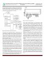
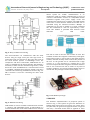
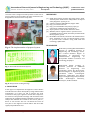
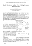
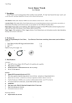
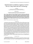
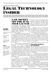
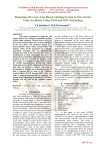
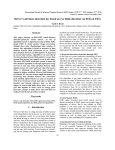
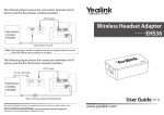
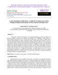
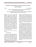
International Research Journal of Engineering and Technology (IRJET)
e-ISSN: 2395 -0056
Volume: 02 Issue: 02 | May-2015
p-ISSN: 2395-0072
ww.irjet.net
DESIGNING OF VCD TO PREVENT TRAIN ACCIDENTS USING GSM AND
GPS TECHNOLOGY
SHAIK.ASHA1 , RPVG.ASHOK REDDY2
PG Student, Department of ECE, Siddharth Institute of Engineering & Technology, A.P, India
Assistant Professor, Department Of ECE, Siddharth Institute of Engineering & Technology, A.P, India
1
2
---------------------------------------------------------------------***--------------------------------------------------------------------2. EXISTING SYSTEM
Abstract - This paper is proposed to design the rail
engines with a new automatic braking system called
Vigilance Control Device (VCD) to prevent the train
accidents. Mostly the train accidents are due to the
unalertness of the loco pilots. This system
microcontroller based alerting system which will keep
the loco pilots in a high alert state by generating
warnings and automatically stopping the train if the
pilot is incapacitated or dead. This paper also gives the
information to the Vigilance Control Officer(VCO)
regarding the position of the train where it is stopped
and position of the loco crew by using Global
Positioning System(GPS) and Global System For Mobile
Communication(GSM) technologies. This system also
stops the train when the loco polit jump the Traffic RED
signal and also informs to higher authority. The system
can display the particular compartment number when
any passenger pulls the chain in Train.
Key Words: ARM7 Micro Controller, VCO, Loco, GSM,
GPS, IR Sensor, Vigilance Warning.
1. INTRODUCTION
In railways, most of the accidents have been caused due to
failure of railway staff. Under optimum field conditions
and with the best of intentions, a human being is likely to
commit a mistake from time to time. This is the reason
why operating conditions include so many redundancies
in safety process and operating rules involve number of
checks and balances. The paper provides a method to
prevent train accidents by alerting the loco pilot cyclically
at regular time intervals. The Vigilance Control Device
(VCD) is an ARM7 Micro Controller based Device which
will automatically apply the penalty breaks in case the
driver is in unalert or dead or fast sleep. This system was
introduced to prevent train accidents, even if the driver
died at his controls, hence the name. Unless a certain
amount of pressure is maintained on the lever, brakes get
automatically activated and the train stops. In this case the
facility to inform the action of the loco pilot and the
position of the train to Vigilance Control Officer to take
any responsible action.
© 2015, IRJET.NET- All Rights Reserved
In existing system is the AT89S52 micro controller based
driver safety system which detects inputs from loco pilot.
It can give continuous warnings to driver alertness; give
emergency braking system and the position of the train to
higher authorities to take action. In this system to ensure
safety to passengers the new automatic braking system is
proposed by using ARM 7 Micro controller. This System
give the continuous time period alerts in cyclic manor, also
can display in which compartment the chain is pulled and
traffic RED signal intimation to the loco pilot, if pilot not
alert automatically train will be stopped and message will
be send to the Vigilance Control Officer (VCO).
3. PROPOSED SYSTEM
In Existing system AT89S52 is used for penalty braking
system. In proposed system we are using ARM7
microcontroller this system developed for automatic
braking system when pilot is in un-alert state, if jump the
traffic Red signal and inform to Vigilance Control
Officer(VCO). The position of the train also sends to the
Vigilance Control Officer by using GSM. AT89S52
microcontroller need more clock cycles compared with
ARM7
microcontroller.
ARM7
having
harward
architecture. ARM7 compiler is more suitable for any
operation it also more efficient in console function.
4. WORKING
This paper consists of following blocks ARM7 controller is
central for all controlling of the Vigilance Control Device
(VCD). The Total Blocks shown in Fig -1. This system
Vigilance Control Device is ARM7 microcontroller based
equipment designed to enhance the safety of the
passengers. This system generates the cyclic warnings to
the loco pilot in throughout the journey. The first
indication to the pilot is Flashing LED, the Second Warning
is Buzzer. If the pilot is not alert/ respond to the warnings,
the VCD can send message to the guard “Driver is not
alert” if the guard apply the brake train will be stop. If the
guard not responds to the message, this system can give
auto brake to the train and train will be stopped. The
“Driver and guard are not alert” message will be send to
the Vigilance Control Office through GSM, by using GPS
train location find out. If the dark night, invisible
conditions the loco pilot can’t see the traffic red signal at
Page 909
International Research Journal of Engineering and Technology (IRJET)
e-ISSN: 2395 -0056
Volume: 02 Issue: 02 | May-2015
p-ISSN: 2395-0072
ww.irjet.net
that situations this system can apply the auto brake when
the RED signal jumped and the message will be send to the
Vigilance Control Officer. If any passenger pulls the chain
in the compartment that particular compartment number
is shown in the LCD display in loco motive.
Fig -2: LCD interfacing diagram
Fig -1: Block Diagram of Proposed System
The input to the proposed system is applied from the
regulated power supply. The A.C input i.e. 230V from the
main supply is step down by the transformer to 12V and is
fed to a bridge rectifier. The output obtained from the
rectifier is D.C voltage from the rectifier is fed to a filter to
remove any A.C components present even after regulation.
Now, this voltage is given to a voltage regulator to obtain a
pure constant DC voltage.
The inputs form the loco pilot are the mechanical inputs,
they are discussed in this paper by using switches. These
inputs are Flashing LED, Horn, Brake, Speed1, Speed2, Red
signal LED, Chain pull in S1, Chain pull in S2 and reset.
MU Mode is multiple unit modes to support the efficiency
of the second engine to the train.
IR Sensor is used to finding the traffic red signal on the
traffic poles. The IR Sensor has the transmitter part and
receiver part. The transmitter part of the sensor project is
an infrared (IR) LED which transmits continuous IR rays
to be received by an IR Receiver. The output of receiver
varies depending upon its reception of IR Rays. Since this
variation cannot be analyzed as such, therefore this output
can be fed to a comparator.
The LCD Display use to Display the messages. LCD screen
is a electronic display module and find a wide range of
applications. A 16*2 LCD means 16 columns and 2 rows
i.e., It can display 16 characters per line and there are 2
lines. The LCD interfacing diagram is shown in Fig -2.
© 2015, IRJET.NET- All Rights Reserved
LEDs (Light Emitting Diodes) are semiconductor light
sources. They are manufactured in different shapes, colors
and sizes. Based on semiconductor diode, LEDs emit
photons when electrons recombine with holes on forward
biasing. The forward voltage of LED(1.7V-2.2V) must be
lower than the voltage supplied(5V) to drive it in a circuit
using an LED as such would burn it because a high current
would destroy its p-n gate. Therefore a current limiting
resistor is used in series with LED. The LED is interfaced
to the output port of microcontroller as the first indication
to alert the loco pilot.
Buzzer is used to alert the loco pilot. The Buzzer is
connected to output port as a second indication to driver.
Buzzer is an audio signaling device, which may be
electronic, mechanical or electro-mechanical that sounds a
warning of continuous or intermittent sound. It produces
high sound pressure levels with minimal from 1 to 30V
whilst sound output may be as high as 75dB at 1m. Buzzer
operates a buzzing noise in the frequency range 300 to
500Hz.
A Relay is an electrically controllable switch widely used
in industrial controls, automobiles and appliances. A relay
is able to control an output circuit of higher power than
the input circuit. Relays are devices which allow low
power circuits to switch a relatively high current/voltage
ON/OFF. For a relay to operate a suitable pull-in & holding
current should be passed through its coil. Generally relay
coils are designed to operate from a particular voltage
often its 5V or 12V. DC (direct current) motors convert
electrical pulses to mechanical movement maximum speed
of DC motor is indicated in RPM. The RPM of a motor is
proportional to the voltage across its terminals. The motor
will sign up in speed until the generator portion of the
motor model matches the supply voltage. At that point no
more current will flow into the motor and it will produce
zero torque. The interfacing of relay and motor is shown in
Fig -3.
Page 910
International Research Journal of Engineering and Technology (IRJET)
e-ISSN: 2395 -0056
Volume: 02 Issue: 02 | May-2015
p-ISSN: 2395-0072
ww.irjet.net
Global system for mobile communication is an
architecture used for mobile communication in most of
countries. GSM module consists of a GSM/GPRS modem
assembled together with power supply circuit and
communication interfaces for computer. The GSM modem
comes with a serial interface which the modem can be
controlled using AT command interface. Multiple at
commands can be sent to modem in a single command
line. The commands in a line are separated by a semicolon. The modem is provided with network status
indication
by
LED
lamp.
Fig -3: Relay and Motor interfacing
The microcontroller can communicate with the serial
devices using its single serial port. The logic levels at
which this serial port operates is TTL logics. But some of
the serial devices operate at RS232logic levels. For
example PC and smart card Reader, GSM Modem etc. In
order to communicate the microcontroller with modem a
mismatch, in other words to match the logic levels, a serial
driver id is used. And MAX 232 is a serial line Driver used
to establish communication between modem and micro
controller. The interfacing of MAX232 is shown in Fig -4. A
DB-9 connector is used for connecting the other serial
devices.
The GPS is used to find out the location of train. The
satellites used for the navigation continuously send signal.
In this GPS receiver is used to pick up the signal from the
satellite, and with the help of this receiver the position of
the user on the ground can be calculated with a high
accuracy. It is very important to consider that a GPS
receiver compares the time of signal transmission with the
time it was received. The GPS is works in any kind of
weather conditions. To track the position Digital maps are
used in GPS. The prototype of GPS is shown in Fig – 5.
Fig -5: GPS Modem prototype
5. RESULTS
Fig -4: MAX232 interfacing
GSM module is used to establish communication between
a computer and GSM-GPRS system. A GSM module is a
wireless modem that works with a GSM wireless network.
© 2015, IRJET.NET- All Rights Reserved
The hardware implementation of proposed system is
shown in Fig -6. The system can give first indication as
flashing LED, if driver does not operate any actions. If the
loco pilot fails, the guard must apply the brake or if guard
also fails, a automatic brake must be applied. In these
Page 911
International Research Journal of Engineering and Technology (IRJET)
e-ISSN: 2395 -0056
Volume: 02 Issue: 02 | May-2015
p-ISSN: 2395-0072
ww.irjet.net
cases the train is stopped and the position of the train is
given to Vigilance Control Officer in terms of latitudes and
Longitudes as shown in below snap shots.
REFERENCES
[1] ITSR, Driver Safety Systems Discussion Paper, 2006,
Australia/New South Wales Independent Transport
Safety Regulator. Sydney, P.32.
[2] GSM user Manual, SIMCOM LTD, August 2006.
[3] http://www.simcom.com
[4] http://www.thehindu.com/todays-paper/tpnational/tp-tamilnadu/article331233.ece
[5] Skytraq Venus 6 GPS module ST22 Data Sheet.
[6] Whitlock, Driver vigilance device: systems review
(and RSSB response) 2002, Rail Safety and Standards
Board/Quintec, p.105.
[7] Ch.Sindhura PG Scholar, Electronics & communication
Dept. “Designing of a low cost based alerting system
to prevent train accidents using GSM and GPS
technology” IJERA 2013.
BIOGRAPHIES
Fig -6: The implementation of proposed system
Fig -7: First indication from the System
Shaik.Asha pursuing Mtech Embedded
Systems in Siddharth Institute of
Engineering and Technology, Puttur.
She received Bachelor Degree in
Department of Electronics and
Communication
Engineering
in
Narayanadri Institute of Science and
Technology, Rajampet.
RPVG.Ashok Reddy working as
Assistant professor in Siddharth
Institute
of
Engineering
and
Technology, Puttur. He Received his
Bachelor Degree in Engineering from
Jawaharlal
Nehru
Technological
University, Hyderabad and Master
Degree in Engineering from Jawaharlal
Nehru
Technological
University,
Anantapur, Andhra Pradesh.
Fig -8: GPS position tracking message
6. CONCLUSION
In this paper we implements the Vigilance Control Device
with IR Sensor has been developed by using GSM and GPS
technologies. It is more use full to prevent the train
accidents. In this paper vigilance control device improves
the alertness and provides warnings and automatic brake
application in predefined manner. With this system we can
analyze that whether the accident is due to loco pilot i.e.,
driver or loco motive. Also we can inform the action of
loco pilot to the Vigilance Control Officer and the traffic
signal jump intimations also.
© 2015, IRJET.NET- All Rights Reserved
Page 912