1
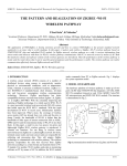
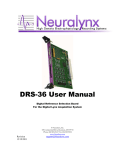
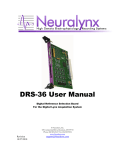
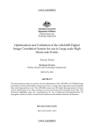
International Journal of Advanced Computer Research (ISSN (print): 2249-7277 ISSN (online): 2277-7970) Volume-2 Number-4 Issue-7 December-2012 Driver’s alertness detection for based on eye blink duration via EOG & EEG Yash S. Desai Student Final Year M.E., Biomedical Engineering Department, Govt. Engineering College, Sector-28, Gandhinagar, India accident may leads towards death also. To prevent this type of threat it is advisable to monitoring driver’s alertness continuously and when we detect condition like pre-drowsy stage or drowsiness driver should be given feedback to be alert. That can act as warning for driver and driver should take enough rest for a time & we can prevent the life threat. Lots of algorithm based on different technique was tested and even implemented for drowsiness detection system. Abstract This paper presents an EEG-EOG based alertness detection system for vehicle drivers. As lots of algorithms based on signal processing of EEG, EOG, facial EMG & facial gesture image processing. Though these have disadvantages that complex in nature. Our algorithm is based on measure of time duration between blink movements of eye. Normal time duration between eye blink patterns is measured by several observations. Algorithm is set such that If the time duration between blink patterns is more than normal than person may napped or not in alert stage. The basic EEG-EOG acquisition system is made and time duration algorithm set through signal processing tool kit in mat lab. Time duration between blink signals crosses the sated reference time that means driver is obviously in abnormal stage maybe in napped or fatigue condition. However both dangerous for driving. We can also design simple hardware, just measuring time duration between two consecutive picks of blink signal which is as same as measure of ECG R to R interval circuit and when we find time duration just beyond reference time we have to trigger on devices that make driver alert or we can give that impulse to device such as energy pulse generator, speaker to make driver alert and that can easily prevent threats of sudden accident. 1. Sleep and drowsiness detection through EEG In this type of system continuous monitoring of brain signal by EEG monitoring system. As EEG can classified into different types of wave like alpha, beta, delta and theta that is respective to activity of brain stage condition and respective frequency. In which alpha wave of 8-13 Hz frequency captured during drowsiness, relaxation type condition. So basic EEG acquisition device can make and frequency based analysis give us person’s stage of drowsiness. [6-8] But algorithm is get huge complexity as we can’t correlate our stage of drowsiness only on EEG wave frequency basis. As alpha wave correlate more than one activity hence we can’t predict about drowsiness on frequency base. So to correlate EEG to find the drowsiness and particularly for driver whose brain activity is change within fraction of second. So it is too complex to set feature extraction algorithm and all that. Keywords 2. Facial muscle EMG EMG signal recorded from facial muscle and by feature extraction of EMG signal can predict stage of fatigueless of driver. But is not reliable as EMG response is not much good for facial muscle with compare to thigh, palm and wrist muscle. And also it can’t always enough noticeable change response under stress condition. In addition it is also hard to conclude tiredness as well as stress only on facial muscle response by also correlating EEG response with it. Driver’s nap detection, EEG-EOG signal processing, EEGEOG signal acquisition, Eye blink pattern reorganization 1. Introduction We know that there is a huge increase of public-private road transportation day by day as we move more steps in the modernize world. As we all know how tedious and bored driving is, when it is for long time distance and time. One of the main causes behind the accident is driver’s unalertness due to long route continues-tedious driving without sleep and rest. Tired Driver losses his alertness and also due to physical cycle of human body can get nap while driving. Even Fraction of second’s nap can be turning into dangerous and lives threaten 3. Duration between eye blink detection Blinking is the rapid closing and opening of the eyelid. It is an essential function of the eye that helps spread tears across and removes irritants from the surface of the cornea and conjunctiva. Blink speed can 93 International Journal of Advanced Computer Research (ISSN (print): 2249-7277 ISSN (online): 2277-7970) Volume-2 Number-4 Issue-7 December-2012 be affected by elements such as fatigue, eye injury, medication, and disease. [1] Generally, between each blink is an interval of 2–10 seconds; actual rates vary by individual averaging around 10 blinks per minute in a laboratory setting. However, when the eyes are focused on an object for an extended period of time, such as when reading, the rate of blinking decreases to about 3 to 4 times per minute. This is the major reason that eyes dry out and become fatigued when reading.[1] It is a myth that women blink nearly twice as much as men. Average male and female blink rates are almost identical, although women using Oral contraceptives blink 32% more often for unknown reasons. Functional anatomy of blinking Blinking provides moisture to the eye by irrigation using tears and a lubricant the eyes secrete. The eyelid provides suction across the eye from the tear duct to the entire eyeball to keep it from drying out. Blinking also protects the eye from irritants. Eyelashes are hairs attached to the upper and lower eyelids that create a line of defence against dust and other elements to the eye. The eyelashes catch most of these irritants before they reach the eyeball. There are multiple muscles that control reflexes of blinking. The main muscles, in the upper eyelid, that control the opening and closing are theorbicularisoculi and levator palpebrae superioris muscle. The orbicularis-oculi closes the eye, while the contraction of the levator palpebrae muscle opens the eye. The Muller’s muscle, or the superior tarsal muscle, in the upper eyelid and the inferior palpebrae muscle in the lower 2 eyelid are responsible for widening the eyes. These muscles are not only imperative in blinking, but they are also important in many other functions such as squinting and winking. The inferior palpebrae muscle is coordinated with the inferior rectus to pull down the lower lid when one looks down. Also, when the eyes move, there is often a blink; the blink is thought to help the eye shift its target point. On this basis our algorithm is formed. We have to measure or monitor the time duration between each blink pattern. When is moves beyond the normal time duration, we conclude that either there is a condition of nap or fatigue. We have to warn driver about that to prevent the accident threats.[8] Central nervous System Control for blink Though one may think that the stimulus triggering blinking is dry or irritated eyes, it is most likely that it is controlled by a "blinking centre" of the globus pallidus of the lenticular nucleus—a body of nerve cells between the base and outer surface of the brain. Nevertheless, external stimuli can contribute. The average length of a blink is 100-400ms. Closures in excess of 1000ms were defined as micro sleeps.[1][2] Greater activation of dopaminergic pathways dopamine production in the striatum is associated with a higher rate of spontaneous eye blinking. Conditions in which there is reduced dopamine availability such as Parkinson's disease have reduced eye blink rate, while conditions in which it is raised such as schizophrenia have an increased rate. We are using basic acquisition system for EEG and EOG signal, and mic port communication to import the signal into computer for signal processing purpose. For this purpose we have to design a system which continuously monitors time between each and every blink patterns. We can get response of eye blink patterns into: EEG EOG Though other signal can also give some response but it may harder than this two. Also facial reorganization by using continuous monitoring of face through image processing gives us enough response and result also but for our task it can be affected by light variation, night vision. And to improve result we have to some addons which is not generally affordable by cost.[8] We observe eye blink response through EEG and EOG and plot the response signal of blink in matlab. We can easily measure the time duration between each blink pattern. 2. Signal Acquisition system for EEG/EOG We are using neuron EEG acquisition setup for acquise the EEG. That gave signal output response into computer. We have to set the electrode position and montages display and computer port setting in it.[7] Any biological must have the following block. Signal Electrodes on body 94 Instrumentation amplifier Filters International Journal of Advanced Computer Research (ISSN (print): 2249-7277 ISSN (online): 2277-7970) Volume-2 Number-4 Issue-7 December-2012 As frequency shift is detects that shows the eye position is shift from open to close or vice versa. Figure 1: Basic block diagram of Signal acquisition As discussed earlier time duration of each blink is 2-10 seconds that only can leads in the diseased or fatigue condition. We set 20second as reference time. If change of shift beyond this time we can say that may person under napped stage or constant eye opened stage. Both conditions are dangerous for driver while driving but first one is more dangerous. Driver gives vocal alert warning to make him alert. In addition we can also give some short of energy pulse also as a addons or as per requirements of system. Surface electrode can use with places electrolytic gel for EOG & metal disc electrodes can be used for EEG.As biological signal lower in amplitude it must be preamplified with help of simple amplifier using operational amplifier so that it can able to drive further circuit. Next we have to amplify signal up to enough level generally in 500milivolt to some short of volt. For EOG signal we are using 0-60 Hz butter worth band pass filter using operational amplifier. For amplifier we set gain of 100 using IC INA2128 and filer circuit gain is 4.Noth filter of 50Hz to filter out the power line noise. Another technique to design this system is manipulation of blink detection through EOG signal which have enough noticeable change response and also have simple acquisition system. [9] Electrode position for EEG For EEG standard unipolar and bipolar 10-20 electrode is generally used. We were used the Ag-AgCl cup electrodes that placed on the scalp according to the international 10-20 system the EEG was recorded from four sites. These bipolar connections were 1) Fz-Oz; 2) C1-C5; 3) C2-C6; 4) 01-02. We are used only instrumentation amplifier and band pass filter further signal conditioning we have done into Matlab software. We have used mic port to transmit the EOG signal. Electrode placement and respective output of signal. We have to use separate circuit for horizontal and vertical movements of EOG.As each type of movements can only seen in respective channel. But blink can be seen into both channels we don’t have two separate circuits. Following section is discussion about the output of response of EOG with respect to terminal of amplifier connected to electrode at particular position. The points chosen for our experimental study were based on two criteria: [3] a) The wide coverage of brain structure: from frontal to central to occipital and also on the both hemispheres. b) Area to be known to produce different types of EEG wave forms such as beta waves from frontal areas and alpha waves from occipital areas. Signal goes positive side followed by negative if eye moves towards respective electrode which is connected to positive terminal of amplifier and it goes negative side followed by positive if eye moves towards respective electrode which is connected to positive terminal. As discussed earlier central nervous system is responsible to control the eye blink detection. We get easily response of change during eye blink. In 1995M.S Ghiyasvand [IEEE-EMBS & 14th BMESI] says that ―The most significant feature of EEG for eye movements is that the any subject the change in peak power frequency was ±6.25 Hz when eyes were opened and closed or vice versa. Therefore this frequency shift has been used to discriminate between the states and generate a trigger command for the prosthesis or any other external device. [3] We are used the same result as a reference and we manipulate the time duration between this frequency shift which is correlate to eye open and close position during blink using simple programme code in matlab. 95 International Journal of Advanced Computer Research (ISSN (print): 2249-7277 ISSN (online): 2277-7970) Volume-2 Number-4 Issue-7 December-2012 Figure 2: Electrode placement and Block diagram for EOG signal acquisition Figure 4: EOG output in respective channel We got the following response of blink movements of eye. Figure 3: Horizontal & vertical channel outputs for right, left, top & bottom side eye movements Figure 5: Continuous Blink detection in Horizontal channel There is no effect have been seen into vertical channel output while eye’s horizontal movements occurs, & vice-versa. 96 International Journal of Advanced Computer Research (ISSN (print): 2249-7277 ISSN (online): 2277-7970) Volume-2 Number-4 Issue-7 December-2012 Figure 6: continuous blink detection in vertical channel 3. Advantages of EOG over other methods The visual systems mentioned above in this section other robust methods of eye tracking, usually with very good accuracy. While in certain circumstances, visual methods may be more appropriate, some of the reasons for favouring the EOG over other options for measuring eye movements are presented here. The EOG typically has a larger range than visual methods, which are constrained, for large vertical rotations where the cornea and iris tend to disappear behind the eyelid. Estimated that since visualization of the eye is not necessary for EOG recordings, angular deviations of up to 80 can be recorded along both the horizontal and vertical planes of rotation using electrooculography. The EOG has the advantage that the signal recorded is the actual eyeball position with respect to the head. Thus for systems designed to measure relative eyeball position to control switches (e.g. looking up, down, left and right could translate to four separate switch presses) head movements will not hinder accurate recording. Devices for restraining the head or sensing head movement are only necessary when the absolute eye position is required. Conversely, visual methods such as the limbus boundary technique require that the head be kept stationary so a head movement will not be misinterpreted as a change in eye position, and even slight head movements with respect to the light source can produce disproportionately large calibration errors. Head-brackets or chin-rests are often used to keep the head in place, often these are uncomfortable and therefore impractical to use for any length of time. Even visual methods that compensate for head movements by tracking relative movement of two points in the eye require that the eyes be kept within the line of sight of the camera and thus often use a head rest any way to keep the head in position. The criterion that the head must be kept in front of a camera may not be possible in certain circumstances where it is conceivable that the user may not be in front of a computer screen or in instances where the user has uncontrolled head spasms, as may be the case for users with cerebral palsy. In visual methods, measurements may be interfered with by scratches on the cornea or by contact lenses. Bifocal glasses and hard contact lenses seem to cause particular problems for these systems. EOG measurements are not affected by these obstacles. EOG based recordings are typically cheaper than visual methods, as they can be made with some relatively inexpensive electrodes, some form of data acquisition card and appropriate software. Any method using infrared light requires an infrared transmitter and camera for operation, plus ex- pensive software to calculate the eye position from the captured image. Software to convert EOG recordings into absolute eye position is considerably more straightforward than video based techniques that require complicated computations to analyse video frames and convert this into an estimate of eye position, and thus EOG software should be less expensive. The EOG is commonly used to record eye movement patterns when the eye is closed, for example during sleep. Visual methods require the eye to remain open to know where the eye is positioned relative to the head, whereas an attenuated version of the EOG signal is still present when the eye is closed. The EOG can be used in real-time as the EOG signal responds instantaneously to a change in eye position and the eye position can be quickly inferred from the change. 4. Limitations of EOG-Based system 97 The EOG recording technique requires electrodes to be placed on both sides of the eyes, and this may cause some problems. Firstly, it requires that a helper is present who has been taught how to correctly position the electrodes.[11] Secondly, electrodes placed around the eyes may draw attention to the user's disability and compromise the user's feelings of dignity. For horizontal EOG recordings, a possible solution is to use a pair of glasses or sunglasses. The two electrodes are placed on the inside of the temple arm of the glasses so International Journal of Advanced Computer Research (ISSN (print): 2249-7277 ISSN (online): 2277-7970) Volume-2 Number-4 Issue-7 December-2012 that the electrodes make contact with the skin when the glasses are worn. Many people who are disabled already wear sunglasses, even indoors, due to photosensitivity. Another large problem faced by EOG-based gaze tracking systems using DC coupled amplifiers is the problem of baseline drift. This problem may be troubleshoot by using an AC coupled amplifier but then the signal recorded will only react changes in the eye position rather than expressing the absolute eye position. If eye position is to be used for any sort of continuous control then a DC coupled amplifier is usually necessary. The measured EOG voltage varies for two reasons. Either the eye moves (which we want to record), or baseline drift occurs (which we want to ignore). Baseline drift occurs due to the following sweating or emotional anxiety pose a more serious problem. Age and Sex: Age and sex have a significant effect on baseline voltage levels, although this should not pose a problem if a system is calibrated initially for each particular user. It's relevant to say that there is also baseline wonder. This phenomenon reveals that is possible detect variations in the offset of the voltage in similar situations. It can be seen that the same person has different baseline potentials. 5. Result and Disadvantage of system We manipulate the signal through matlab programme code and measure the time duration between each blink. If it is beyond the 5 second we can find the unchanged stage that we want. But as if we found time duration between the blink beyond the sated time two conditions may occurs. 1. Driver may at napped stage. (Time duration gets longer time from closed to open eye during blink) 2. Slower rate of blink (Time duration between blink gets longer time from open to close blink!!!) We can use this time duration for feedback purpose to provide warning to driver for alertness as we discussed earlier. factors: Lighting Conditions: The DC level of the EOG signal varies with lighting conditions over long periods of time. When the source of the light entering the eye changes from dark conditions to room lighting, Electrode contact: The baseline may vary due to the spontaneous movement of ions between the skin and the electrode used to pick up the EOG voltage. The mostly commonly used electrode type is silver-silver chloride (Ag-AgCl). Large DC potentials of up to 50mV can develop across a pair of Ag-AgCl electrodes in the absence of any bioelectric event, due to deference in the properties of the two electrode surfaces with respect to the electrolytic Conduction gel. The extent of the ion movement is related to a number of variables including the state of the electrode gel used, variables in the subject's skin and the strength of the contact between the skin and the electrode. Proper preparation of the skin is necessary to maximise conduction between the skin and the conduction gel, usually by brushing the skin with alcohol to remove facial oils. Table 1: Reference time for blink duration measurement and its effectiveness. Time reference 3 seconds 6 seconds 10seconds For sudden napped stage. Effective and useful Not much Effective Not useful Opened eye/slow blink Not useful Not useful May useful Although both condition due to stress and tiredness of driver but first one becomes more dangerous. But when person in the highly concentrate (obviously actively) about the work person’s blink rate is decreased. Same for driver’s conditions & it is not so dangerous with compare to few second’s napped stage. It may irritate for driver to give warning in all the situations. Artefacts due to EMG or Changes in Skin Potential: The baseline signal may change due to interference from other bioelectrical signals in the body, such as the electromyogram (EMG) or the skin potential. EMG activity arises from movement of the muscles close to the eyes, for example if the subject frowns or speaks. These signals may be effectively rejected by careful positioning of the electrodes and through low pass filtering the signal. Skin potential changes due to 6. Conclusion We make final conclusion for our idea to catch driver’s sudden napped stage or unalertness based on measurement of time duration between each blink signal is successful and also low cost in nature and also 98 International Journal of Advanced Computer Research (ISSN (print): 2249-7277 ISSN (online): 2277-7970) Volume-2 Number-4 Issue-7 December-2012 very easy to design. It can works as a boon to driver though this system works in real as if it have a characteristics such as wireless monitoring, more Compaq in size. References [1] JR Taylor , JD Elsworth , MS Lawrence , Sladek JR Jr, Roth RH, Redmond DE Jr.‖ Spontaneous blink rates correlate with dopamine levels in the caudate nucleus of MPTP-treated monkeys‖, 1999 July; 158(1):214-20.‖ PMID: 10448434 [PubMed indexed for medline]. [2] LS Colzato, Van Dn Wildenberg, Van Wouwe, MM Pannebakker, Hommel, B (2009),"Dopamine & inhibitory action control: evidence from spontaneous eye blinkrates" ,www.ncbi.nlm.nih.gov/pmc/articles/PMC2700244 [3] M.S Ghiyasvand, S.K Guha S.Anand and K.K Deepak,‖ A New EEG Signal Processing Technique for Discrimination of Eyes Close and Eyes Open‖ IEEE-EMBS & 14th BMESI – 1995. [4] K. B. Khalifa, M. H. Bedoui, R. Raytchev, and M. Dogui, ―A portable device for alertness detection‖ Proc. Annual Int. IEEE EMBS Special Topic Confe. Microtechnolog. Med. Biol, pp. 584–586, Oct. 2000. [5] K. Van Orden, W. Limbert, S. Makeig, and T. P. Jung, ―Eye activity correlates of workload during a visualspatial memory task,‖Human Factors, vol. 43, no. 1, pp. 111–121, 2001. [6] K. Van Orden, T. P. Jung, and S. Makeig, ―Combined eye activity measures accurately estimate changes in sustained visual driving performance,‖ Biol. Psychol, vol. 52, no. 3, pp. 221–40, 2000. [7] Neurowin verson 6.8,user manual,Nasan Medical Elecronics Pvt.Ltd. [8] Birgitta Thorslund,‖ Electrooculogram Analysis and Development of a System for Defining Stages of Drowsiness‖ VTI särtryck 355A • 2004 Master’s Thesis Project in Biomedical Engineering,Reprint from Linköping University, Dept. Biomedical Engineering. [9] J. Hori, K. Sakano, Y. Saitoh,‖ Development of Communication Supporting Device Controlled by Eye Movements and Voluntary Eye Blink‖ Proceedings of the 26th Annual International Conference of the IEEE EMBS San Francisco, CA, USA • September 1-5, 2004. [10] Ali Bulent Usakli,Serkan Gurkan, ―Design of a Novel Efficient Human–Computer Interface: An Electrooculagram Based Virtual Keyboard‖, IEEE Transactions on Instrumentation and Measurement, VOL. 59, NO. 8, August 2010. [11] Joo Martins, Ana Leal,‖ .Man Machine Interface‖ IAS 2011 - instrumentation and signal acquisition in bioengineering man machine interface. [12] R S Khandpur,‖Handbook of Biomedical Instrumentation‖, twelfth reprint 2008-Tata Mc grew hill company Ltd. Yash S Desai, i was born at the city called the last home of Asiatic lion of Junagadh, Gujarat, India on May 11th 1990.Got secondary education from Carmel convent school, & higher secondary education from Shri D.K.Bharad vidhya mandir, junagadh.Completed B.tech. Biomedical & instrumentation engineering with first class marks from Ganpat University-Mehsana, Gujarat in 2012. Present papar on chemotherapy ports & mind reading with FMRI in national level technical symposiumConvergence 2009 and 2010 respectively, also got 1 st rank in poster presentation competition (poster topic intravascular ultrasound) at convergence-2009 at U.V.Patel College of engineering, Ganpat University Mehsana. Now studying Master of engineering in Department of biomedical engineering at Government Engineering College, Gandhinagar, India. Also works on ―Natural eye movements detection & its application for designing a assist device for paralyzed patients‖ 99