1
Connections
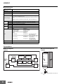
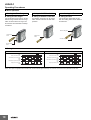
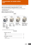
■Block Diagrams
H3DKZ-A1@/A2@
Time specification
switches
Time setting
detection circuit
AC (DC) input
ROM
RAM
Clock
Power supply circuit
Output circuit
One-chip microcomputer
Indicator circuit
Operation/power
indicator
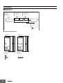
■ Terminal Arrangement
H3DKZ-A1@
H3DKZ-A2@
A1
A1
15
15
25
R1
R1
R2
15
15
25
18
18
16
18
16
A2
16 28
28
26
18
16
26
A2
See note.
See note.
Note: The power supply terminals do not have polarity.
(DIN notation)
A1
A2
4
15
16 18
(DIN notation)
A1
A2
15
25
16 18 26 28