1
H3DKZ-F
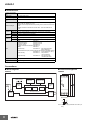
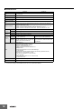
■ Characteristics
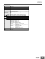
Accuracy of operating
time
±1% of FS max.
Setting error
±5% of FS ±0.05 s max. *
Influence of voltage
±2% of FS max. *
Influence of temperature
±5% of FS max. *
Dielectric strength
Between current-carrying metal parts and exposed non-current-carrying metal
parts: 2,000 VAC 50/60 Hz for 1 min.
Between control output terminals and operating circuit: 2,000 VAC 50/60 Hz for
1 min.
Between contacts not located next to each other: 1,000 VAC 50/60 Hz for
1 min.
Destruction 0.75-mm single amplitude at 10 to 55 Hz for 2 h each in 3 directions
Vibration
resistance Malfunction 0.5-mm single amplitude at 10 to 55 Hz for 10 min each in 3 directions
Shock resistance
Destruction 1,000 m/s2 3 times each in 6 directions
Life expectancy
Mechanical 10 million operations min. (under no load at 1,800 operations/h)
Malfunction 100 m/s2 3 times each in 6 directions
Electrical
100,000 operations min. (5 A at 250 VAC, resistive load at 360 operations/h)
(EMI)
Radiated Emissions:
Emission AC Mains:
Harmonic Current:
Voltage Fluctuations and Flicker:
(EMS)
ESD Immunity:
EMC
EN61812-1
EN 55011 class B
EN 55011 class B
EN 61000-3-2
EN61000-3-3
EN61812-1
EN 61000-4-2: 6 kV contact discharge,
8 kV air discharge
Radiated Radio-Frequency Electromagnetic Field Immunity (AM Radio Waves):
EN 61000-4-3: 10 V/m (80 MHz to 1 GHz)
Burst Immunity:
EN 61000-4-4: 2 kV power line,
1 kV I/O signal line
Surge Immunity:
EN 61000-4-5: 2 kV common mode,
1 kV differential mode
Degree of protection
IP30 (Terminal block: IP20)
Weight
Approx. 110 g
*Actual value.
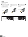
Connections
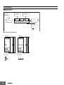
■ Block Diagrams
■ Terminal Arrangement
H3DKZ-F
H3DKZ-F
A1
ON
OFF
indicator indicator
ON/OFF time setting
detection circuit
ON/OFF start switch
15
R1
15
AC (DC)
input
Time
specification
switches
Indicator
circuit
18
ROM
RAM
16
Clock
One-chip microcomputer
Power supply
circuit
Output circuit
18
16
A2
(DIN notation)
A1
A2
15
16 18
Note: The power supply terminals do not have polarity.
8