1
NLSS HD Media Decoder (DC-400, DC-400-2) User Manual © 2009-2012 by Next Level Security Systems, Inc. All rights reserved. Decoder Version 3.0 DC-20120712 NLSS DC400 HD Media Decoder: User Guide DC-20120712 Next Level Security Systems® is a registered trademark of Next Level Security Systems, Inc. NextConnect™ is a trademark of Next Level Security Systems, Inc. All content included in this document, including text, and graphics, is ©2009-2012 Next Level Security Systems, with all rights reserved, or is the property of Next Level Security Systems and/or third parties protected by intellectual property rights. Any use of materials in this document, including reproduction for purposes other than those noted above, modification, distribution, or replication, or other commercial exploitation of any kind, without prior written permission of an authorized officer of Next Level Security Systems is strictly prohibited. Next Level Security Systems' trademarks may not be used in connection with any product or service that is not provided by Next Level Security Systems, in any manner that is likely to cause confusion among customers, or in any manner that disparages or discredits Next Level Security Systems. All other trademarks displayed in this document are the trademarks of their respective owners, and constitute neither an endorsement nor a recommendation of those Vendors. In addition, such use of trademarks is not intended to imply, directly or indirectly, that those Vendors endorse or have any affiliation with Next Level Security Systems. © 2009-2012 Next Level Security Systems, Inc. ii NLSS DC400 HD Media Decoder: User Guide DC-20120712 Contents Preface............................................................................................................... 6 Chapter 1: Introduction ............................................................................. 7 KEY FEATURES..................................................................................... 7 EXAMPLE USE CASES.......................................................................... Retail Store ................................................................................ Medium Sized Business ............................................................. Digital Signage ........................................................................... 8 8 8 8 Chapter 2: Installation ................................................................................ 9 PACKING LIST ....................................................................................... 9 SYSTEM REQUIREMENTS ................................................................... 9 INSTALLATION..................................................................................... Install the Security Certificate................................................... Install Cameras ........................................................................ Install NLSS HD Media Decoder .............................................. 10 10 12 12 Chapter 3: Configuration and Operation via a Browser............. 16 LOGGING IN......................................................................................... 16 ABOUT THE NLSS WEB INTERFACE................................................. 17 Search ...................................................................................... 18 CONFIGURE THE DECODER .............................................................. 19 Reboot...................................................................................... 19 Shut Down................................................................................. 20 General Tab ............................................................................. 20 Editing Fields ..........................................................................22 Changing Decoder Settings ............................................. 23 Advanced Tab .......................................................................... 26 CONFIGURE AND MANAGE USERS ................................................... 27 User Parameters ...................................................................... 28 User Actions ............................................................................. 28 Add a New User ............................................................. 28 Delete a User................................................................. 28 Edit User Parameters..............................................................29 CONFIGURE AND MANAGE CAMERAS............................................. 29 Camera Parameters ................................................................. 30 Parameters From the Camera ......................................... 30 Parameters Configured from the Decoder ......................... 31 Editing Cameras Settings.......................................................... 32 Change A Camera’s Name .............................................. 32 © 2009-2012 Next Level Security Systems, Inc. iii NLSS DC400 HD Media Decoder: User Guide DC-20120712 Customize the Camera’s User Name and Password .......... Select Multicast or Unicast .............................................. Enable / Disable Audio.................................................... Refresh a Camera .......................................................... Adding a Camera ........................................................... Delete a Camera ............................................................ 32 32 33 33 33 34 CONFIGURE AND MANAGE STREAMS .............................................. 35 Stream Types ........................................................................... 35 Stream Parameters .................................................................. 36 Stream Actions ......................................................................... 36 Add a Stream................................................................. 37 Upload a File ................................................................. 37 Edit a Stream ................................................................. 37 Convert a Camera to a Stream ...............................................38 Delete a Stream ............................................................. 38 CONFIGURE AND DISPLAY CHANNELS ........................................... 39 Channel Parameters ................................................................ 39 Channel Actions ........................................................................ 40 Add a Channel ............................................................... 40 Edit a Channel ............................................................... 40 Delete a Channel ........................................................... 40 Display a Channel on a Monitor ....................................... 40 CONFIGURE AND DISPLAY VIEWS ................................................... View Parameters ...................................................................... View Actions............................................................................. Add a View .................................................................... Configure a View ............................................................ Delete a View ................................................................ Display a View on a Monitor ............................................ 41 43 44 44 44 44 45 CONFIGURE AND DISPLAY SEQUENCES ........................................ Sequence Parameters ............................................................. Sequence Actions .................................................................... Add a New Sequence ..................................................... Delete a Sequence ......................................................... Configure a Sequence .................................................... Changing a View’s Duration ............................................ Display a Sequence on a Monitor ..................................... 45 45 46 46 46 46 47 47 Chapter 4: Operation with Peripheral Controls ............................. 49 Display a Channel .................................................................... 51 Display a View........................................................................... 52 View Mode .................................................................... 52 Views List ...................................................................... 52 Displaying a View Pane Full Screen ................................. 52 Display a Sequence ................................................................. 52 Adjust Audio ............................................................................. 52 AXIS T8411 JOYSTICK ......................................................................... 53 Attach the Joystick ................................................................... 53 Display a Channel .................................................................... 53 Control a Pan, Tilt Zoom Camera............................................. 53 Manual Control .............................................................. 54 Presets ......................................................................... 54 © 2009-2012 Next Level Security Systems, Inc. iv NLSS DC400 HD Media Decoder: User Guide DC-20120712 KEYPAD................................................................................................. 55 Attach a Keypad ....................................................................... 55 Display a Channel ..................................................................... 56 Display a View.......................................................................... 56 Display a Sequence ................................................................. 56 Display the Active View ............................................................. 57 Views List Browser ................................................................... 57 Displaying a View Pane Full Screen ........................................ 57 Appendix A: Supported Camera Vendors ....................................... 57 Index ................................................................................................................. 58 © 2009-2012 Next Level Security Systems, Inc. v NLSS DC400 HD Media Decoder: User Manual DC-20120712 Preface PURPOSE, SCOPE, AND AUDIENCE OF THIS DOCUMENT This manual provides installation, configuration, and operation instructions for the NLSS HD Media Decoder. Note: This manual covers operations for two NLSS HD Media Decoders: the NLSS DC400 and the DC-400-2. The DC-400-2 can accommodate two HD monitors. Unless otherwise specified, all instructions apply to both the DC-400 and the DC-400-2 The NLSS HD Media Decoder can be installed with NLSS Gateways, as part of a complete NLSS Unified Security Suite. A Gateway can push video to the Decoder. See the NLSS Unified Security Suite: User Manual, which is available on the NLSS web site. The NLSS HD Media Decoder also can be installed without NLSS Gateways as part of an independent video system. This document also refers to the API of the NLSS HD Media Decoder. This API enables software developers to write third party applications that can communicate with the Decoder. For details, see the NLSS DC-400 HD Decoder: API Reference Manual which is also available on the NLSS web site. © 2009-2012 Next Level Security Systems, Inc. 6 NLSS DC400 HD Media Decoder: User Manual DC-20120712 Introduction Chapter 1: Introduction The NLSS HD Media Decoder is an open, 1080p HD Decoder. The device can simultaneously decode up to four high definition (HD) or standard definition (SD) video streams, and display those streams in up to four panes. The NLSS DC 400-2 HD Media Decoder can display video on two HD monitors or televisions. The NLSS HD Media Decoder is primarily intended for viewing live security cameras, but it is also suitable for other video applications. • In Independent Mode, the Decoder can display a variety of video sources. This manual covers this mode. • In NLSS Mode, the Decoder functions as part of a complete NLSS security system. See the NLSS Unified Security Suite: User Manual from the NLSS web site. The NLSS HD Media Decoder is configured and operated via NLSS Web Interface. The interface can be accessed from most browsers via a networked computer, or a mobile device with a Flash-enabled browser. The Decoder can be operated (but not configured) using a remote control and an onscreen display on a monitor attached to the Decoder. The Decoder can be integrated with third party applications via the NLSS Decoder API. 1.1 KEY FEATURES • Decodes live video streams from IP cameras, as well as other video encoders that use the RTSP, RTMP, and HTTP protocols. • Decodes video streams from local files on the Decoder’s hard drive, in support of digital signage. • Decodes up to four simultaneous HD or SD streams using any of these codecs: • – Video codecs: H.264, MJPEG, MPEG4 – Audio codecs: AAC, G.711, G.726 The DC-400-2 supports Dual Monitor Mode. A decoded stream (at 1080p resolution) is output to two HD displays via an HDMI and a DVI-D cable. The DVI-D can be single link, or dual link for higher bandwidth. The DC-400 outputs a stream to a single HD display via an HDMI port. This output stream can include one to four simultaneous input streams in pane configurations of 1x1, 1x2, 2x2, 3x3, and 4x4. The Decoder maintains the aspect ratios of source streams. • Supports the creation and display of custom channels, views, and sequences. © 2009-2012 Next Level Security Systems, Inc. 7 NLSS DC400 HD Media Decoder: User Manual DC-20120712 • Can be integrated with third party systems via the NLSS HD Media Decoder API, as documented in the NLSS DC-400 HD Media Decoder API Reference Manual. • Comes with the NLSS Discovery Utility, which automatically discovers all NLSS devices on the same LAN. • Includes a 250GB hard disk drive for local storage of content. • Can be configured and operated from most browsers: – The following browsers are able to display the NLSS Web Interface: FireFox (3.0+), Internet Explorer (8.0+), Chrome, and Safari (3.0+). – The Flash 11.2 or later plug-in must be installed in your browser. Note: • The computer must be able to ping the Decoder to access it. Can be operated from a remote control. A remote control with batteries is included with the DC-400-2. 1.2 EXAMPLE USE CASES 1.2.1 Retail Store Retail stores and banks, for example, can display live video from public view security cameras, as a way of informing patrons that they are being recorded for security purposes. 1.2.2 Medium Sized Business Medium size businesses such as resorts, casinos, and commercial construction sites can use the NLSS HD Media Decoder to monitor numerous cameras and access doors throughout their properties. 1.2.3 Digital Signage The NLSS HD Media Decoder can display local media files (such as an animated logo or commercial), as well as RTSP streams for video sources outside the Decoder itself. © 2009-2012 Next Level Security Systems, Inc. 8 NLSS DC400 HD Media Decoder: User Manual DC-20120712 Installation Chapter 2: Installation 2.1 PACKING LIST • DC-400-2 Decoder • Power supply; U.S. and EU power cords • Remote Control and batteries • Stand and VESA mount • NLSS Discovery Utility (CD) • NLSS DC-400 HD Media Decoder: Quick Start Guide 2.2 SYSTEM REQUIREMENTS For details on cameras, displays, file types, and codecs supported by the current version of the NLSS HD Media Decoder, see the Supported Device List. To find the current list, search for Supported Device List in the Support > Knowledge Base page of the NLSS web site: http://www.nlss.com/support-kbase.html • Network: The NLSS HD Media Decoder requires a 100/1000 Mb Ethernet connection to a LAN. • Display: The NLSS HD Media Decoder can be attached to any monitor or television that has DVI-D or HDMI inputs. • Cameras and Discovery Protocols: To be auto-discovered by the NLSS HD Media Decoder, IP cameras must be on the same LAN subnet and adhere to one of the following discovery protocols: • • Arecont • Panasonic • Axis • Pelco • Bonjour Zero Config • Sony • UPnP Computer with Web Browser: The interface can be accessed via a browser running on Windows, Linux, Macintosh or Android-based operating systems. To access the web interface, a computer with a supported browser is required: FireFox (3.0 or above), Safari (3.0 or above), Internet Explorer (8.0 or above), Chrome (16.0) or above. The computer must be able to ping the decoder to access it. © 2009-2012 Next Level Security Systems, Inc. 9 NLSS DC400 HD Media Decoder: User Manual DC-20120712 Installation 2.3 INSTALLATION Complete the instructions the following order to install the NLSS HD Media Decoder: 2.3.1 • Install the Security Certificate • Install Cameras • Install NLSS HD Media Decoder Install the Security Certificate The NLSS HD Media Decoder uses the HTTPS protocol for security purposes. The NLSS CA certificate must be installed for your browser. The following instructions only cover installation of the NLSS CA certificate for Internet Explorer (8.0 or above). For other browsers, consult the browser’s help for instructions on manually installing a CA certificate. 1. Open Internet Explorer. 2. Navigate to www.nlss.com/support-download-cert.html, to locate a link to a page where you can download NLSS CA certificates. 3. Click Download NLSS Certificate. 4. Save the certificate file to your desktop. 5. Double-click the certificate file to open the Certificate dialog. 6. In the General tab of the Certificate dialog, select Install Certificate. The Certificate Import Wizard opens. 7. Click Next to display the Certificate Store dialog. © 2009-2012 Next Level Security Systems, Inc. 10 NLSS DC400 HD Media Decoder: User Manual DC-20120712 Installation 8. Select Place all certificates in the following store. 9. Click Browse to display the Select Certificate Store dialog. A list of certificate stores is displayed. 10. Select Trusted Root Certificate Authorities. 11. Click OK. The list is closed. 12. In the Certificate Store dialog, click Next. 13. Click Finish to close the Wizard. 14. If a Security Warning page displayed, click Yes to complete the Certificate installation. © 2009-2012 Next Level Security Systems, Inc. 11 NLSS DC400 HD Media Decoder: User Manual DC-20120712 2.3.2 Installation Install Cameras For ease of discovery, ensure the IP cameras are installed on the network and powered up before installing the NLSS HD Media Decoder on the same network. Note: 2.3.3 For best results, use the same password for all cameras that the decoder will discover. These settings are set changed locally at the camera, and then entered in the decoder to provide access. See Set Global User Names and Passwords for more information. Install NLSS HD Media Decoder 1. Using an HDMI or DVI-D cable, connect the NLSS HD Media Decoder to the HDMI or DVI-D port of a 1080p monitor. – Use the other video port to connect a second monitor to the NLSS HD DC-400-2 Media Decoder. 2. Connect the NLSS HD Media Decoder to the network shared by your IP cameras. 3. Plug the power adapter into the NLSS HD Media Decoder and then into an AC outlet. 4. Turn on the decoder using the power switch on the front of the device. 5. Insert the supplied NLSS Discovery Utility CD into the disc drive of a computer on the same network as the Decoder. Important: The NLSS Discovery Utility requires Windows, XP or a later, with Microsoft .NET 2.0 or above installed. 6. Copy the Utility file from the CD to the computer’s hard drive. 7. Run the Utility. The Utility lists all the NLSS HD Media Decoders it discovers. 8. In the Utility screen, click Scan to find the NLSS HD Media Decoders on your network. The Utility scans your network and finds all physically attached decoders. In the Utility list of discovered decoders, note the MAC address of the target decoder. Locate your Decoder and note its MAC address © 2009-2012 Next Level Security Systems, Inc. 12 NLSS DC400 HD Media Decoder: User Manual DC-20120712 Installation 9. Enter the decoder’s MAC address in your browser: https://nlss-dc400-macaddress.local where macaddress is the MAC address of the target decoder. For example, if the MAC address of the decoder is 90:E6:BA:B2:F7:C8, then the following URL is entered, with the colons removed from the MAC address: https://nlss-dc400-90e6bab2f7c8.local Note: The scan results of the NLSS Discovery Utility provides both the IP and MAC addresses of the decoder. The IP address can be used to navigate to the decoder, but some issues can occur: » If the NLSS CA certificate is not properly installed, a certificate error is displayed. If so, bypass the error and continue to the decoder. » If the decoder is installed on a network using DHCP, the IP address may change without warning. A bookmark to the decoder using an IP address becomes invalid. A static IP address can be set instead of DHCP. Verify the IP address configuration with the Network Administrator. Since the decoder’s MAC address does not change, bookmarking the URL with the MAC address is the recommended method. 10. Accept requests to install plug-ins and other options, if any. – Bypass certificate errors, if any. Note: After the decoder is installed, any computer with Internet access can access the decoder via the web interface. » The computer must be able to see the decoder. Ping the IP address of the decoder from the computer to verify connectivity. In many networks, connectivity requires that the computer and decoder be on the same network » The computer must have a supported browser installed. A specific operating system is not required to use the web interface, only a supported browser. The decoder’s NLSS Web Interface login screen is displayed. 11. Log into the NLSS HD Media Decoder using the default username and password: – User Name: superuser – Pass: superuser A blank NLSS Decoder Web Interface home page is displayed. The options are selected using the menu at the top of the page, and the remote on the right. © 2009-2012 Next Level Security Systems, Inc. 13 NLSS DC400 HD Media Decoder: User Manual DC-20120712 Installation 12. After logging into the NLSS HD Media Decoder for the first time: a. Customize the default passwords for the Superuser, Admin, and Operator. See Configure and Manage Users for instructions. b. Select Decoder in the Main Menu to display the Decoder page. c. Click the Check Update button to inquire if new firmware is available for the Decoder. If an update is available, update the firmware to the latest version. See Upload and Update Firmware for instructions. – Set the Global Password to match the global password, if one has been set for all of the cameras. See Set Global User Names and Passwords for instructions. – Reboot the decoder and log in again. © 2009-2012 Next Level Security Systems, Inc. 14 NLSS DC400 HD Media Decoder: User Manual DC-20120712 Installation After completing the installation, the decoder can be configured and placed into operation: • Discover all compatible cameras on your network. • List these cameras in the Cameras menu of the NLSS Web Interface. • Create a separate channel for each camera the Decoder can read, and create a 1x1 View for each Channel. • Create one channel containing the NLSS logo video, and display this Channel on an attached monitor. © 2009-2012 Next Level Security Systems, Inc. 15 NLSS DC400 HD Media Decoder: User Manual DC-20120712 Chapter 3: Configuration and Operation via a Browser After installing the NLSS HD Decoder, use a supported web browser to configure and operate the device. See Key Features for a list of supported browsers. 3.1 LOGGING IN These log in instructions presume installation is complete. Note: If this is the first time the NLSS HD Media Decoder is being accessed via the NLSS Web Interface, refer to Installation for the steps to complete installation. 1. Enter the decoder’s URL in a supported browser. This URL can use either the decoder’s MAC address or numerical IP address. See Install NLSS HD Media Decoder. The login screen is displayed for the decoder’s NLSS Web Interface. Note: If the login screen is not displayed, verify the correct MAC address or IP address is entered in the URL. See Install NLSS HD Media Decoder for instructions on running the NLSS Scan Utility to discover the decoder’s IP and MAC addresses. If the URL is correct, ping the decoder to ensure network visibility. 2. In the NLSS Web Interface login screen, access the NLSS HD Media Decoder using a configured user name and password. If the default user names and passwords have not been changed, use the following: • User Name: superuser • Password: superuser © 2009-2012 Next Level Security Systems, Inc. 16 NLSS DC400 HD Media Decoder: User Manual DC-20120712 Configuration and Operation via a Browser 3.2 ABOUT THE NLSS WEB INTERFACE After you log in, the decoder’s Main Menu is displayed with configuration and operations options. Note: The decoder also can be operated from the remote control. See the DC-400-2 remote control diagram in Remote Control Operation in Chapter 4: Operation with Peripheral Controls for more information. The NLSS Web Interface provides a series of menus: • Decoder: Provides hardware-related options for this NLSS HD Media Decoder. See Configure the Decoder for more information. • User: Lists the authorized users of this Decoder. These users can be managed from this pane. See Configure and Manage Users for instructions. • Cameras: Lists all IP cameras discovered on the LAN, and allows some configuration. See Configure and Manage Cameras for instructions. • Streams: Lists all the non-camera video streams that have been configured on this Decoder. Streams can be added, removed, and configured from this pane. See Configure and Manage Streams for instructions. • Channels: Lists all the channels configured for this Decoder. Channels can be added, removed, configured, and displayed from this screen. See Configure and Display Channels for instructions. • Views: Lists all the views configured for this Decoder. Views can be added, removed, configured, and displayed from this screen. See Configure and Display Views for instructions. • Sequences: Lists all the sequences configured for this Decoder. Sequences can be added, removed, configured, and displayed from this screen. See Configure and Display Sequences for instructions. © 2009-2012 Next Level Security Systems, Inc. 17 NLSS DC400 HD Media Decoder: User Manual DC-20120712 • 3.2.1 Configuration and Operation via a Browser Logoff: Ends the NLSS Web Interface session with this Decoder. The decoder can be controlled with the remote control after a user has logged off. See Remote Control Operation for instructions. Search With the exceptions of the Decoder and Logoff menus, all menus include a Search field. In any menu with a search field, entering a text expression in the search field filters out all items in the list with names that do not contain your expression. Example: If the names of all cameras on the second floor of the North Tower include the unique term NT_Floor2, then searching for this term in the Cameras menu updates the list of cameras to show only those on the 2nd floor of the North Tower. Search provides filtering to simplify navigation of a list in an extensive system containing hundreds of cameras, if each is configured according to a naming convention that identifies its location, type, etc. © 2009-2012 Next Level Security Systems, Inc. 18 NLSS DC400 HD Media Decoder: User Manual DC-20120712 Configuration and Operation via a Browser 3.3 CONFIGURE THE DECODER Each NLSS HD Media Decoder can be configured the Decoder page in the NLSS Web Interface session. • Click Decoder from the Main Menu to display the decoder configuration options and parameters. The Decoder page is displayed with two tabs: General and Advanced. Three buttons are available on both tabs: Shutdown, Reboot, Save. 3.3.1 Reboot If the decoder needs to be rebooted, those actions can be done from the Decoder page. 1. Click Decoder in the Main Menu. 2. Click Reboot. The decoder reboots down after confirmation. Note: If any parameters are changed in the Decoder page and a reboot is needed, a prompt is displayed to immediately reboot the decoder after Save is clicked. A manual reboot is not needed. © 2009-2012 Next Level Security Systems, Inc. 19 NLSS DC400 HD Media Decoder: User Manual DC-20120712 3.3.2 Configuration and Operation via a Browser Shut Down If the decoder needs to be shut down, use the Web Interface to properly power off the unit. 1. Click Decoder in the Main Menu. 2. Click Shut Down. The decoder reboots or shuts down after confirmation. Important: Do not use the power button on the decoder or a remote to shut down the unit. 3.3.3 General Tab When Decoder is selected in the Decoder menu, options and a list of parameters are displayed. Some fields are read-only, while others can be edited. • If a parameter is changed, click Save to keep your changes. Important: The decoder reboots automatically, after accepting a confirmation warning. • Model: This decoder model. • Total Disk (GB): The total space (used and free) of the hard drive of the decoder. • Free Disk (GB): The free disk space on the hard drive of the decoder. • Firmware Version: The version number of the currently installed firmware. • Display Width: The width (in pixels) of the display for the output stream. The default setting is 1920 pixels. • Display Height: The height (in pixels) of the display for the output stream. The default setting is 1080 pixels. • Decoder Name: An editable name assigned this decoder. • Global User Name/Password: If use default is checked, the decoder connects to the IP cameras using the camera’s factory default user name and password. See Appendix A: Supported Camera Vendors for more information. If the factory default user name or password has been changed on a camera, complete one of the following steps to allow the decoder to connect to the camera: – Select a custom override for this specific camera. See Customize the Camera’s User Name and Password for instructions. – Configure all source cameras to use the same username and/or password. See Set Global User Names and Passwords for instructions. • Use DHCP: Checked if DHCP is used to provide an IP address to the decoder. • IP Address: If DHCP is disabled, the decoder’s static Internet address is entered. • Subnet Mask: If DHCP is disabled, the subnet mask is entered for selected decoder. • Default IP Gateway: If DHCP must be disabled, the IP address is entered for the network gateway or router. © 2009-2012 Next Level Security Systems, Inc. 20 NLSS DC400 HD Media Decoder: User Manual DC-20120712 Note: Configuration and Operation via a Browser The Default Gateway is a network device, not an NLSS Gateway. • Primary DNS: If DHCP must be disabled, this field sets the IP address for the network’s DNS server. • Enable SSH: When SSH is enabled, qualified technical support staff can remotely access and troubleshoot the decoder using its SSH username and password. When finished, SSH can be disabled to prevent further access. Note: Only superusers have permission to enable SSH. When SSH is disabled, no one can log into the decoder via SSH, even if the correct SSH user name and password are entered. • Disable OSD: If left unchecked, information on a video stream is displayed as an OnScreen Display overlay for a few seconds whenever a channel is switched. This field is unchecked by default. If checked, the On-Screen Display information is not displayed. • Disable Discovery: If checked, the decoder cannot discover any cameras. Note: If the decoder discovered cameras before Disable Discovery was checked, any or all of these cameras can be deleted via the Cameras Menu. Those cameras are not re-discovered as long as Disable Discovery remains enabled. When a decoder is rebooted, camera discovery runs if Disable Discovery is not checked. • Discover Cameras: Click Discover Cameras to locate the supported cameras on the same network as the decoder. • Dual Monitor Mode: This mode applies only to the DC-400-2. Two monitors can be attached to the decoder, one to the HDMI port, and one to the DVI-D port. The arrangement of the display can be configured with two monitors attached to the decoder. The drop-down menu provides five options. – Single Monitor: one monitor is attached to the decoder, using either the HDMI or the DVI-D port. – Dual Horizontal: the current view is spread across two monitors that are installed in a side-by-side configuration. – Dual Horizontal Swap: exchanges the streams between side-by -side monitors. – Dual Vertical: the current view is spread across two monitors that are installed with one monitor above the other. – Dual Vertical Swap: exchanges the streams between monitors that are installed with one monitor above the other. – Clone: sends the same view to both monitors. © 2009-2012 Next Level Security Systems, Inc. 21 NLSS DC400 HD Media Decoder: User Manual DC-20120712 Configuration and Operation via a Browser 3.3.3.1 EDITING FIELDS • Change the Name of the Decoder • Set Global User Names and Passwords • Customize Network Settings 3.3.3.1.1 Change the Name of the Decoder 1. Enter a new name in the Decoder Name field on the Decoder page. 2. Click Save to record your changes. 3.3.3.1.2 Set Global User Names and Passwords The decoder locates the IP cameras on the network the first time it runs. The decoder can access the output of these cameras’ only if the decoder has the correct user names and passwords to access the cameras. Note: If any camera uses unsupported drivers or codecs, then the decoder can connect to these cameras by treating them as remote RTSP streams rather than cameras. See Convert a Camera to a Stream for instructions. Each manufacturer generally uses the same user name and password for their entire line of cameras. If the factory default user names and passwords have been changed on any cameras, then the decoder cannot access their configurations or video streams, even though it detects the camera on the network. The cameras can be configured to use custom user names and/or passwords that override global values. See Customize the Camera’s User Name and Password for instructions. Another option is to configure all cameras to use the same global user name and/or password. Important: The global user name and password overwrite the individual camera passwords. Configure global settings before configuring individual camera settings. 1. Manually configure the camera hardware to use the same user name and password. 2. Open the Decoder page in NLSS Decoder Web Interface. 3. De-select Use Default for the Global User Name parameter. 4. Enter the new user name from Step 1 in the Global User Name field. Note: Depending on the installation, a custom global user name can be used with a factory default password, or vice versa. 5. Repeat Step 5 for the Global Password parameter. 6. Click Save to keep the changes. © 2009-2012 Next Level Security Systems, Inc. 22 NLSS DC400 HD Media Decoder: User Manual DC-20120712 Configuration and Operation via a Browser 3.3.3.1.3 Customize Network Settings The IP Address, Subnet Mask, Default Gateway, and Primary DNS are configured automatically when DHCP is enabled. If DHCP is disabled, then these parameters must be manually entered. The network administrator can provide these parameters. Note: The Default Gateway is the gateway for the network, not an NLSS Gateway. 3.3.3.2 CHANGING DECODER SETTINGS Besides the fields, the Decoder page also contains a series of options for updating, backing up, and restoring the decoder: Firmware Update • Upload and Update Firmware Configuration Restore • Upload Config and Restore Config Administration • Factory Reset • Check Update • Download Logs • Backup Config 3.3.3.2.1 Upload and Update Firmware The decoder’s firmware can be updated manually. Firmware updates can be downloaded to a separate machine and manually applied to the decoder. Note: To automatically update the decoder use Check Update. 1. Contact an NLSS authorized representative to get the latest decoder firmware file. 2. Copy the decoder firmware file to a drive on the same network as the decoder. 3. Open the Decoder page in NLSS Decoder Web Interface. 4. Click Upload Firmware under Firmware Update. The File Upload dialog is displayed. a. Click Browse to locate the new firmware file. b. Click Upload to copy the file to the decoder. 5. Click Update Firmware to install the new firmware using the local firmware file just uploaded to the decoder. 6. Click Yes in the confirmation pop-up. © 2009-2012 Next Level Security Systems, Inc. 23 NLSS DC400 HD Media Decoder: User Manual DC-20120712 Configuration and Operation via a Browser 3.3.3.2.2 Upload Config and Restore Config If a Decoder is replaced or a Factory Reset is run, configuration settings can be restored using the config.zip file created in Backup Config. First, upload the config.zip file created in Backup Config then restore the configuration from these settings. 1. Click Upload Config under Configuration Restore in the Decoder page. 2. Browse to the config.zip file using the file upload dialog. 3. Click Upload to load the configuration backup file to the decoder. 4. Click Restore Config. 5. Click Yes in the confirmation pop-up. Important: Any configuration changes made since the config.zip file was created are overwritten. 6. Click Yes in the confirmation pop-up to allow the decoder to reboot and apply the changes. 3.3.3.2.3 Factory Reset The NLSS HD Media Decoder can be restored to its factory state. The Factory Reset option deletes all files and configurations that the decoder recorded since it left the factory. Note: Firmware updates applied since the decoder was installed are kept. Important: After doing a Factory Reset, the decoder must be installed on the network as though is was being installed for the first time. See Install NLSS HD Media Decoder for instructions. To restore a Decoder to its factory state: 1. Click Factory Reset under Administration on the Decoder page. 2. Click Yes in the confirmation pop-up. The decoder is rebooted during the reset process. © 2009-2012 Next Level Security Systems, Inc. 24 NLSS DC400 HD Media Decoder: User Manual DC-20120712 Configuration and Operation via a Browser 3.3.3.2.4 Check Update Check Update checks with NLSS for a newer version of the firmware, and automatically downloads it, if a newer version is available. • Click Check Update under Administration on the Decoder page. This option automatically updates the decoder’s firmware. Note: If a newer version of the firmware is not available, then Check Update exits without make changes. If new firmware is available, it is installed after confirming the update. The decoder automatically reboots after the installation is complete. This process may take a few minutes. 3.3.3.2.5 Download Logs When contacting NLSS or its authorized representatives for support, a technician might request the decoder’s logs to help with troubleshooting. 1. Select Download Logs in the Decoder page’s Administration button list. 2. Save the decoder’s log file locally. The file can be sent to the support technician via email, FTP, etc. 3.3.3.2.6 Backup Config Configurations of cameras, streams, views, and other items can be backed up on the NLSS HD Media Decoder. A backup is also needed before running a Factory Reset, or Upload Config and Restore Config. 1. Click Backup Config in the Decoder page’s Administration button list. A dialog requests a location to save the config.zip file containing the configurations. 2. Save the config.zip file to the desired location. © 2009-2012 Next Level Security Systems, Inc. 25 NLSS DC400 HD Media Decoder: User Manual DC-20120712 3.3.4 Configuration and Operation via a Browser Advanced Tab The Advanced tab provides four additional configuration settings available from dropdown menus. • Orientation: from the drop-down menu, select an orientation for the monitor attached to the decoder. The correct orientation is when up in the video stream corresponds to the physical top of your monitor in its intended position: – Normal: for monitors positioned horizontally, with no rotation. – Rotate Right: for monitors rotated counterclockwise into a vertical position. When the monitor is rotated left, the video stream is rotated right to compensate. – Rotate Left: for monitors rotated clockwise into a vertical position. When the monitor is rotated right, the video stream is rotated left to compensate. – Flip: for monitors rotated 180-degrees. • Custom Video Settings: identify the type of monitor attached to the decoder. By default, the decoder detects the type of monitor. If it does not detect the monitor, select a model from the drop-down list. • Video Loss Timeout (sec): the length of time the decoder waits before indicating a signal is lost, from 0.5 to 8 seconds. © 2009-2012 Next Level Security Systems, Inc. 26 NLSS DC400 HD Media Decoder: User Manual DC-20120712 Configuration and Operation via a Browser 3.4 CONFIGURE AND MANAGE USERS Users of the decoder are managed from the User page. 1. Click User in the Main Menu. 2. Select a user from the list or Add a New User. User Name, Password, and Type can be edited on the User page. Users also can be added and deleted. By default, the NLSS HD Media Decoder includes three user types: SuperUser, Administrator, and Operator account. Each user type has specific abilities: • SuperUser: Has full control over the decoder. – Default User Name: superuser – Default Password: superuser Note: • • The default SuperUser cannot be deleted, but the name and password can be edited. Administrator: Can run all operations except add, delete, and edit users. – Default User Name: admin – Default Password: admin Operator: Has read-only access to most menus. Can display any Channel, View, and Sequence that is already configured. Can only add, delete, or edit the numbers and names of existing channels, and the names of existing Views and Sequences. – Default User Name: operator – Default Password: operator © 2009-2012 Next Level Security Systems, Inc. 27 NLSS DC400 HD Media Decoder: User Manual DC-20120712 3.4.1 Configuration and Operation via a Browser User Parameters When you select a specific user from the User menu, the following parameters are displayed: 3.4.2 • User Name: The login name for this user. • User Type: Must be SuperUser, Administrator, or Operator. • User Password: (in Edit mode only) The login password for this user. User Actions You must be logged in as a SuperUser to perform the following actions: • Add a New User • Delete a User • Edit User Parameters 3.4.2.1 ADD A NEW USER 1. Click Add above the list of users to display the Add/Edit User screen. 2. Enter a User Name in Add User fields. 3. Enter a User Password twice. 4. Select the Type of user from the drop-down menu. 5. Click Save to keep your changes. – Click Cancel to discard the changes. 3.4.2.2 DELETE A USER 1. Select a user in the Users list. 2. Click Delete above the list. 3. Click Yes in the confirmation pop-up. Note: Users are backed up in the config.zip file if one is accidently deleted. © 2009-2012 Next Level Security Systems, Inc. 28 NLSS DC400 HD Media Decoder: User Manual DC-20120712 Configuration and Operation via a Browser 3.4.2.3 EDIT USER PARAMETERS 1. Select a user in the Users list. 2. Click Edit in the lower right corner of the Users page. 3. Edit the User Parameters. 4. Click Save to keep your changes. – Click Cancel to discard the changes. 3.5 CONFIGURE AND MANAGE CAMERAS Upon installation, the NLSS HD Media Decoder searches for IP cameras on the same network, and connects to the cameras it discovers. Cameras that are on other subnetworks that are not discovered can be manually added. Note: The decoder does not change any settings on the cameras. Rather, the cameras provide the decoder with most of the parameters needed for configuration. 1. Click Cameras in the Main Menu. The Cameras page opens with a list of discovered cameras. The list is searchable. Cameras parameters can be viewed, and cameras can be added and deleted from the list. 2. Select camera from the list to display its settings. 3. Most settings are gathered from the camera and are read-only. See Editing Cameras Settings for editable parameters. If the decoder sees a camera, but cannot read its configuration or video stream, then the camera’s name is preceded by XX in the Cameras Menu. © 2009-2012 Next Level Security Systems, Inc. 29 NLSS DC400 HD Media Decoder: User Manual DC-20120712 Configuration and Operation via a Browser If a camera is on the network and functioning, and the decoder cannot access it: • The user names and/or passwords of the camera may have been changed from the default settings. Two options are available: – Set Global User Names and Passwords ࣣ or ࣣ – Customize the Camera’s User Name and Password. • The camera may use unknown drivers or unsupported codecs. Update the camera’s driver and/or codec. Consult the camera vendor or documentation for more information. • Set up the camera’s video as a remote RTSP stream. See Convert a Camera to a Stream for instructions. The instructions in this section assume that the NLSS HD Media Decoder discovered and fully configured at least one IP camera. For details on cameras, RTSP streams, file types, and codecs supported by the current version of the NLSS HD Media Decoder, see the Supported Device List. To find the current list, search for Supported Device List in the Support > Knowledge Base page of the NLSS web site: www.nlss.com/support-kbase.html 3.5.1 Camera Parameters When a camera is selected from the Cameras Menu, a series of parameters are displayed. Most of the parameters are provided by the camera and are read-only. 3.5.1.1 PARAMETERS FROM THE CAMERA The camera provides following read-only values: • Driver Type: The manufacturer of the camera’s driver. • Firmware Version: The version number of the driver used by the camera. • Model: The model number of the camera. • IP Address: The IP address of the camera. • Video Codec: The video codec used by the camera. The following video codecs are supported: H.264, MJPEG, and MPEG4. • Channel ID: The output channel of the camera. This field is not the same as the Channels used by the decoder. Some cameras can output simultaneously to more than one channel. This parameter indicates to which channel these parameters refer. If a camera has multiple channels, the camera is listed multiple times, one instance for each channel. • Width: The pixel width of the video stream output from the camera. • Height: The pixel height of the video stream output from the camera. • Frame Rate: The frame rate of the video coming from the camera. © 2009-2012 Next Level Security Systems, Inc. 30 NLSS DC400 HD Media Decoder: User Manual DC-20120712 Configuration and Operation via a Browser • Bit Rate: The bit rate of the video stream coming from the camera. • PTZ Cam: Indicates if this camera is capable of pan, tilt, and zoom movements. • Audio Enabled: If the selected camera is capable of audio, this parameter is set to true, and the Audio Codec and Audio Sample Rate parameters are displayed. • Audio Codec: The codec used by the audio track in the stream from the camera. • Audio Sample Rate: The sampling rate of the audio track in the stream from the camera. The decoder supports the following audio codecs: – AAC – G711 A-law and U-law – G726 (40, 32, 24, and 16-kHz sampling rates) Note: If any of the read-only parameters are changed directly on a camera, click Refresh Camera to update these parameters in the NLSS Web Interface. 3.5.1.2 PARAMETERS CONFIGURED FROM THE DECODER The last six parameters are set by the decoder and are editable. • Name: An unique name given to the camera. • User Name: The user name required by the camera to unlock it for streaming. • Password: The password required by the camera to unlock it for streaming. Note: The User Name and Password must match those settings configured directly on the camera. These fields do not change those settings on the camera. • Use Multicast: Check the box to enable multicast. If the box is not checked, unicast is used. • Play Audio: Check the box to allow the decoder to play the camera’s audio, if it is available. If the box is not checked, the camera’s audio is muted on the decoder, regardless of audio capability of the camera. • Orientation: Select an orientation for the camera from the drop-down list. Some cameras rotate the output signals. The decoder cannot automatically determine the rotation of the source stream. This setting sets the decoder to adjust the output for proper viewing. – Normal: The decoder does not rotate the camera stream. – Rotate Right: The decoder rotates the video stream 90-degrees clockwise. – Rotate Left: The decoder rotates the video stream 90-degrees counter-clockwise. – Flip: The decoder rotates the video stream 180-degrees. © 2009-2012 Next Level Security Systems, Inc. 31 NLSS DC400 HD Media Decoder: User Manual DC-20120712 3.5.2 Configuration and Operation via a Browser Editing Cameras Settings • Change A Camera’s Name • Customize the Camera’s User Name and Password • Select Multicast or Unicast • Enable / Disable Audio • Refresh a Camera • Delete a Camera 3.5.2.1 CHANGE A CAMERA’S NAME Camera naming is flexible. 1. Select a camera in the Cameras page. 2. Enter a new Name. 3. Click Save to keep changes. – Click Cancel to discard the changes. 3.5.2.2 CUSTOMIZE THE CAMERA’S USER NAME AND PASSWORD Changing a camera’s automatically configured user name or password overrides the Global Username and Global Password in the Decoder page. See Set Global User Names and Passwords for more information. Important: If the global user name or password are changed, that entry overwrites the local cameras setting. Configure global user names and passwords before configuring individual camera passwords. 1. Select a camera to display its parameters. 2. Enter the User Name and Password required to unlock the camera. 3. Click Save to keep changes. – Click Cancel to discard the changes. 3.5.2.3 SELECT MULTICAST OR UNICAST A multicast camera simultaneously sends the same stream to multiple users. A unicast camera sends a separate stream to each user. 1. Select a camera. 2. Check Use Multicast to enable multicast from the camera. Uncheck the box to enable unicast. Note: The camera must support multicast in order to use it. © 2009-2012 Next Level Security Systems, Inc. 32 NLSS DC400 HD Media Decoder: User Manual DC-20120712 Configuration and Operation via a Browser 3. Click Save to keep changes. – Click Cancel to discard the changes. 3.5.2.4 ENABLE / DISABLE AUDIO The following instructions apply to audio-capable cameras only: 1. Select a camera. 2. Check Play Audio to enable camera’s audio in the decoder. Uncheck the box to disable audio. 3. Click Save to keep changes. – Click Cancel to discard the changes. 3.5.2.5 REFRESH A CAMERA If any parameters are changed locally on a camera, click Refresh Camera to update the information in the Cameras screen. 3.5.2.6 ADDING A CAMERA Cameras not located in the same sub-network as the decoder can be manually added. 1. Click Add above the Cameras list. The New Camera dialog is displayed. 2. Enter a Camera Name. Create a name descriptive of the camera’s physical or network location, or purpose. 3. Select a Driver Type. The Driver Type is dependent on the camera’s manufacturer. The standard ONVIF driver can be selected, if the camera supports it. 4. Enter the Model. This field is optional. 5. Enter the camera’s IP Address. 6. Enter the User Name. If a manufacturer is selected for the Driver Type, check the camera’s documentation for the default setting. If ONVIF is selected, or the user name was changed for the camera, enter the settings entered on the camera. Default manufacturer settings do not apply to ONVIF. 7. Enter and confirm the Password. © 2009-2012 Next Level Security Systems, Inc. 33 NLSS DC400 HD Media Decoder: User Manual DC-20120712 Configuration and Operation via a Browser Ensure the password matches the entry configured directly on the camera, or the manufacturer’s default password, if the setting has not changed. Important: User Name and Password settings are configured on the camera, and not from this interface. The settings entered here must match what is configured directly on the camera. 8. Click Save to keep changes. – Click Cancel to discard the changes. 3.5.2.7 DELETE A CAMERA If a camera is deleted from the Decoder list, then the channel and 1x1 View associated with the camera are deleted automatically. Important: If that 1x1 View is used, then its place in the Sequence remains, with an error message. Manually remove the orphan View from the Sequence. In 1x2 and 2x2 Views, the pane containing the deleted channel shows the NLSS logo animation instead. A different channel can be assigned to that pane. To delete a camera: 1. Select a camera from the Cameras list. 2. Click Delete above the list of discovered cameras. 3. Click Yes in the confirmation pop-up. After a camera has been deleted, the decoder might re-discover it unless it is physically disconnected from the network. The camera is also stored in the config.zip backup file. © 2009-2012 Next Level Security Systems, Inc. 34 NLSS DC400 HD Media Decoder: User Manual DC-20120712 Configuration and Operation via a Browser 3.6 CONFIGURE AND MANAGE STREAMS Video streams are listed in the Streams page. Stream types include local video files, remote RTSP, HTTP, RMTP, and HTTP Stream Source. 1. Click Streams in the Main Menu. 2. Select a stream from the list or Add a Stream. When the decoder is installed, a single file stream with the NLSS logo animation is automatically added to the Streams list. New streams can be added, and existing streams can be edited and deleted from this page. 3.6.1 Stream Types When adding or editing a selection, the parameters are dependent on the Stream Type that is selected from the drop-down list: • RTSP: Select this option for remote streams using to Real-Time Streaming Protocol. • HTTP: Select this option for to access camera that is pushed HTTP. • RTMP: Select this option for remote streams that adhere to the Real-Time Media Protocol. • File: Select this option to play video files (such as logo animations) uploaded to the decoder’s internal hard drive. • HTTP_STREAM: Select this option to access a video file being pushed from a web server or NLSS Gateway, as opposed to uploading the file to the decoder. See the NLSS Unified Security Suite User Manual for more information on pushing video from an NLSS Gateway. © 2009-2012 Next Level Security Systems, Inc. 35 NLSS DC400 HD Media Decoder: User Manual DC-20120712 3.6.2 Configuration and Operation via a Browser Stream Parameters The parameters displayed in the Streams page depend on the type of stream selected. All fields are editable. The parameters for RTSP, RTMP and HTTP streams are the same. Files Streams 3.6.2.0.1 Fields for all streams • Stream Name: An unique name assigned to the stream. When adding an RTSP stream from a camera), include the manufacturers name in the Stream name to activate PTZ capabilities. Supported vendors are Axis, Sony, Panasonic, and ONVIF supported cameras. • Play Audio: Check to enable the audio stream from the camera. Note: Audio takes extra bandwidth. If audio is not needed, disable this parameter to save bandwidth. 3.6.2.0.2 Fields for Internet-based streams • Stream URL: The URL of a local or remote source of the stream. Note: 3.6.3 The URL may require a port number, depending on the video stream source. • Stream UserName: The user name for logging into the source of the stream. • Stream Password: The password for logging into the source of the stream. • Stream Width: The width (in pixels) of the source video stream. • Stream Height: The height (in pixels) of the source video stream. • Use Multicast: Enable for this camera to use multicast; disable to use unicast. Stream Actions • Add a Stream • Delete a Stream • Edit a Stream • Convert a Camera to a Stream © 2009-2012 Next Level Security Systems, Inc. 36 NLSS DC400 HD Media Decoder: User Manual DC-20120712 Configuration and Operation via a Browser 3.6.3.1 ADD A STREAM 1. Click Add above the stream list. 2. Select a Stream Type from the drop-down list. 3. Enter the Stream Parameters. 4. Click Save to keep changes. – Click Cancel to discard the changes. 3.6.3.2 UPLOAD A FILE 1. Click Add above the stream list. 2. Enter a Stream Name. 3. Click Upload File. 4. Browse to a video file on a computer or network location. 5. Upload it to the decoder’s hard drive. 6. Check Play Audio if the file has audio that needs to be played with the video. 7. Click Save to keep changes. – Click Cancel to discard the changes. 3.6.3.3 EDIT A STREAM 1. Select a stream. 2. Edit the Stream Parameters. 3. Click Save to keep changes. – Click Cancel to discard the changes. © 2009-2012 Next Level Security Systems, Inc. 37 NLSS DC400 HD Media Decoder: User Manual DC-20120712 Configuration and Operation via a Browser 3.6.3.4 CONVERT A CAMERA TO A STREAM If the decoder cannot read a camera’s parameters or a video stream, then that camera can be configured as an RTSP stream. 1. Click Add above the stream list. 2. Enter the Stream Parameters for the camera. See Stream Parameters for more information. Note that the Stream URL requires an IP address, a port number and a string, in the following format: rtsp://IPaddress:port/string – where IPaddress is the IP address of the camera – port is the standard RTSP port of 554 – string depends on the camera manufacturer (refer to Supported Camera Vendors). See Appendix A: Supported Camera Vendors for more information on RTSP syntax for specific cameras. 3. Click Save to keep changes. – Click Cancel to discard the changes. 3.6.3.5 DELETE A STREAM 1. Select a stream. 2. Click Delete above the streams list. 3. Click Yes in the confirmation pop-up window. © 2009-2012 Next Level Security Systems, Inc. 38 NLSS DC400 HD Media Decoder: User Manual DC-20120712 Configuration and Operation via a Browser 3.7 CONFIGURE AND DISPLAY CHANNELS When the NLSS HD Media Decoder is installed, channels are automatically created for the NLSS Welcome Animation and all IP cameras that the decoder discovered. Channel assignments can be added and edited from the NLSS Web Interface. Cameras and streams must be assigned a channel before they can be displayed on the monitor attached to the decoder. 1. Click Channels from the Main Menu. 2. Select a channel or Add a Channel. 3.7.1 Channel Parameters Four editable parameters are included with each channel. • Channel Number: A unique number assigned to the current channel. Do not repeat channel numbers in the system. • Channel Name: An editable name for this channel. • Source Type: A drop-down menu that marks the channel as either a Camera or a Stream. • Current Source: A drop-down menu that associates this channel with a selected camera or stream. © 2009-2012 Next Level Security Systems, Inc. 39 NLSS DC400 HD Media Decoder: User Manual DC-20120712 3.7.2 Configuration and Operation via a Browser Channel Actions • Add a Channel • Delete a Channel • Edit a Channel • Display a Channel on a Monitor 3.7.2.1 ADD A CHANNEL 1. Click Add above the Channels list. 2. Enter the Channel Parameters for the new channel. 3. Click Save to keep changes. – Click Cancel to discard the changes. 3.7.2.2 EDIT A CHANNEL 1. Select a channel. 2. Edit the Channel Parameters. 3. Click Save to keep changes. – Click Cancel to discard the changes. 3.7.2.3 DELETE A CHANNEL 1. Select a channel. 2. Click Delete above the channels list. 3. Click Yes in the confirmation pop-up. 3.7.2.4 DISPLAY A CHANNEL ON A MONITOR 1. Select a channel. 2. Click Set Active at the bottom of the screen to display the camera or stream associated with the channel. © 2009-2012 Next Level Security Systems, Inc. 40 NLSS DC400 HD Media Decoder: User Manual DC-20120712 Configuration and Operation via a Browser 3.8 CONFIGURE AND DISPLAY VIEWS A View is an arrangement of panes, each containing channels that can be displayed on the same monitor at the same time. Channels must be assigned to the cameras and streams before being uses in a View. 1. Click Views in the Main Menu. 2. Select a view from the list or Add a View. Views are based on panes. A pane is a rectangular area displaying video from a channel. The layout of a View consists of one or more panes in any of the following arrangements on the screen: • 1x1 • 1x2 horizontal • 2x1 vertical • 2x2 • 3x3 • 4x4 © 2009-2012 Next Level Security Systems, Inc. 41 NLSS DC400 HD Media Decoder: User Manual DC-20120712 Configuration and Operation via a Browser The following examples illustrate some layout configurations: 1x1 (single pane) 1x2 V (two panes arranged vertically) © 2009-2012 Next Level Security Systems, Inc. 1x2 H (two panes arranged horizontally 2x2 (4 panes in a 2x2 arrangement) 42 NLSS DC400 HD Media Decoder: User Manual DC-20120712 3.8.1 Configuration and Operation via a Browser View Parameters When a View is selected from the View Menu, the parameters are displayed. • View Name: An unique name for the view. • Layout Type: Select a layout from this drop-down menu. The Panes graphic reflects the selection. • Panes: (graphic) In conjunction with the Available Channels graphical list, the Panes graphic allows channels to be associated with panes. • Available Channels: (graphic) In conjunction with the Panes graphic, the Available Channels graphic allows channels to be selected for a Pane: – To add a channel to a pane, drag the channel from the Available Channels list to the target pane in the Panes graphic. – To remove a channel from a pane, select the red X in a pane, or drag a new channel to the same pane. New channels overwrite old channels. – To display information on a channel and the camera or other stream it represents, left-click the channel in the Available Channels graphic. © 2009-2012 Next Level Security Systems, Inc. 43 NLSS DC400 HD Media Decoder: User Manual DC-20120712 3.8.2 Configuration and Operation via a Browser View Actions • Add a View • Delete a View • Display a View on a Monitor • Display a View on a Monitor 3.8.2.1 ADD A VIEW 1. Click Add above the View list. 2. Enter the View Name and Layout Type in the View Parameters for the new View. 3. Drag an Available Channel into a Pane. 4. Click Save to keep changes. – Click Cancel to discard the changes. 3.8.2.2 CONFIGURE A VIEW 1. Select a view. 2. Edit the View Parameters. 3. Click Save to keep changes. – Click Cancel to discard the changes. 3.8.2.3 DELETE A VIEW 1. Select a view. 2. Click Delete above the Views list. 3. Click Yes in the confirmation pop-up. © 2009-2012 Next Level Security Systems, Inc. 44 NLSS DC400 HD Media Decoder: User Manual DC-20120712 Configuration and Operation via a Browser 3.8.2.4 DISPLAY A VIEW ON A MONITOR 1. Select a view. 2. Click Set Active to display the View on a monitor attached to the decoder. 3.9 CONFIGURE AND DISPLAY SEQUENCES A sequence consists of two or more views, displayed one after the other in series. Multiple views can be monitored automatically. Only existing views can be used in a sequence. Similarly, only existing channels can be used in views. 3.9.1 Sequence Parameters Each sequence has three editable parameters. • Sequence Name: A unique name that identifies the sequence. • Views: A list of existing views that can be added to the sequence. Click on a view to preview it. • Current Views in Sequence: A list of views used in this sequence. Views can be added, removed, and reordered in the sequence. – • Click on a view in the Current Views list to display its name and duration. Duration: Enter a value (in seconds), and click Set, to define how long each view is displayed before switching to the next view in the sequence. Setting a duration of zero (0) seconds allows video clips to run to completion, regardless of their length. © 2009-2012 Next Level Security Systems, Inc. 45 NLSS DC400 HD Media Decoder: User Manual DC-20120712 3.9.2 Configuration and Operation via a Browser Sequence Actions • Add a New Sequence • Delete a Sequence • Configure a Sequence • Display a Sequence on a Monitor 3.9.2.1 ADD A NEW SEQUENCE 1. Click Add. 2. Configure the Sequence Parameters. 3. Click Save to keep changes. – Click Cancel to discard the changes. 3.9.2.2 DELETE A SEQUENCE 1. Select a sequence. 2. Click Delete. 3. Click Yes in the confirmation pop-up. 3.9.2.3 CONFIGURE A SEQUENCE 1. Select a sequence. 2. Edit the Sequence Parameters. – To add a view to the selected sequence, drag the view from the Views list to the Current Views in Sequence list. – Drag-and-drop the views into the desired order within the list. – To remove a view from the sequence, drag the view out of the list to any blank area on the screen. © 2009-2012 Next Level Security Systems, Inc. 46 NLSS DC400 HD Media Decoder: User Manual DC-20120712 Configuration and Operation via a Browser 3. Click Save to keep changes. – Click Cancel to discard the changes. 3.9.2.4 CHANGING A VIEW’S DURATION After a view is added to a sequence, its duration can be set to be different than the default duration set for the sequence. 1. Click on a view in the Current Views in the Sequence list. The view’s details pane is displayed, showing the view’s name and duration. 2. Enter the Duration, in seconds. 3. Click Save to keep the setting and close the dialog. – Click Cancel (X) to discard the change. 4. Click Save to push changes to the decoder. – Click Cancel to discard the changes. 3.9.2.5 DISPLAY A SEQUENCE ON A MONITOR 1. Select a sequence. 2. Click Set Active to display the sequence on a monitor attached to the decoder. © 2009-2012 Next Level Security Systems, Inc. 47 NLSS DC400 HD Media Decoder: User Manual DC-20120712 Chapter 4: Operation with Peripheral Controls After a Decoder is configured from the NLSS Web Interface, it can be operated with supported peripheral devices: – Remote Control Operation (included with the DC-400-2) – Axis T8411 Joystick – Keypad The joystick and keypad are purchased separately. Important: See the NLSS HD Media Decoder Version 3.0 Supported Devices Technical Bulletin for a list of devices that operate with the decoder. Access this document from the NLSS Knowledge Base at www.nlss.com/supportkbase.html. Note: Selecting a channel, view, or sequence from a peripheral device does not set that item as active. See Chapter 3: Configuration and Operation via a Browser for instructions to enable Set Active through the Web Interface. © 2009-2012 Next Level Security Systems, Inc. 49 NLSS DC400 HD Media Decoder: User Manual DC-20120712 Operation with Peripheral Controls 4.1 REMOTE CONTROL OPERATION Channels must be configured via the NLSS Web Interface, before they can be displayed with the remote control. The remote control model depends on the Decoder model. The remote control was optional with the DC-400, and is included with the DC-400-2. If a remote control is not available, use the on screen remote in the Web Interface to access these functions. DC-400 Remote Control Command (/) View Mode Browser Sequences Browser Views List Channels List Views List OK button and Left / Right Arrows Mute Volume +/- Channel +/- Number Pad © 2009-2012 Next Level Security Systems, Inc. 50 NLSS DC400 HD Media Decoder: User Manual DC-20120712 Operation with Peripheral Controls DC-400-2 remote control is also displayed in the NLSS Web Interface DC-400-2 Remote Control View Mode Browser Sequence Browser Channel List View List OK Up/Down/Left / Right Toggle Volume +/Channel +/- Toggle Mute Command (/) Number Pad 4.1.1 Display a Channel Use the remote control to display existing channels on the monitor attached to the Decoder. Three options are available for selecting channels. • Change channels by using the Channel +/- button. • Enter a channel number with the Number Pad, and press OK. • Press the Channels button to display the Channels List on an attached monitor. i. Use the Left and Right Arrow buttons to select a channel in the list. ii. Press OK button to display the selected channel. iii. Press the Channels button again to close the menu. © 2009-2012 Next Level Security Systems, Inc. 51 NLSS DC400 HD Media Decoder: User Manual DC-20120712 4.1.2 Operation with Peripheral Controls Display a View A view can be displayed from the View Mode or the View List. 4.1.2.1 VIEW MODE View Mode Browser activates a toggle through the views configured on the decoder. 1. Press the View Mode Browser button. 2. Press the Channel +/- button to toggle between views on the monitor. 3. Press the View Mode Browser button again to close the View Mode. 4.1.2.2 VIEWS LIST A view can be selected from an on-screen View List. 1. Press the Views List button to display the Views List on an attached monitor. 2. Use the Left/Right Arrow buttons to select a view in the list. 3. Press OK to display the selected View. 4. Press the View List button again to close the menu. 4.1.2.3 DISPLAYING A VIEW PANE FULL SCREEN A pane in a view can be selected and displayed full screen on an attached monitor. This feature is helpful when adjusting a PTZ camera. 1. Use the Arrow buttons to select a view in the pane. The The selected pane is highlighted by a blue rectangle. 2. Press OK. The pane is now displayed full screen. 3. Press OK again to return to the view. 4.1.3 Display a Sequence 1. Press the Sequences button to display a configured sequences. 2. Press the Sequences button again to display a different sequence. To cancel sequences, select any channel or view from their respective menus. 4.1.4 Adjust Audio • Change volume with the Volume +/- buttons. • Toggle sound on/off with the Mute button. © 2009-2012 Next Level Security Systems, Inc. 52 NLSS DC400 HD Media Decoder: User Manual DC-20120712 Operation with Peripheral Controls 4.2 AXIS T8411 JOYSTICK The joystick can be used alone, or in conjunction with a Keypad, to change channels and move a PTZ (pan-tilt-zoom) camera. The joystick cannot be used to display views and sequences, or to adjust volume. The keypad handles those functions. 4.2.1 Attach the Joystick A joystick can be added and removed at any time. The decoder recognizes the device in about five seconds. • 4.2.2 Plug the Axis T8411 joystick into an open USB slot on the NLSS HD Media Decoder. Display a Channel Each channel corresponds to a video stream from a camera. • 4.2.3 Change channels by using the L and R buttons. Control a Pan, Tilt Zoom Camera The joystick can control a live PTZ camera. The joystick cannot control PTZ functions for a stream, even if the source is PTZ capable. 1. Open the NLSS HD Decoder Web Interface. See Chapter 3: Configuration and Operation via a Browser for more information. 2. Click Cameras in the main menu. 3. Select a camera from the Cameras list. If the camera is PTZ enabled, it can be moved using the joystick or by using presets. © 2009-2012 Next Level Security Systems, Inc. 53 NLSS DC400 HD Media Decoder: User Manual DC-20120712 Operation with Peripheral Controls 4.2.3.1 MANUAL CONTROL • To pan the camera, move the joystick left and right. • To tilt the camera, move the joystick up and down. • To zoom the camera, twist the joystick handle. 4.2.3.2 PRESETS The J1 - J4 buttons call presets for live cameras. These presets must be configured on the source cameras before the joystick can call them. 1. Follow the instructions provided by the camera’s manufacturer to log into the configuration menu of the desired camera. 2. In the camera’s configuration menu, set up the first four camera presets according to the manufacturer’s instructions. Label these presets exactly as follows: – PRESET_1 – PRESET_2 – PRESET_3 – PRESET_4 3. After presets are configured, move the camera to those presets by using the J1 - J4 buttons. For example, to move the camera to PRESET_1, press the J1 button. © 2009-2012 Next Level Security Systems, Inc. 54 NLSS DC400 HD Media Decoder: User Manual DC-20120712 Operation with Peripheral Controls 4.3 KEYPAD A keypad can change the channels configured on the NLSS HD Media Decoder. See Configure and Display Channels in Chapter 3: Configuration and Operation via a Browser for instructions on setting up channels. Only certain keypads are supported by the system, although these keypads all use a standard design. See the NLSS HD Media Decoder Version 3.0 Supported Devices Technical Bulletin for a list of supported keypads. This document is available from the NLSS Knowledge Base at www.nlss.com/support-kbase.html. 4.3.1 Attach a Keypad A keypad can be added and removed at any time. The decoder recognizes the device in about five seconds. • Plug the keypad into an open USB slot on the NLSS HD Media Decoder. The forward slash key (/) acts as a command key that is pressed before entering a number to trigger an action. © 2009-2012 Next Level Security Systems, Inc. 55 NLSS DC400 HD Media Decoder: User Manual DC-20120712 4.3.2 Operation with Peripheral Controls Display a Channel Three options are available to access a channel from a keypad. 4.3.3 • Change the channels using the + and – keys. • Enter a channel number on the Number Pad, and press Enter. • Use the keypad to navigate a Channels list: i. To display a Channels list, enter /1Enter, as follows: a. Turn on Num Lock. b. Press the slash key (/). b. Press the number 1. c. Press Enter. ii. Turn off Num Lock. iii. Navigate the channels list using the Arrow keys (2, 4, 6, and 8 keys with NumLock off) to highlight a channel. iv. Press Enter. Display a View 1. Turn on Num Lock. 2. Type /2Enter, as follows: a. Press the slash key (/). b. Press the number 2. c. Press Enter. 3. Turn off Num Lock. 4. Use the Arrow keys to highlight a view in the Views list. 5. Press Enter. 4.3.4 Display a Sequence 1. Turn on Num Lock. 2. To display a list of sequences, type /3Enter, as follows: a. Press the slash key (/). b. Press the number 3. c. Press Enter. 3. Turn off Num Lock. 4. Use the Arrow keys to navigate the sequences list. 5. Highlight a sequence, and press Enter. © 2009-2012 Next Level Security Systems, Inc. 56 NLSS DC400 HD Media Decoder: User Manual DC-20120712 4.3.5 Operation with Peripheral Controls Display the Active View The Active View is the view last Set Active on the Decoder using the NLSS Web Interface. See Display a View on a Monitor in Configuration and Operation via a Browser for more information. Even if the display is changed with a remote control, joystick, or keypad, channels, or sequences, the Active View remains the same in the decoder’s memory. 1. Turn on Num Lock. 2. Type /4Enter on the keypad: a. Press the slash key (/). b. Press the number 4. c. 4.3.6 Press Enter key. Views List Browser A view can be selected from an on-screen View List. 1. Turn on Num Lock. 2. Type /5Enter on the keypad: a. Press the slash key (/). b. Press the number 5. c. Press Enter key. The Views List is displayed on an attached monitor. 3. Turn off Num Lock. 4. Use the Left/Right Arrow buttons to select a view in the list. 5. Press Enter to display the selected View. 6. Press the slash key (/) again to close the list. 4.3.7 Displaying a View Pane Full Screen When a view is displayed, a selected pane can be expanded to full screen. 1. Turn on Num Lock. 2. Use the arrow keys to select or highlight a view. 3. Press Enter. 4. Press Enter again to return to view. © 2009-2012 Next Level Security Systems, Inc. 57 NLSS DC400 HD Media Decoder: User Manual DC-20120712 Appendix A: Supported Camera Vendors The NLSS HD Media Decoder supports some or all of the IP cameras from the manufacturers listed below. This list includes the default user names, passwords, and RTSP syntax that each manufacturer typically uses for its IP cameras. For exceptions and updates, refer to the documentation provided by the manufacturers of your cameras. Manufacturer Default User Default Password Example RTSP Syntax Arecont Vision admin blank rtsp://10.11.23.50:554/ h264.sdp?res=half&x0=0&y0=0&x1=1920&y1=1200&q p=20&doublescan=0&bitrate=65535&ssn=20 Axis root Must be set rtsp://10.11.22.103:554/mpeg4/media.amp rtsp://10.11.20.138:554/axis-media/media.amp IQInvision root system rtsp://10.11.22.110:554/PSIA/Streaming/channels/0 Panasonic admin 12345 rtsp://10.11.20.112:554/MediaInput/mpeg4 Pelco admin blank rtsp://10.11.23.114:554/stream1 Sony admin admin rtsp://10.11.11.224:554/media/video1 For a list of individual camera models that NLSS supports, see the NLSS HD Media Decoder Version 3.0 Supported Devices Technical Bulletin. This document is available from the NLSS Knowledge Base at: www.nlss.com/support-kbase.html. © 2009-2012 Next Level Security Systems, Inc. 57 NLSS DC400 HD Media Decoder: User Guide DC-20120712 Index A active view selecting with a keypad 57 adding cameras 33 channels 40 sequences 46 streams 37 users 28 views 44 Administrator 27 Advanced tab 26 Custom Video Settings 26 Video Loss Timeout 26 Audio enabled 31 audio camera disable 33 enable 33 codec 31 play camera 31 streams 36 remote control adjustments 52 sample rate 31 Available Channels, views 43 B Backup Config 25 Bit Rate 31 browser supported 9 browsers supported 8 C Camera page adding a camera 33 deleting a camera 34 © 2009-2012 Next Level Security Systems, Inc. cameras adding 33 audio disable 33 enable 33 enabled 31 sample rate 31 audio codec 31 bit rate 31 Channel ID 30 configuring 29 converting to a stream 38 deleting 34 discover 21 editable parameters Name 31 Orientation 31 password 31 Play Audio 31 Use Multicast 31 User Name 31 Firmware Version 30 frame rate 30 installation 12 IP address 30 joystick presets 54 list 29 Model 30 multicast 32 name 31 changing 32 parameters 30 password changing 32 passwords 22 PTZ control with a joystick 53 PTZ indicator 31 refresh 33 unicast 32 user name 22 changing 32 Video Codec 30 video stream height 30 width 30 Cameras page 29 parameters 30 Channel ID 30 58 NLSS DC400 HD Media Decoder: User Guide DC-20120712 Orientation 26 Reboot button 19 Shut Down button 20 Update Firmware 23 Upload Config 24 Upload Firmware 23 Channel Name 39 Channel Number 39 channels adding 40 Channel Name 39 Channel Number 39 configuring 39 current source 39 deleting 40 displaying 40 editing 40 parameters 39 selecting with a joystick 53 selecting with a keypad 56 selecting with a remote control 51 Source Type 39 views 43 Default IP Gateway 20 deleting cameras 34 channels 40 sequences 46 streams 38 users 28 views 44 DHCP 20, 23 Disable Discovery 21 Channels page 39 Disable OSD 21 Check Update 25 discovery cameras 21 disable 21 Clone 21 codecs 7 audio 31 video 30 configuration back up 25 channels 39 Decoder 19 sequences 45, 46 views 41, 44 Display Height 20 Display Width 20 Download Logs 25 downloading logs 25 Driver Type, cameras cameras Driver Type 30 Configuration Restore Upload Config 24 Dual Horizontal 21 configuring video streams 35 Dual Monitor Mode 7 settings 21 Current Source 39 Dual Vertical 21 Current Views in Sequence 45 Dual Vertical Swap 21 Custom Video Settings 26 Duration 45 changing for sequence view 47 D decoder installation 12 URL 16 Decoder Name 20 edit 22 Decoder page 19 Advanced tab 26 Backup Config 25 Check Update 25 Download Logs 25 Factory Reset 24 fields 22 General tab 20 © 2009-2012 Next Level Security Systems, Inc. Dual Horizontal Swap 21 E editing channels 40 streams 37 users 29 Enable SSH 21 F Factory Reset 24 file stream upload 37 59 NLSS DC400 HD Media Decoder: User Guide DC-20120712 streams 35 firmware update (decoder) 23 version cameras 30 decoder 20 Frame Rate cameras 30 Free Disk 20 full screen display 52 G General tab, Decoder page 20 Global Password 20 setting 22 Use Default 22 User Name 20 setting 22 Use Default 22 H hard disk, capacity 8 Height cameras video stream 30 video streams 36 HTTP 35 HTTP_STREAM 35 I installation cameras 12 decoder 12 requirements 9 security certificate 10 IP Address 20 IP address cameras 30 stream URL 38 IP Gateway 20 J joystick 53 installing 53 presets 54 PTZ controls 53 selecting channels 53 © 2009-2012 Next Level Security Systems, Inc. K key features 7 keypad full screen view pane 57 view list 57 keypads 55 active view 57 channel selection 56 installing 55 selecting sequences 56 selecting views 56 L Layout Type 43 log in 13, 16 first time 14 procedure 16 superuser 13, 16 logs, downloading 25 M MAC address 12 Main Menu Decoder 19 User 27 main menu 14 Decoder page 19 introduction 17 options 17 Model, camera 30 monitor displaying channels 40 sequences, displaying 47 views, displaying 45 monitors setting type 26 video loss 26 multicast 32 cameras 31 streams 36 mute 52 N Name channels 39 sequences 45 stream 36 view 43 60 NLSS DC400 HD Media Decoder: User Guide DC-20120712 Name, camera 31 requirements 9 network settings 23 resetting the decoder to factory settings 24 NLSS Discovery Utility 12, 13 RTSP 35 NLSS Web Interface Decoder page 19 introduction 17 S sample rate audio 31 O search function, using 18 On Screen Display 21 Operator 27 security certificate installation 10 Orientation 26 Sequence Name 45 orientation camera 31 sequences adding 46 configuring 45, 46 current views 45 deleting 46 display 47 displaying with a remote control 52 Duration (view) 45 Duration (views) changing 47 parameters 45 selecting with a keypad 56 Sequence Name 45 views 45 Orientation, monitors 26 OSD 21 P packing list 9 Panes 43 password camera 31 cameras changing 32 streams 36 Play Audio cameras 31 streams 36 Sequences page 45 shutting down the decoder 20 Single Monitor 21 Source Type 39 Primary DNS 21 SSH 21 protocols 7 discovery, cameras 9 Stream page 35 PTZ controlling with a joystick 53 PTZ Cam 31 R rebooting the decoder 19 refreshing camera parameters 33 remote control audio adjustment 52 channel selection 51 DC-400 model 50 DC-400-2 model 51 displaying sequences 52 full screen display 52 selecting views 52 views list 52 © 2009-2012 Next Level Security Systems, Inc. Stream URL IP address 38 streams adding 37 configuring 35 converting from a camera 38 deleting 38 editing 37 file upload 37 height 36 name 36 parameters 36 Password 36 Play Audio 36 types file 35 HTTP 35 HTTP_STREAM 35 RTSP 35 URL 36 61 NLSS DC400 HD Media Decoder: User Guide DC-20120712 Use Multicast 36 User Name 36 width 36 adding 28 configuring 27 deleting 28 editing 29 Subnet Mask 20 superuser 13, 16 SuperUser user type 27 system requirements 9 V video custom settings 26 loss 26 T Video Codec 30 total disk space 20 Video Loss Timeout 26 U video streams configuring 35 unicast 32 upload firmware 23 stream file 37 Upload Config 24 URL IP address 16 MAC address 13 Mac address 16 stream 38 streams 36 use cases 8 Use Default 22 Use Multicast cameras 31 streams 36 User Name camera 31 changing 32 streams 36 User page 27 adding a user 28 deleting a user 28 editing users 29 parameters 28 user type defined 27 users © 2009-2012 Next Level Security Systems, Inc. View Mode Browser remote control access 52 View Name 43 views adding 44 Available Channels 43 configuring 41, 44 deleting 44 displaying 45 full screen display 52 full screen panes with keypad 57 in a sequence 45 layout type 43 Name 43 pane layout 41 Panes 43 parameters 43 selecting with a keypad 56, 57 selecting with a remote control 52 sequences 45 Views page 41 volume control 52 W Web Interface introduction 17 Width video stream 30 video streams 36 62
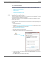
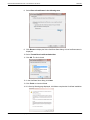
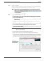
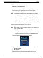
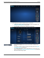
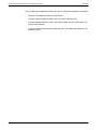
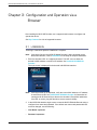
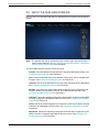
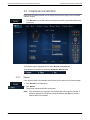

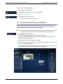
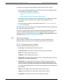
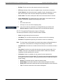
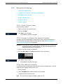
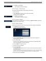
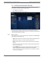
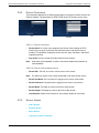
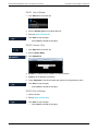
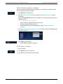
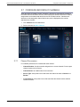
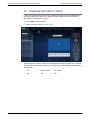
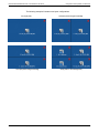
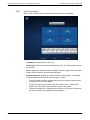
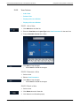
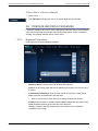
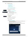
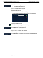
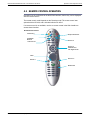
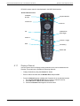
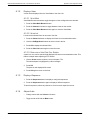
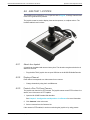
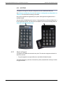
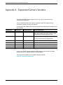
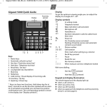


![RessqM, Enhanced Version of RESSQ [Javandel et al., 1984]](http://vs1.manualzilla.com/store/data/005674408_1-e8a4b9f66c80cdc83d847a710e5b4b1f-150x150.png)