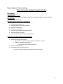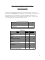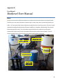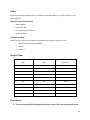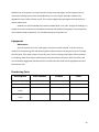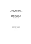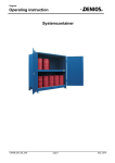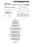
1
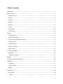
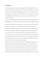
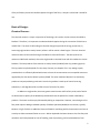
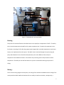
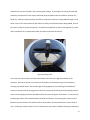
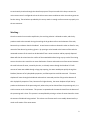
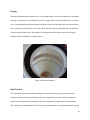
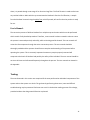
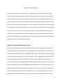
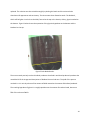
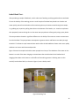
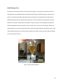
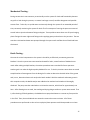
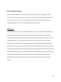
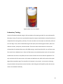
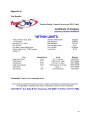
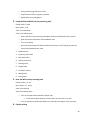
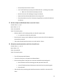
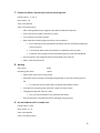
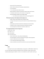
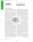
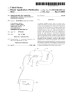
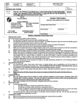
Senior Design Final Report April 16 2009 Oluwatobi Adeyinka, Kyle Baker, Cody Coggins, Luke Ricks, Alex Rodriguez Advisor: Dr. Peter Kelly-Zion Trinity University Biodiesel Initiative Abstract: In the past year it has been the goal of the Trinity University Biodiesel Initiative to design and build a biodiesel processing plant capable of producing B100 biodiesel. The plant and operational information will be handed over to the Physical Plant for continued operation. This report details the design, construction, testing and operation of this processing plant. Table of Contents Introduction .................................................................................................................................................. 4 Basis of Design: ............................................................................................................................................. 5 Chemical Process – ................................................................................................................................... 5 Filtering – .................................................................................................................................................. 6 Heating - .................................................................................................................................................... 7 Mixing –..................................................................................................................................................... 7 Washing –.................................................................................................................................................. 9 Drying – ................................................................................................................................................... 10 Final Product – ........................................................................................................................................ 10 User’s Manual - ....................................................................................................................................... 11 Testing:........................................................................................................................................................ 11 Initial Mixing Test - .................................................................................................................................. 12 Small Scale Mixing Test - ......................................................................................................................... 12 Small Scale (Coke Bottle) Process Test - ................................................................................................. 13 Initial Wash Test - ................................................................................................................................... 15 Initial Drying Test - .................................................................................................................................. 16 Mechanical Testing - ............................................................................................................................... 17 Batch Testing -......................................................................................................................................... 17 Final Testing / Results: ................................................................................................................................ 18 pHLip Test - ............................................................................................................................................ 18 Laboratory Testing - ............................................................................................................................ 19 Budget: ........................................................................................................................................................ 20 Conclusion and Recommendations: ........................................................................................................... 20 Appendix A: ................................................................................................................................................. 22 Test Results - ........................................................................................................................................... 22 Project Schedule - ................................................................................................................................... 23 Budget - ................................................................................................................................................... 25 Appendix B: ................................................................................................................................................. 28 User Manual -.......................................................................................................................................... 28 Safety .................................................................................................................................................. 29 2 Recipe Table ........................................................................................................................................ 29 Procedures .......................................................................................................................................... 29 Usage................................................................................................................................................... 33 Equipment ........................................................................................................................................... 34 Reordering Parts ................................................................................................................................. 34 3 Introduction The overall goal of this project is to convert waste vegetable oil into a usable biodiesel fuel. In order to accomplish this task, biodiesel processing was researched and then implemented into a system to fit our specific needs. The following report describes the design, utilization, and results of the two semester senior design project. Everything incorporated in the design, from the initial transportation and storage of the waste vegetable oil, WVO, through the entire conversion, storage, and implementation of the resultant fuel is discussed. The production of biodiesel begins with an initial filtration of the WVO to remove suspended particles from the feedstock, which is then stored until ready to be processed. The filtered WVO is then prepared to undergo the chemical reaction transesterification to convert stored energy, in the form of free fatty acids, into a more readily usable form. The chemicals utilized in this reaction consist of a catalyst mixture comprised of NaOH dissolved in methanol, which is hazardous. The hazard of using methanol has been addressed with built in safety measures throughout the process and is discussed in further detail in the report. The process creates biodiesel and also the resultant by-products of glycerin and soap. Once the reaction moves to completion, the products settle for a period of time during which the glycerin, being denser than the biodiesel, collects at the bottom of the processing tank. The glycerin can be drained from the bottom of the processing tank and disposed of properly leaving the biodiesel to be further purified through processes known as washing and drying. The washing process consists of misting water, which is denser than biodiesel, over the surface of the biodiesel to capture dissolved impurities through waters adhesive nature. The water pulls all the impurities to bottom of the coned tank where the dirty water is drained from the processing tank. The drying process removes residual water left in the biodiesel from washing. Drying is accomplished by pumping the biodiesel through the system and spraying the biodiesel through a nozzle back into the processing tank allowing it to aerate and removing the water through evaporation. After the completion 4 of the purification process the biodiesel passes through a final filter, a sample is tested and is stored for use. Basis of Design: Chemical Process – The chemical reaction is a major component of the design; this reaction is what converts the WVO to biodiesel. Therefore, it is important to understand what happens during the conversion of WVO into a useable fuel. The waste oil will undergo a chemical change to optimize the energy conversion, by converting triglycerides to methyl esters, before it will be used in a diesel engine. The main chemical reaction that drives the manufacturing the biodiesel is transesterification. The two inputs to the reaction are WVO and methanol, where the triglycerides in the WVO react with the methanol to create biodiesel. The two products of the reaction are methyl esters (biodiesel) and a by-product (glycerin). This by-product may be disposed of in two ways. One way is to dispose of it in city sewage system, provided that it is sufficiently diluted with water to lower the concentration to an acceptable amount as regulated by the San Antonio Water Systems (SAWS). The other method of disposal is to add the byproduct to compost producing earth tubs. Since the by-product is made up of natural occurring substances, it will degrade and be a useful source of nutrients for plants. In addition to triglycerides, the waste grease contains water and free fatty acids, both of which are detrimental to quality of the biodiesel produced and have the potential to create unwanted byproducts. The water can be simply eliminated by boiling or evaporation. However, neutralizing the free fatty acids requires adding a standard quantity of Sodium Hydroxide (NaOH) to the reaction, typically between 3-5 g/L of WVO. An additional amount of NaOH is used along with the base amount and acts as a catalyst to allow transesterification to occur. Sodium Hydroxide has been chosen as the free fatty acid neutralizer and catalyst based on ease of handling, ease of purchasing, and recommendations from 5 other biodiesel producers. The NaOH will be dissolved in the methanol to create a solution called methoxide, which is caustic. This methoxide is then mixed with the WVO, resulting in the reaction. The NaOH used during the process will be provided in the form of flakes. This medium was chosen, as opposed to powder or pellet form, based on the idea that flakes can be handled more easily than powder, and will dissolve more readily than pellets; therefore making the mixing process more effective. Proper precaution when handling these chemicals will be taken, given the nature of the chemicals. These include proper storage, security, and signage, including MSDS sheets, alerting of the dangers associated with chemicals in use. Once the reaction has reached completion, the by-products will separate from the biodiesel, due to the by-products having a higher density, and can then be drained from the bottom of the processing tank. Residual by-product in the biodiesel can then be separated using a water washing method. The entire reaction will occur at a temperature between 110-120°F in order to allow the reaction to occur in an acceptable time frame (1.5-2.5 hours). The topics of mixing, washing, drying, and heating will be discussed later in this report. Filtering – The first step in the preparation of the WVO for processing is the initial filtering to remove any particulates remaining from its use in food preparation, including suspended fat. A 100 micron barrel filter, fitted over the WVO storage barrel, will be used and allow for easy filtration. Waste vegetable oil from the kitchens can be taken directly to the storage barrel and filtered for storage. The filters have a lip that allows the mesh bottom of the filter to reside in the barrel. This design allows for a volume of at least 10 gallons to be poured into the filter at once, as it is filtered into the storage barrel. The volume of WVO contained by the filter is beneficial because the head pressure created results in faster filtration. 6 ← Catalyst Tank Processing Tank → ↑ Drum Heater Storage Barrel → In-line Heater ↓ Figure 1 TUBI Biodiesel Processing System Heating The process of transesterification in biodiesel occurs most rapidly at a temperature of 120°F. Therefore, this is desired temperature selected for this system to optimize time. To attain this temperature an inline heater, consisting of a five foot long copper pipe wrapped with a variable temperature control tape heater, was implemented into the system. The WVO is then circulated through the system using the pump and allowed to heat to the desired temperature prior to the addition of the catalyst. A temperature controlled barrel heater is also fixed to the processing tank to help maintain the fluid temperature. The ability to heat the fluid within the system is also beneficial during the process of drying. Mixing – There are two mixing stages that take place, the mixing of the methanol and NaOH and the mixing of the catalyst with the WVO. NaOH and methanol do not readily mix with one another; consequently, a 7 mechanical mixer was included in the processing plant design. To accomplish the mixing of NaOH and methanol, the operator fills the catalyst tank with the prescribed amount of methanol, based on the batch size. Next the required amount of NaOH to catalyze the reaction is slowly added through a small hatch in the lid. This hatch allows for the solution to safely mix while the NaOH is being added, and can be closed in order to protect the operator. The NaOH and methanol are then mixed together by a paint mixer attached to an air powered drill which has been mounted to the tank lid. Figure 2.Catalyst Tank An air drill was used in order to avoid possible safety issues due to the high flammability of the methanol. Other drills, which are commonly used, produce small sparks during normal operation, resulting in potential hazard. The second stage of mixing begins by the combining of the WVO and catalyst. This takes place by using gravity to drain the catalyst at half flow, by partially opening the ballvalve, into the piping system with the WVO and into the processing tank. At this point, it is necessary to provide large surface area contact between the WVO and catalyst. By increasing the surface contact between the two reactants, the bonds that form the products of transesterification are more likely to occur; resulting in a lower reaction time. To facilitate this, the mixture of WVO and catalyst are allowed 8 to continuously circulate through the closed loop system. The point at which this loop re-enters the main reactor vessel is configured so that the inlet stream causes turbulence within the tank to generate further mixing. The turbulence provided by this set up results in enough surface contact to properly mix the two reactants. Washing – Once the reaction has moved to equilibrium, the resulting solution is allowed to settle, and the byproducts need to be removed. During the settling the by-product collects at the bottom of the tank, because they are denser than the biodiesel. A cone bottom tank was selected in order to allow for easy removal of the denser by-product, glycerin. By opening a valve located at the bottom of the tank the unwanted contents of the vessel can be drained off into a waste container and be properly disposed. Water will then be misted over the surface of the unwashed biodiesel using a spray nozzle. The misting ensures that the entire vessel has an even distribution of water and maximum surface contact between the small volumes of water, caused by the mist, as it slowly moves through the biodiesel. If a bulk amount of water was added through a large pipe opening, the water would past quickly through the biodiesel, because of its hydrophobic properties, and few impurities would be removed. The water droplets will move through the biodiesel and attach to immersed particles of by-product because of their hydrophilic properties. Then, because of its higher density, the water droplets will pull the byproduct to the bottom of the processing tank; where they can be drained from the processing tank, in a similar manner to the initial waste. This process is repeated until the water drained from the bottom of the processing tank is clear. This process is accomplished by misting a volume of water about four times the amount of biodiesel being washed. This volume can fluctuate and is most readily determined by a visual confirmation of the waste water. 9 Drying – The washed biodiesel must be dried to rid it of any residual water. To do this, the biodiesel is aerated by exposing it to the open air. To expedite the process, a larger surface area contact with the air is created. This is accomplished by cycling the biodiesel though the system and spraying it back into the processing tank. A nozzle with small holes on the surface will be used to spread out the biodiesel into streams and create the desired surface area. The biodiesel is also heated to further hasten the process. Drying is complete when the biodiesel is no longer cloudy. Figure 3 Aeration of Biodiesel Final Product – At the end of the process the biodiesel undergoes the final filtration stage. During this process the biodiesel is pumped from the processing system into a 55 gallon drum, which is used for temporary storage and transportation of the biodiesel. The final storage drum is Department of Transportation, DOT, rated for the transportation of the final product. As the biodiesel is being pumped into the storage 10 drum, it is passed through a two stage 25 to 10 micron bag filter. This final filtration is used to eliminate any residual solids or debris which may contaminate the biodiesel. After the final filtration, a sample from the biodiesel is tested using the pHLip Test; which if passed, will confirm that the product is ready for use. User’s Manual The conversion process of WVO to biodiesel has multiple steps and actions which must be performed which entails a fairly detailed procedure. Therefore, a user manual has been created in order to ensure the process is executed precisely and safely, while minimizing possible hazards. This user manual will assists the future operator through the entire conversion process. The user manual should be thoroughly studied and the operator should have a complete understanding of the process before operating the system. This is extremely important because any steps improperly executed will compromise the batch of biodiesel and possibly the safety of the individual. The user manual should be on site at all times and referenced frequently throughout the process. The User manual can viewed in the Appendix. Testing: The tests discussed in this section are comprised of the tests performed on individual components of the system and not the system as a whole. The goal was by performing these tests, issues and difficult troubleshooting may be prevented. Each test was crucial in the decision making process of the design, provided evidence the design would function as planned. 11 Initial Mixing Test Though the general procedures for processing WVO into biodiesel have been established, testing of specific processes and procedures were needed in order to apply them to this project specifically. One of the first properties tested was the ability of methanol to mix with the WVO. This test involved pouring 20 ml of methanol into a graduated cylinder containing 80 ml of WVO, the proposed ratio used for the system. The result was that the methanol formed a layer that sat on top of the WVO without mixing. The next step was to test how much physical mixing was need to adequately combine the two. This was done using the same 80to 20 ratio of separated liquids and mixing them by stirring with a plastic pipette. It was found that a fair amount of mixing was needed to fully integrate the two liquids into a solution, but once the two had mixed and settled for a period greater than 72 hours no separation occurred. Small Scale Mixing Test This test was conducted to determine how well the WVO and methanol would mix in our full size system. To mimic the system on a smaller scale, two milk cartons with the bottoms cut off were used to simulate a coned bottom tank and small tubing at the bottom mimicked the piping of the full size system. 12 Figure 4Small Scale Mixing Test In figure 1 the test apparatus is demonstrated. The WVO and methanol was poured into the upper carton, which then drained though a tube and into the second carton. From there it was drained into a beaker where the amount of mixing could be observed. The methanol and WVO continued to show a layer of separation but it was noted that approximately 10% of the methanol dissolved after two cycles by viewing the volume of WVO and methanol in a beaker before and after the test. The experiment was then modified so that it more resembled our full process by heating the WVO to 120˚F and repeating the previous process. The results of this test showed an increase to roughly 30% of dissolution after two mixing cycles. Since on the large scale system the WVO and catalyst would be heated and continually cycled through the pipes and pump and therefore constantly mixed, these results provided the proof of concept to move ahead with full scale construction. Small Scale (Coke Bottle) Process Test In order to prove that the reactions and processes prescribed in the design do actually take place, a small table top scale test was performed. For this the following test supplies were utilized: one 2-liter bottle 250 ml methanol, 1000 ml WVO, 6 mg NaOH, 1000 ml beaker, 250 ml beaker or slightly larger to be safer, hot plate with magnetic stirrer, and thermometer. The first step was to measure out the WVO into the 1000 ml beaker and to heat it to 120 °F using the hot plate. While the WVO was heating, a catalyst solution was prepared by placing 6 mg of NaOH into the 250 ml of methanol in the small beaker and mixing thoroughly together. Both chemicals are hazardous on their own and mixing results in an exothermic reaction. Therefore safety goggles and gloves were used as well as performing the tests in a well ventilated area with eye and chemical showers nearby. Once the WVO reached 120 °F and the NaOH became fully dissolved, both were carefully placed into the 2-liter bottle and the cap securely 13 replaced. The solution was then mixed thoroughly by shaking the bottle until the mixture had a chocolate milk appearance and consistency. The mixture was then allowed to settle. The biodiesel, which will be lighter in color than the WVO, formed at the top as the heavier, darker, glycerin settled to the bottom. Figure 2 below shows the separation of the glycerin byproduct on the bottom and the biodiesel on the top. Figure 5 Coke Bottle Results The test occurred precisely as other biodiesel producers described it would and produced a product that resembled all of the images and descriptions of biodiesel that we had seen. The yield of the process resulted in a 1:1 ratio by volume of the amount of WVO reacted to the amount of biodiesel produced. The resulting byproduct of glycerin is roughly equivalent to the amount of methanol used, about one fifth of the volume of WVO. 14 Initial Wash Test After producing a sample of biodiesel, small a scale test of washing and drying methods was conducted. To test the viability of the washing process a small sample of biodiesel was placed into a beaker and water quickly poured into the beaker while monitoring the way the water moved through the sample, i.e. grabbing any impurities, pulling them down to the bottom of the beaker, etc. Another sample was then prepared, however during this run the water was sprayed over surface gently using a spray bottle. The two procedures showed a significant difference in the ability of the water to remove contaminants from the biodiesel. The sprayed water encompasses a greater volume and flows more slowly through the WVO. This allows it to pull material down with it while the bulk addition of water sinks more rapidly and does not interact with immersed particles. Figure 3 shows the sample that had the water sprayed over the top. The cloudiness of the water on the bottom is a result of the water clinging to contaminants that were dissolved in the biodiesel and dragging them down to the bottom. A side effect of the washing process is allowing water to also emulsify into biodiesel which, as shown in Figure 3, turns cloudy as well. Figure 6 Washing Test 15 Initial Drying Test Since water in fuel is detrimental to the function of an engine, it is necessary to remove this water. To accomplish this, the washed biodiesel is sprayed back into the tank with the lid open to expose it to as much air as possible, allowing the dissolved water to evaporate at an elevated rate. Heat will also be added during this process to decrease the drying time. To test the viability of using aeration to dry the biodiesel, we choose to simply leave the sample in an open container, since drying will still take place without the additional heat and aeration, just at a slower rate. For this test an evacuation funnel was used to allow us to remove the wash water easily. After 3 days the sample was noticeable clearer, a sign of dry biodiesel and after 4 days had turned completely clear. Figure 4 shows the clear and dry biodiesel still in the evacuation funnel. Figure 7 Clear and Dry Biodiesel 16 Mechanical Testing During construction it was necessary to continually test the system for leaks and functionality because any spills or leak during the process, no matter how large or small, would be dangerous and possible warrant fines. To do this, we cycled water continuously through the system for an extended period of time, constantly monitoring the system for leaks. The first attempts of running the process uncovered several leaks at junctions between fittings and pipes. These problems were taken care of by exchanging plastic fitting with more ridge metal fittings and re-applying epoxy and sealant to the junctions. The test was then reinitiated and water was pumped through the system until confident that all leaks had been eliminated. Batch Testing One test the critical components to the system is the ability to effectively turn waste grease into biodiesel. Once the system was constructed and tested for leaks, several batches of biodiesel were made. After making multiple batches, the easiest procedures were recorded for future operators. Another goal is to make the highest quality biodiesel for use. To do this, titrations were taken on several sample batches of waste grease from the dining hall in order to determine the Acid Value of the grease and, in turn, determine how much catalyst the batch needed. With the methanol and waste grease in their respective tanks, the NaOH catalyst was added to the methanol and mixed until thoroughly dissolved. The pump was then switched on to initiate the reaction, which lasts for approximately one hour. After allowing time to settle, the washing and drying designs within our system were tested. That is, after draining off the byproducts, the biodiesel was sprayed with water to remove any free particles in the fluid. Then, the wet biodiesel was aerated to remove the excess moisture. All of these procedures were performed as close to how a physical plant operator would be expected to run them. 17 Final Testing / Results: Once the biodiesel has been completely processed, it underwent a two tier testing phase. The tests discussed in the initial test section were to ensure that the system would produce a product capable of passing these final tests. The first tier was comprised of pHLip Test and the second tier of testing embodied sending the biodiesel to an independent laboratory for testing. pHLip Test The pHLip Test is a widely used test in biodiesel production. This test provides a quick inexpensive test, which yields results for essential properties of the biodiesel which commonly do not meet ASTM International requirements for a usable fuel. These requirements include, but are not limited, to water and free/total glycerin test. The pHLip Test will also show if the fuel is highly acidic and therefore detrimental to an engine. This test provides confidence that a usable fuel has been produced before sending the fuel for lab testing, which is more expensive. We found that the biodiesel only one batch of biodiesel did not pass the pHLip Test during the first trial. It was determined from the test that the batch needed further washing, and consequently further drying. After the batch was further processed, it was re-tested and passed the pHLip Test. Once the pHLip Test was successfully passed, the team was confident that the batch would pass the more rigorous laboratory test and sent out a sample to be tested. 18 Figure 8 pHLip Test: from Sample Laboratory Testing A batch of biodiesel produced using the final procedures, after passing a pHLip Test, was submitted for laboratory resting. The tests were purchased through the company Utah Biodiesel, and performed by an independent fuel testing facility, Fuel Only. The tests carried out on the sample are collectively referred to as the “Big 5” tests, which include deterring for flash point, free and total glycerin levels, water and sediment content, cloud point, and acid number. These tests were chosen based on research that indicated that if a biodiesel fuel were to fail ASTM testing, it would most likely fail in one of these areas. The results for the biodiesel sent in from the TUBI reactor returned with positive results. All test values existed within the limits set by ASTM, the exact results of these tests can be found in Appendix A. The only result that calls for some concern is the water and sediment test, which had a result on the upper edge of the acceptable range. The remedy for this however is very simple. An increase in the drying time prescribed in the operations manual has been made. Doing this will hopefully reduce the amount water in the biodiesel. Definitely 19 Budget: The allotted budget for was $2,810 comprised of $1250 from the Trinity University Engineering Department as part of a research stipend for the senior capstone project. The remained or the budget, $1560, was contributed by Trinity University’s Physical Plant, which would receive the processing plant at the conclusion of the project. The largest cost components of the project were laboratory testing and the processing tanks. Sizable portions of the budget were also allocated toward heaters, piping, a pump, and chemicals. Some items that were overlooked in the budget were spill containment requirements as well as piping connection pieces. These items contributed to nearly $1,000 of unbudgeted equipment. However, due to alterations to testing requirements and responsible spending in other areas the final budget of the project was able to come in $133.43 under. Conclusion and Recommendations: In evaluating the general success of our project it is necessary to revisit the team’s goals from the start. The main goal for our project was to develop a system for the Physical Plant to turn waste grease from Mabee Dining Hall into a useable diesel fuel. This goal has been achieved and verified through pHLip Tests, laboratory testing, and the running of a diesel engine on B100 created with the TUBI processor. Also, it is the consensus of the team that design/construction of the plant is conducive to an easy transfer of operations to physical plant, with the provision of an operation and safety manual as well as on-site training. That is, the Physical Plant will be capable of producing their own biodiesel without the help of the design team, given the proper training and materials that the team will provide. Furthermore, the team took precautions to implement as many contingency plans as possible in order to avoid any problems with the plant in the future, such as secondary containment. In hindsight, however, there are a few recommendations that are worth mentioning which would have enabled the project to proceed more easily. The amount of regulations that exist on biodiesel production was underestimated 20 and a portion of the budget as well as significant time was spent on these considerations. However, more time does need to be spent to verify that all requirements of the site location and security is in place before normal operations can begin. Other recommendations for future projects include the improvement of user controls. This includes possible automation of the valves. Creating a system where multiple valves could change position based off of a designated input. This would reduce the user required interaction and reduce the possibility of valves being out of position. Also the availability of user feedback would greatly improve the operation of the system. In-line thermocouples, as well as possible flow meters would allow the operator to be more attuned to what exactly is happening within the plant and adjust settings accordingly. Also the premixing of the catalyst solution off site, perhaps in a laboratory space, may improve the overall safety of the process. Despite a few setbacks, the project was delivered successfully to physical plant and is expected to continue producing biodiesel in the future. 21 Appendix A: Test Results - 22 Project Schedule - 23 24 Memorandum of Understanding – Trinity University Biodiesel Project Initiative Participants: Engineering Department Tobi Adeyinka Kyle Baker Cody Coggins Luke Ricks Alejandro Rodriguez Peter Kelly-Zion Physical Plant John Greene Richard Ibarra Engineering Design Groups Project Expectations: 1. 2. 3. 4. 5. 6. 7. Analyze Aramark feedstock Develop Chemical processing procedures Design processing plant Construct Processing Plant Develop Processing Plant Operations Manual Test Final Product for Quality Train Physical Plant Staff on operating procedures Trinity University Physical Plant Project Expectations 1. Receive a working processing plant a. Ability to process approximately 60 gallons of biodiesel per batch b. Produces a blendable Biodiesel fuel i. Plans to move towards solely B100 use. 2. Receive a training manual 3. Receive personnel training for process a. Have the ability to operate the equipment at close of project 25 Trinity University Biodiesel Project Initiative: Project Cost Breakdown Listed below are the estimated production, savings, and initial investment costs. These result in approximately a 17 month payback on initial investment. This does not reflect cost for labor, energy, or routine maintenance, such as replacing filters. The $1.50 savings/ gallon reflects diesel costs of $3.00/gallon at the pump minus a cost of $1.50/gallon to produce the biodiesel. The plan is to have most of the long lead time items ordered before the winter break. Production Estimates and Savings Lb Grease / Year Gallons/Year (7.5 Lb/Gal) Gallons Diesel/Year (0.75*Gal Grease) $ Savings/Gallon $ Savings/Year 7279 970.5333333 727.9 $1.50 1091.85 Initial Cost Item ID Chemicals (per gallon produced) Heater Hand pump pump Testing Tanks (process) 15 & 60 gal 3-way valve Ball valve Tanks (pre-filtering & storage) Piping 1 micron filters 100 micron filter Engineering Dept Contribution Physical Plant Initial Investment Quantity 100 1 1 2 1 1 3 3 2 1 2 1 1 Cost (Total) 125 185 50 125 600 615 190 35 75 125 15 20 -600 1560 26 Budget - 27 Appendix B: User Manual - Biodiesel User Manual Intro The conversion process of WVO to biodiesel has multiple steps and actions which must be performed. Therefore, this user manual has been created in order to ensure the process is executed precisely and safely. This user manual will assist the operator through the entire conversion process. This user manual should be thoroughly followed and the operator should have a complete understanding of the process before operating the system. This is extremely important because any steps that are improperly executed will compromise the batch of biodiesel and possibly the safety of the individual. The user manual should be kept on site at all times and referenced throughout the process. Processing Tank → ← Catalyst Tank ↑ Drum Heater Storage Barrel → In-line Heater ↓ 28 Safety Personnel Protective Equipment must be available on site and used by any and all operators of the processing plant. Require Protective Equipment: o Safety Goggles o Long Sleeve Shirt o Non-Absorbent Work Gloves o Respirator Mask Chemical Handling Before starting the process the operator should know the location of and how to use: o Material Safety Data Sheets (MSDS) o Spill Kit o Eye Wash Recipe Table WVO Methanol NaOH (gal) (gal) (grams/oz) 3 0.6 73.8 5 1.0 123 8 1.6 196.8 10 2.0 246.1 15 3.0 369.1 20 4.0 492.1 25 5.0 615.1 30 6.0 738.2 35 7.0 861.2 40 8.0 984.2 Procedures 1. Filter the provided WVO through the 100 micron barrel filter into the blue poly barrel. 29 o Pour grease through 100 micron filter o Scrape bottom of filter as grease is poured o Replace filter every 100 gallons 2. Pump the filtered WVO into the processing tank. Closed Valves: 2,4,6,9 Open Valves: 1,7,8 Valve 3: Pointed Down Valve 5: Pointed at pump o Ensure that the hose connecting the feedstock tank to the feedstock inlet is secure. o Open the valve at the bottom of the feedstock tank o Turn on the pump o Once the processing tank is filled to the desired amount, turn off the pump and close valve #1 and feedstock tank valve. 1. Feedstock Inlet 2. Processing Tank Valve 3. By-Product valve 4. Catalyst Tank valve 5. Draining Valve 6. Output Valve 7. Circulation Valve 1 8. Mixing Valve 9. Drying Valve 3. Heat the WVO in the processing tank. Closed Valves: 1, 4, 6, 9 Open Valves: 2, 7, and 8 Valve 3: Pointed left Valve 5: Pointed at pump o Turn on the tape heater around the copper pipe. o If the tank has WVO above the strap heater, turn that one on as well. Turn the pump on and allow the WVO to circulate while moving on to the next step. 4. Catalyst mixing 30 o Ensure Catalyst tank valve is closed o Use * Fuel Rated Pump to pump prescribed methanol , according recipe table Make sure lid is closed and properly secured o Attach Air hose to drill and begin stirring the methanol o Open hatch lid and slow add NaOH into the catalyst tank o Close lid and allow to mix for 20 minutes (Large flakes or particles of NaOH are not desire) 5. Mix the catalyst and WVO and allow to react for 2 hours. Closed Valves: 1, 4, 6, 9 Open Valves: 2, 7, 8 Valve 3: Pointed left Valve 5: Pointed at pump o While the WVO is still circulating slowly set valve #4 a quarter open o It is important to allow too slowly drain. Once the tank is empty, wait 2 additional minutes to ensure that all of the catalyst has entered the circulation. o Close valve #4 and allow the process to run with heat for 2 hours. 6. Allow the reacted materials to settle for at least 8 hours. Closed Valves: 1, 2, 4, 6, 9 Open Valves: 7, 8 Valve 3: Pointed left Valve 5: Pointed at pump o Turn off the pump and all heaters. o Ensure the valves are in the positions indicated above o Drain remaining fluid in the pipe into a container and add into processing tank. o Place container under the draining pipe and open valves #9 an #5. Once all fluids have been drained, pour them back into the processing tank Close valve #5 Close the lid to the processing tank and allow contents to settle for a minimum of 8 hours. 31 7. Remove the darker, bottom layer from the processing tank. Closed Valves: 1, 2, 4, 6, 9 Open Valves: 7, 8 Valve 3: Pointed left Valve 5: Pointed at pump o After settling a darker layer of glycerin will settle the bottom of the tank. o Ensure that the by-product container is in place. o Turn valve #3 to the down position o Open valve #2 to allow the glycerin to drain into a container. As the separation layer approaches the bottom slow the fluid flow by beginning to close valve #2. Use the clear watch tube to know when to completely close the valve. A dramatic color change from the dark brown glycerin to the yellow biodiesel. o Once the glycerin has completely drained immediately close valve #2 o Return valve #3 to point left. 8. Washing Drain Valve- down Processing Tank Valve closed o Attach water hose to the misting nozzle o Mist equal amount of water as biodiesel being washed, or until the processing tank is full It is important that the water does not agitate the biodiesel surface o Fully open the processing tank valve until 7 gallons of water remain o Change processing tank valve to ¼ open o This is to ensure biodiesel is not pulled out with water Once all the water is drained closed valve and begin misting process 9. Dry the biodiesel until it is totally clear. Closed Valves: 1,4,6,9 Open Valves: 2, 7, 8 Valve 3: Pointed left Valve 5: Pointed at pump 32 o Open the lid of the processing tank o Ensure that the valves are in the positions indicated above. o Turn the pump on. o Turn on the tape heater and barrel heater. o Open valve #9 to ¾ position to ensure that it does not spray out of the top. o Periodically check the clarity of the biodiesel in the sight tube. o Once the biodiesel is totally clear (no longer cloudy) Turn off the heater and pumps and close the processing tank lid. 10.Check the quality of the biodiesel with the pHLip test. o Attain a phLip vial half filled with the red indicator liquid. o Leaving a small airspace at the top, fill the vial with a sample of biodiesel using a dropper. o Gently flip the vial end over end 10 times and allow let sit for 10 minutes. o Compare the vial to the pictured examples provided by the supplier. o Use this comparison to determine if the fuel is usable or not. 11.Pump the biodiesel into the storage tank. Closed Valves: 1,4,6,9 Open Valves: 2, 7, 8 Valve 3: Pointed left Valve 5: Pointed at pump o Ensure the valves are in the positions indicated above. o Place the bag filter into the inlet opening of the 55 gallon fuel storage barrel. o Insert the output tube into the barrel/bag. o Turn on the pump and slowly open valve #6 o Position valve #6 to ensure the flow rate does not cause to over flow the filter. Usage B100 The output from the system is B100 biodiesel, meaning that it is 100% biodiesel. Biodiesel can run in any diesel engine. Operating on biodiesel will cause a decrease in engine emissions and a smoother operating engine. However in order to run on biodiesel one must consider a few things. 33 Biodiesel has the properties of a solvent and will actually clean the engine. In older engines this may necessitate replacing the fuel filter after biodiesel has run in the engine. Secondly, biodiesel may degrade fuel lines in older vehicles as well. This is easily mitigated by replacing the fuel lines with nonnatural rubber hoses. Biodiesel can also be blended with petroleum based diesel in any ratio. The goal of blending is to extend the use of a small amount of biodiesel and to keep the biodiesel from gelling. If the temperature of the biodiesel drops to below 50° F the biodiesel will gel and clog fuel lines. Equipment Maintenance After the process has ran for a few weeks, the tanks should be cleaned. To do this one only needs to fill the processing tank with about 5 gallons of water and turn the pump on to cycle it through all of the pipes. If the water comes out very dirty, then run the cleaning process again. While the water is circulating, check all the valves and fittings for leaks and reseal any that form. Each of the filters will start to become clogged with filtered materials; therefore they will need to be changed when the flow becomes too slow. Reordering Parts Description Part number Vendor Price NaOH Flakes (2.5kg) 700000-744 VWR International $66.30 Methanol (20 L) MK 301622 VWR International $33.50 10/25 micron bag filter 1EUK7 Grainger $57.65 CNBP1065 Utah Biodiesel $22.00 (5 pk) 100 micron drum filter (2 pk) 34