1
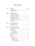
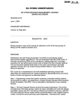
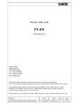
GV-LPR
License Plate Recognition
User Manual
V2.1.3
Table of Contents
Page
Chapter 1
Chapter 2
Hardware Installation
1
1.1 Installation of Video Capture Card
1
1.2 Installation of Key-pro
2
1.3 Installation of the I/O Module
3
1.3.1 Install GV-NET Card
4
1.3.2 Install GV-NET
5
1.3.3 Install GV-I/O
6
1.3.4 Install GV-RELAY
7
Software Installation
9
2.1 Install GV-LPR Application
9
2.2 Install Microsoft Data Access Components (MDAC)
Chapter 3
2.2.1 Check the version of MDAC
12
2.2.2 Install MDAC
14
2.3 Run GV-LPR Application
16
2.4 Uninstall GV-LPR Application
16
System Configuration
17
3.1 Main Screen Features
17
3.2 System Configure
20
3.2.1 System Configuration
Chapter 4
12
20
3.2.1.1 General Setting
20
3.2.1.2 Camera 1 ~ 8
24
3.2.1.3 I/O Device
30
3.2.2 Recognition Setup
35
3.2.3 Integration
38
3.2.4 Export Setup
39
3.2.5 Counter Setting
43
3.2.6 Repeat Recognition Setting
44
3.2.7 Country Setting
44
3.2.8 Video Source
44
3.3 Start/Stop Recognition
45
3.4 Exit/Minimize
45
4.1 Recognition Records
47
4.2 Recognition Database
48
4.2.1 Query
48
i
Chapter 5
Chapter 6
4.2.2 Open Recognition Database
49
4.2.3 Delete Recognition Records
49
4.2.4 Export Recognition Records
49
4.2.5 Image Adjustment
50
4.2.6 View Recognition Video (to be used with DVR integration)
50
4.2.7 View Related Video (to be used with DVR integration)
51
4.3 Watermark Proof
51
Registered Plates Database
53
5.1 Add Record
54
5.2 Edit Record
54
5.3 Delete Record
54
5.4 Find Record
55
5.5 Filter Records
55
5.6 Go to Record
55
5.7 Print
56
5.8 Print Preview
56
Notifications
57
6.1 I/O Notifications
57
6.2 Hotkey View
58
ii
Chapter 1 Hardware Installation
1
CHAPTER
Hardware Installation
The Hardware components included in your system may vary depending on the model or optional features
you purchased. This chapter will describe all available hardware components of the GV-LPR system and its
installation procedures.
1.1 Installation of Video Capture Card
1. Power-off the PC.
2. Insert PCI card into PCI slots.
3. Connect the Hardware Watchdog line.
4. Connect the video camera signal lines.
5. Turn on PC power. Windows will automatically detect the existing cards. Ignore the wizard window and
keep on the following step.
6. Select the driver path in the CD directory \Driver, run DrvInst.exe to install the driver.
Video Extension Port
Real Time Display Card
Connector
Video Input
Audio Input Connector
Watchdog Jumper
GeoVision GV-600v2
GV-600 v2
1
Chapter 1 Hardware Installation
Real Time Display Card
Connector
Audio Input Connector
Video Extension Port
Video Input
Watchdog Jumper
GV-650/GV-750/GV-800
Video Capture Card
Connection of Hardware Watchdog
1.2 Installation of Key-pro
The Key-pro is a 4.7 cm x 2 cm x 0.9 cm blue color USB plug-in key. It can be used for the USB port that
supports USB 1.1 or above. Please plug in the Key-pro in the USB port before lunching the GV-LPR
system. The Key-pro for 1, 2, 4, 6 and 8 lanes are different. Without the Key-pro the system cannot be
run.
2
Chapter 1 Hardware Installation
1.3 Installation of the I/O Module
GV-LPR supports I/O detection mode so that sensors can trigger the GV-LPR to do recognition. This
section describes the installation of the I/O modules.
3
Chapter 1 Hardware Installation
1.3.1
Install GV-NET Card
The GV-NET Card is an interface converter, which converts RS-232 to RS485. It should be installed
inside a PC.
Specifications
RS-232 to PC
RJ-11 to DB9 female cable
RS-485 +
Connect to GV-IO RS-485+
RS-485 -
Connect to GV-IO RS-485 -
Communication
RS-485, 1,200~19,200 bps
DC IN
DC 5V, 1A
Operation
Environmental
temperature
0~50 degree C
Conditions
Humidity
5%~95% (non-condensing)
Compatible Models
GV-NET Card: all models
Dimensions
88mm x 99mm
4
Chapter 1 Hardware Installation
1.3.2
Install GV-COM
GV-COM is a device that converts USB to RS-485 or RS-232. It is to be connected to the USB of
your computer.
Specifications
Serial Interface
Signal: DCD, RxD, TxD, DTR, GND, DSR, RTS, CTS
RS-232
Connecter: DB9 Male
Signal: D+, D
RS-485
Connector: Terminal Block
16 KV ESD for All
Signals
Serial Line Protection
USB 1.1, 1.0
Compliance
USB
USB 2.0 Backward Compatible
Speed
Full speed 12 Mbps
Parity
None, Even, Odd
Data Bit
7, 8
Stop Bit
1 (default), 2
Flow Control
RTS/CTS, XON/XOFF
Speed
600 bps to 115,200 bps
Environmental
Operation
0°C~55°C
Conditions
Temperature
Communication
Parameters
Humidity
Dimensions
5%~95% (Non-Condensing)
103 (W) x 32 (H) x 64 (D) mm
5
Chapter 1 Hardware Installation
1.3.3 Install GV-I/O
The GV-IO is an 8 points digital input and 16 point digital output controller. The dry relay contacts
provide an interface to your external devices such as sensors or detectors. You may use the Normal
Open or Common Connection Point, connect to the GND and IN1~8 of GV-IO respectively. Despite the
connection of the lines, you should also setup in the I/O Setup of the GV-LPR software.
Specification
INPUT
Input
8
Input Signal
0-5 V DC (floating)
High State
5V
Low State
0V
Wiring Label
GND, DI 1~DI 8
Output
16
Output Circuit
TTL Open Collect
OUTPUT
+5V-1, DO 1-1 ~ DO 8-1
Wiring Label
+5V-2, DO1-2 ~ DO 8-2
Communication
RS485, 9600 bps
RS-485+
Connect to GV-NET RS-485+
RS-485-
Connect to GV-NET RS-485-
DC IN
Power Adapter DC 5V, 2A Inner Positive
Environmental
Operation temperature
0~50 degree C
Humidity
5%~95% (non-condensing)
Condition
Dimension
202(W) x 166(H) x 39(D) mm
6
Chapter 1 Hardware Installation
1.3.4 Install GV-RELAY
The GV-RELAY is a relay output module with 8 points relay output interface. This device is to actually
control the gate, light or alarm and connects to the control source of GV-IO output. Despite the
connection of the lines, you should also setup in the I/O Setup of the GV-LPR software.
Specification
Relay Output
RL1~RL8
Relay Control Source
+5V, DO1~DO8 connect Output of GV-IO
Relay Status
Normal Open
Relay Capacitance
P6A / 250V AC; 10A / 125V AC; 5A / 28V DC
Relay ON Time
8ms
Relay Off Time
5ms
Dimension
202(W) x 166(H) x 39(D) mm
7
Chapter 1 Hardware Installation
Please refer to the diagram below for the connection of the GV-NET, GV-IO and GV-RELAY. The
GV-NET can be replaced by the GV-NET Card.
Connection of GV-IO and GV-RELAY
8
Chapter 2 Software Installation
2
CHAPTER
Software Installation
All GV-LPR software applications and the drivers for the GV-Series capture cards are included in the CD
provided within the system package. Please also refer to the images and videos within the CD as a reference
for your installation.
2.1 Install GV-LPR Application
Before starting the installation of GV-LPR, you should check if all the hardware components were
installed properly. It is important that you complete the hardware installation in Chapter one first before
proceeds to the software installation procedures below.
1.
Insert GV-LPR CD into the CD-ROM drive of your PC. Please change to the folder of “Setup” and
run “Setup.exe”.
9
Chapter 2 Software Installation
2.
Click [Browse] if you wish to specify another destination directory otherwise click [Next] to proceed
to the next step.
3.
In the select program dialog box you may change the name for your GV-LPR folder in the empty
text column under Program Folders. If you are not going to do any modification, simply click [Next]
and the installation will start. Follow the rest of the instruction to complete the installation.
10
Chapter 2 Software Installation
4.
Select whether you want to add it to the Startup so that the GV-LPR auto starts running when the
PC is power on. It is suggested to select “yes”.
5.
Finish the setup process. You may select to restart the computer immediately or later. It is
recommended to restart the computer before running GV-LPR application.
11
Chapter 2 Software Installation
2.2 Install Microsoft Data Access Components (MDAC)
Since GV-LPR uses Microsoft Data Access Components (MDAC) version 2.7 or above, please check if
your system has install MDAC before running GV-LPR application. The MDAC checker and installer are
included in “Utility” folder of the install CD.
2.2.1
Check the version of MDAC
1. Please select the folder of “Utility” and then “MdacChecker” from the install CD.
2. Run the “cc.exe”.
3. Please select “Perform analysis of your machine and automatically determine the release
version” and press “OK”.
12
Chapter 2 Software Installation
4. The program will auto detect your MDAC version.
5. If the version is unknown, you may select “View” and then “File Detail” to view the version of
MDAC.
13
Chapter 2 Software Installation
6. If the version is 2.7 or upper, you may skip the next section for install MDAC. Else, you should
follow the instruction of next section to install MDAC.
2.2.2 Install MDAC
1. Please select the folder of “Utility” and then “Mdac2.8” from the install CD.
2. Run “mdac_typ.exe”
3. Please select “I accept all of the terms of the preceding license agreement” and press “Next”.
14
Chapter 2 Software Installation
4. Press “Finish” to start installation.
甲、
5. After complete of installation, please press “Close” to close the dialog and then restart Windows.
15
Chapter 2 Software Installation
2.3 Run GV-LPR Application
1. If you have added GV-LPR to the startup of Windows, it will be run after Windows starts up. Else, run
the GV-LPR application from the GV-LPR folder. You may add a short cut at the desktop if needed.
2. Be sure you have plug in the USB Key-pro mentioned in Chapter 1, or else the system cannot be
run.
3. The first time you run the GV-LPR application, the system will ask you to setup the password of
Administrator. Please setup and DO NOT forget the password.
2.4 Uninstall GV-LPR Application
1. Select the Uninstall icon from the GV-LPR folder to uninstall GV-LPR software.
2. The uninstaller will prompt to confirm before uninstall.
3. The uninstaller will then remove all related files from your hard disk.
4. Images and database created by GV-LPR will not be removed.
16
Chapter 3 System Configuration
3
CHAPTER
System Configuration
GV-LPR application is a Windows based GUI system software that is used for control, setup, and monitor the
GV-LPR System. The detail functions will be explained from Chapter 3 to Chapter 6.
3.1 Main Screen Features
17
Chapter 3 System Configuration
1. Camera Caption
This caption shows the camera name and can be modified. Counter can also be shown here
just after the Camera Caption if it is enabled.
2. Recognition Window PIP
This is a Picture In Picture window, which is by default disabled. When enabled, by default
this window shows the last recognized image. You may change it to show live video instead.
Then the [Main Video Window] will be changed to show the recognized image.
3. Main Video Window
This window default shows live video of the recognition camera. If [Recognition Window PIP] is
enabled, it may be set to show live video or recognized image.
4. Overview Camera PIP
This is a Picture In Picture window. It is default disabled. If an Overview Camera is setup for a
lane, this window can be enabled to show the live video of the Overview Camera. An Overview
Camera can be setup to capture the image of the driver or the overview of the car.
5. Recognition Status
The status of the recognition will be shown here as Registered, Visitors or Unrecognized.
6. Manual Recognition Button
This button is only been shown when [Manual Detect] recognition mode is selected. [Manual
Detect] is normally been used when setting up the system, before the I/O device is ready. You
may press the button to trigger the recognition.
7. Recognition Records
This window shows the recent recognition records up to 5000 records. You may show the
detail and image of the related record by double clicking on the record.
8. Recognition Image
This window shows the last recognized image.
9. Recognition Result
This window shows the date, time, camera name and the result of the last recognition.
18
Chapter 3 System Configuration
10. Registered image
You may set the image of the drivers or the overview image of the vehicles as Registered
Image. The image will be shown when the registered car is being recognized. The function can
be used when the security is very concerned of.
11. Start/Stop Recognition
You may select start or stop one or more lanes of recognition.
12. System Configure
You may setup the system by System Configure. Please refer to the detail in the next section.
13. Notification
I/O and Hotkey Notification. Please refer to Chapter 6.
14. Registered Plates Database
It is used for the management of the Registered Plates Database. Please refer to Chapter 5 for
the detail.
15. Version/ Exit/ Minimize
You may show the version information, select to minimize or exit the GV-LPR application.
16. Recognition Database
It is used for the management of the Recognition Database. Please refer to Chapter 4 for the
detail.
17. View Window layout
You may select to show 1, 4, 6, 8 or 9 windows to monitor the live video of the lanes.
18. Camera Selection
You may select which lane or lanes to be shown in the [Recognition Records].
19. View Window
You may select the live video of a single lane so that you can see it clearly.
19
Chapter 3 System Configuration
3.2 System Configure
When the first time GV-LPR is run, you will be prompted to select the country for your installation. This
setting will define the recognition engine to be used. You may change the setting afterwards.
Please read the detail of System Configure before start using the GV-LPR system. There are 8 setups in
the System Configure. Press the [System Configure] shows the 8 selections.
3.2.1 System Configuration
There are 3 kinds of setting: [General Setting], [Camera 1~8] and [I/O Device]:
3.2.1.1 General Setting
20
Chapter 3 System Configuration
Camera Caption
You may set the Camera Caption, whether turn off the display by selecting [OFF], shows the [Camera ID]
or shows the [Camera ID + Name] at the upper left corner of the Main Video Windows.
File Storage
[Available] displays the available free space of your hard drive. If the first drive hits 2GB then the system
will automatically switch to the second hard drive for recording when there is more than one hard drive
have been assigned for the File Storage.
If [Recycle Files] option is enabled then the system will start deleting the earliest image files to make
space for the new image files when the system runs out of the free storage. If the [Recycle Files] option
is not selected then the system will simply stop saving when there is no free storage.
Click on the [Set Location…] button and the following [Location Setup] dialog will appear. This dialog box
displays the location path of your saved image files and it’s available free space. You can click on the
folder icon to [Add] or [Delete] location path for saving image files.
Note: When integrated with DVR, please Do Not set the folder of video storage path of GV-Series DVR
to the same logical hard drive of GV-LPR File Storage. That will cause the GV-Series DVR to use up the
hard drive.
21
Chapter 3 System Configuration
Image Duplication
If you need to duplicate the image file to other disk for backup or system integration, you may enable
[Image Duplication] and set [Image Duplication Filename Setup] and [Location].
Option
It is advice to set the [Start Recognition At Startup] so that recognition starts when the application starts
running. If [Display Recognition Region] is enabled, the recognized license plate region will be shown. If
[Enable Directdraw Render] is enabled, better video quality can be provided by VGA card and its driver
which supports Directdraw.
Note: Please disable the “Enable Directdraw Render” when you are using dual screen mode when
integrated with GV-Series DVR system because VGA does not support dual screen Directdraw.
Alarm Sound Option
For the Alarm warning, it can be set to be [play once] or [Repeat].
22
Chapter 3 System Configuration
Image Options
The capture image for recognition is 720x480(NTSC) / 720x576(PAL). You may save the image with the
size selected in the [Save Image Size]. [Digital Watermark] can be enabled so that the saved images
could able to be proved that it has not been modified. The [Overlay Time] can write the time in the saved
image file. You may set the font, whether to add [Stereo Frame] and adjust the [Text Alignment].
Password
There are 3 level of privilege for Password: Administrator, Power User and User. Administrator has
highest privilege with all access right. Power User and User cannot do any system configuration. User
cannot add registered license plate into the system but Power User can do it. You may [Add], [Edit] or
[Remove] the password.
23
Chapter 3 System Configuration
3.2.1.2 Camera 1 ~ 8
For 8 lanes product, the dialog will show settings for Camera 1 to Camera 8. For 1 or 2 lanes product, it will
only Camera 1 or Camera 1 and Camera 2 settings etc.
If you press this icon
, the settings inside the rectangle region will be copied to all of the other cameras.
General
[Camera Name] You may set the Camera Name.
[Video Source] You may select the Video Source from Capture Card or AVI file recorded by GV-Series DVR.
You may repeat playing the AVI file if needed. The resolution of video source should be 720x240, 720x480,
720x576, 720x288 or 640x480 depends on the capture card installed from GV-Series.
24
Chapter 3 System Configuration
You may set the [Video Attribute Setup] about for the Brightness, Contrast, Saturation and Hue. When
GV-LPR is integrated with GV-Series DVR system, the [Video Attribute Setup] in GV-LPR will be disabled. You
may set them in the GV-Series DVR system.
Recognition
[Detection Setup]
[Detection Mode] There are [Manual Detection], [I/O Detection] and [Motion Detection] option.
[Manual Detection] is mainly used while setting up the system, testing the recognition
location before setting up the I/O device. You may press the [Manual Recognition button]
(please refer to page 7) in the Main Video Window to trigger the recognition.
[I/O Detection] is normally used for car park or entrance.
[Motion Detection] is normally used on freeway recognition where I/O detection devices are
not allowed to be installed.
[Recognition Result From] There are 1 picture, 3 pictures and 5 pictures options to be selected. It is the
number of images to be captured to be recognized for each trigger. It is used for [Manual
Detection] and [I/O Detection] mode. The greater value provides more accuracy, and more
CPU resource is needed.
[Matching Mode] You may select the tolerance of comparison while performing matching the recognized
result of the license plate with the registered database. There are 4 modes can be selected.
There are All Characters Match, 1 Character Mismatch, 2 Characters Mismatch and 3
Characters Mismatch.
[Setup Recognition Region] You may add or subtract the region where the license plate is to be recognized.
License plates outside this region will not be recognized. To add or subtract the region,
please drag your mouse in the [Recognition Region Setup] area and confirm with the left
button on the mouse.
25
Chapter 3 System Configuration
[Motion Detection]
The settings in the area are only available when [Detection Mode] is selected to be [Motion Detection].
The maximum lanes supported for [Motion Detection] mode is 4 lanes.
[Sensitivity] There are 9 levels of sensitivity can be selected.
[Setup Motion Detection Region] You may add or subtract the motion sensor regions. To add or subtract the
region, please drag your mouse in the [Motion Detection Region Setup] area and confirm
with left button on the mouse.
[Do not record for unrecognized result] This option is default enabled so that those recognition triggered by
motion detection without license plate found can be eliminated.
When [Motion Detection] mode is used, you should be very careful of the installation of the camera. Make
sure that the size of license plate goes in and out of the camera view are nearly the same. Do not install so
that it is a small license plate far away and becomes big when it comes nearer. Please refer to images below
as the guideline.
26
Chapter 3 System Configuration
[Options]
You may set the [Drive Direction] to Incoming or Outgoing.
Notification
[Recognition Window PIP]
You may enable the [Recognition Window PIP] so that the recognized image can be shown in the Picture In
Picture form. By default this window shows the last recognized image. You may change it to show live video
instead by changing the selection. Then the [Main Video Window] will be changed to show the recognized
image.
You may adjust the PIP window by enable the [Display Region] and then setup in the [Recognition Window
PIP Display Region]. You may also reset it to default region by clicking the [Default Region] icon.
[Overview Camera PIP]
You may enable the [Overview Camera PIP] so that you can capture the image of the driver or the overview of
the vehicle by installing another camera and shown in the Picture In Picture window. The image will be saved
accompanied with the recognition image if you enable [Save Image as JPEG File]. You will see 2 images
27
Chapter 3 System Configuration
when you are querying the Recognition Record Database. You may set the image file compression quality in
the [Quality]. Higher quality images require more storage spaces.
You may adjust the PIP window by enable the [Display Region] and then setup in the [Overview Camera PIP
Display Region]. You may also reset it to default region by clicking the [Default Region] icon.
[Notification]
It is used to setup the notify output for the recognition. The selected options will be performed for Registered,
Visitors or Unrecognized result.
[Notify Message]: The input text will be shown on the Monitoring Window.
[Display Time]: Set the time of showing the Notify Message.
[Notify Sound]: Play the selected sound file if it is enabled. It is suggested that this is enabled for the Visitor
and Unrecognizable so that the guards can be warned to take care of the event.
[Save Image as JPEG File]: Option whether to save the image file.
[Quality]: Higher quality images require more storage spaces.
[Edit License Plate]: Option whether to show dialog to modify license plate.
28
Chapter 3 System Configuration
[Video Attribute Setup]
You may set the Brightness, Contrast, Saturation and Hue of the camera.
29
Chapter 3 System Configuration
3.2.1.3 I/O Device
To use [I/O Detect] mode, you should set the [I/O Device]. Please refer to the video demonstration at the
upper left corner of this dialog. It shows to 2 infrared sensors to trigger the recognition. 2 infrared sensors can
prevent most of the trigger generated by people walk through. You can also adjust the distance of the 2
infrared to prevent bicycle or motorbike. Normally, it is at least 1.5 meter apart. Magnetic Loop Detector is the
main sensor device to be used for I/O trigger. For Magnetic Loop Detector, 1 input is enough to trigger the
system.
[I/O Device]
Before you can start using the I/O modules you have to setup the GV-LPR to recognize them first. You should
have a GV-NET Card connected to the COM port of your computer or GV-COM module connected to the USB
port of your computer. Please refer to Chapter 1. Select the device in the [Device] drop down menu, normally
GV-IO, select COM port in [Port] and the module address from [Address], normally 1. Then click [Format
Address] button. The [Add] button will be selectable if the system successfully found your module. Click the
[Add] button and this module will appear in the list. You may remove or edit the device when you select the
device and press [Remove] or [Edit] button.
30
Chapter 3 System Configuration
After adding the I/O device, you may setup the [Pin Setup] of each pin to Normal Open or Normal Close by
clicking the [NO/NC Setup] button.
[Input Setup]
You can select the I/O device to set. Input Setup 1~8 are mainly for triggering recognition. Input Setup 9~12
can be used for auxiliary purpose if needed.
Input Setup 1 is for camera 1 and so on. There are maximum 4 inputs to trigger the recognition of a camera. If
you are only going to set an input to trigger the recognition, you may just enable the input 1. If you are going to
use two inputs to trigger the recognition, you should enable both input 1 and input 2, etc. When you set Input 1
and Input 2 it means that it will trigger recognition only when input 1 is triggered and then input 2 is also
triggered before the trigger of input 1 is off. It will not trigger recognition when input 2 is triggered and then
input 1 is also triggered. This can help when concerning with the drive direction.
31
Chapter 3 System Configuration
[Sensor Name] You may set the name of the sensor in the [Sensor Name].
[Pin Setup] Be remember to set the [Pin Setup] for the Input by pressing the [Pin Setup] button. You should
set the I/O [Module] number and [Pin] number. You may set the [Delay before Trigger] of
recognition if needed.
[Sync Output] If you need to synchronize an output to an input, for example switch on a light when the first
infrared is triggered, you may enable the [Sync Output] and set the [Pin Setup] for it. You may
set the [Delay before Trigger] if needed. The [Trigger Time] can be synchronized with the input
or user defined.
[Sync Application] You may enable it so that a program can be synchronized to run for integration.
[Select Application] You may select the Synchronized Application Path by clicking this button.
[Sync Application Path] The selected Sync Application Path will be shown.
32
Chapter 3 System Configuration
[Output Setup]
There are maximum 8 outputs can be set according to the result of the recognition. Output Setup 1~8 are
mainly for output triggering by recognition result. Other programs can be synchronized to run for integration.
Hot Key can be set to trigger the outputs.
[Output Trigger Name] You may set a meaningful name to identify the trigger, for example “Gate” or “ Light”.
[Pin Setup] Be remember to set the [Pin Setup] for the Output by pressing the [Pin Setup] button. You should
set the Output [Module] number and [Pin] number. You may set the [Delay before Trigger] and
[Trigger Time] if needed.
[Trigger Output Condition]
You should select what kind of recognition result to trigger the output. A
“Registered” result may trigger to open the gate. A “Visitors” or “Unrecognized”
result may trigger an alarm if needed.
[Sync Output] If you need to synchronize an output to an input, like switch on a light when the first infrared is
triggered, you may enable the [Sync Output] and set the [Pin Setup] for it. You may set the
33
Chapter 3 System Configuration
[Delay before Trigger] if needed. The [Trigger Time] can be synchronized with the input or
user defined.
[Sync Application] You may enable it so that a program can be synchronized to run for integration.
[Select Application] You may select the Synchronized Application Path by clicking this button.
[Sync Application Path] The selected Sync Application Path will be shown.
[Hot Key] You may set the Hot Key so that when pressing the Hot Key, the output will be triggered. The Hot
Key can be F1 ~ F8, Ctrl + (A~Z) or Ctrl + (0_9).
34
Chapter 3 System Configuration
3.2.2 Recognition Setup
The system has a default value for the license plate parameters. You may choose not to use this setup
function if your found the default setting is suitable for your environment installation.
The Recognition Setup lets GV-LPR recognition kernel to know the normal size of the license plates. First
select the camera to conduct the recognition setup on, then select a previously captured image by using the
Image Task Bar, or use the [Open] button to choose an image to conduct the recognition setup on. Make
sure to hit [Save] after conducting the recognition setup.
Function Panel
[Open] Use it to open BMP or JPEG files
[Default] Use it to return to default setting
[Save] Use it to save the current setting
[Evaluate] Use it to recognize the license plate inside the image
35
Chapter 3 System Configuration
[Image Task Bar] It lists out captured images using manual detection.
[Camera Task Bar] It lists out the cameras for conducting the recognition setup.
[Plate-to-Image Ratio Info] This information shows the best license plate-to-image ratio for recognition.
[Length & Width of the image & the plate] The length and width of the image file (The length and width of the
license plate)
[Length & Width of the plate] The length and width of the license plate.
36
Chapter 3 System Configuration
5 Easy Steps For The Setup:
Step 1.
First, select the camera to conduct the recognition setup on.
Step 2.
Then select a previously captured image by using the Image Task Bar, or use the [Open] button to choose an
image to conduct the recognition setup on.
Step 3.
Point your mouse arrow sign to the upper left-hand corner of the license plate, left click and hold on to the
click, then drag the arrow to the lower right-hand corner of the license plate, and release the left click.
Step 4.
Hit [Save] to save the current setting.
Step 5.
Hit [Evalute] to see if the characters of the license plate can be recognized. Repeat Step 3 and 4 if
the recognition failed.
37
Chapter 3 System Configuration
3.2.3 Integration
GV-LPR can be integrated with GV-Series Digital Surveillance System (Version 8.0 or higher) by using the
same capture card on a same PC. You may install 2 monitors, with the main monitor showing GV-Series user
interface and the second monitor showing GV-LPR user interface. The main purpose for the integration is that
it could lower the installation cost and provides leading function of retrieving video by license plate number.
Retrieving video by using license plate number provides a very key feature for the integration of GV-LPR with
GV-Series Digital Surveillance System. You may view video of any or all of the cameras before or after the
vehicles being recognized. That means you can easily retrieve the video of suspicious drivers or their
passengers about what they have brought into or out of the building or other behaviors.
Note: Please Do Not set the folder of video storage path of GV-Series DVR to the same logical hard
drive of GV-LPR File Storage. That will cause the GV-Series DVR to use up the hard drive.
Run the GV-Series DVR before GV-LPR. It shares the Video and I/O to GV-LPR.
For the setup of the integration, please follow these steps:
1. Select the [Enable] option.
2. Select correct installed path of the GV-Series for [DVR Path].
3. Match the camera of GV-LPR to DVR by the selection in [Choose LPR Camera] and [Match to DVR
camera]. This function let you to select which camera of GV-Series DVR to share to the GV-LPR for
recognition.
4. If I/O device is used for GV-LPR, please choose whether it is controlled by GV-LPR or controlled by DVR
by selecting [Controlled by LPR] or [Controlled by DVR] in [IO Device]. If DVR does not use the I/O device,
it is better to set it to [Controlled by LPR].
5. Please choose in the [Video Browser] whether to use [Quick Search] or [ViewLog] of GV-Series DVR
when searching function is selected. [Quick Search] provides single channel playback while [ViewLog]
provides all cameras playback with more functions.
38
Chapter 3 System Configuration
3.2.4 Export Setup
Export Setup enable you to output the recognition result for system integration. There are 2 ways to export the
result. You may select [Export by RS232] or [Export to File].
[Export by RS232]
You should first select the [Export through RS232] export selection. Then, enable the [Enable] in [RS232
Setup] and select the COM port and set the communication properties of the COM port by pressing the [COM
Properties] button. [Save Returned Ticket Number] can be used when integration with Ticketing System. The
Ticketing System should send the received data and add the Ticket Number, [Card ID] in the last field and
send back to GV-LPR. The [Card ID] will be received and can be used to search for the recognition record.
39
Chapter 3 System Configuration
You may select all recognition result to export or just some of the condition, for example just Registered and
Visitors. Unrecognizable license plates are outputted as ******.
You may enable the Prefix, Separation between Data, and Suffix if needed.
Please notice the content of the Data Select. You may output not only the license plate number [License Plate]
but also [Camera], [Recognition time], [Stay time], [Drive Direction], [Host Name], [Recognition Confidence]
and [Identify]. [Identify] equal to 0 means that is a [Registered], equal to 1 means [Visitors], and 2 means
[Unrecognized]. They could be separated by [Separation Content] mentioned above. You have to enable the
[Enable] option and set the [Length (Bytes)] for the Data you are going to export.
40
Chapter 3 System Configuration
[Export to File]
You should first select the [Export to File] export selection. Then, enable the [Enable] in [File Setup], set the
[Path] by using the [Select Location] button or manually input the path. Set the [Filename Extension] and
whether the file is to be appended in the [Data Append].
You may select all recognition result to export or just some of the condition, for example just Registered and
Visitors. Unrecognizable license plates are outputted as ******.
You may enable the Prefix, Separation between Data, and Suffix if needed. They take effect in the filename
and data of the exported file.
Please notice the content of the Data Select. You may output not only the license plate number [License Plate]
but also [Camera], [Recognition time], [Stay time], [Drive Direction], [Host Name], [Recognition Confidence],
[Identify],[Recognition Image Fullpath] and [Relation Image Fullpath]. [Identify] equal to 0 means that is a
[Registered], equal to 1 means [Visitors], and 2 means [Unrecognized]. They could be separated by
[Separation Content] mentioned above.
41
Chapter 3 System Configuration
If you want the Data to be in the filename, set the [Enable] to [Yes]. If you want the Data to be written to the
exported file, set [Write to file] to [Yes]
Example: If you are going export [License Plate] data and the filename is [Camera], then you may select as:
and
Then you may have a file named “EVENT_1.txt” generated with content of “AB1234” when a vehicle with
license plate number “AB1234” is recognized by the camera 1. If the [Data Append] is not enabled, the
content of the file will be just a new line of data of the last recognition. If it is enabled, a new line of data will be
appended to the last line of the file for each recognition.
For the [Select Data] of [Recognition Time], you may set the option of each unit in detail.
42
Chapter 3 System Configuration
3.2.5 Counter Setting
You may use the counter to count the traffic flow or count the remaining empty unit of parking lots. The result
can be shown on the Camera Caption and optionally output to file.
1. First, enable the [Enable] option. Then select the camera from [Incoming] and/or [Outgoing]. The [Drive
Direction] of each camera decides whether it is placed in [Incoming] or [Outgoing]. [Incoming] increases
the counter and [Outgoing] decreases the counter. More than one camera can be set for a group of count.
2. Select the [Identity] to count.
3. Set the [Initial Counter].
4. Select whether to enable [Increase counter when hotkey is pressed].
5. Select whether to enable [Export counter to file].
6. Press the [Add] button to add a new counter. Press [Edit] after you have modify the settings of a counter.
You may manually input the path of [Export location Setup] or by pressing the [Set Location] button.
If you are going to count the remaining unit of parking lot, you may set the [Initial Counter] to current empty
unit and reverse the option of [Incoming] and [Outgoing] option of the camera so that increase or decrease
function is correct.
43
Chapter 3 System Configuration
3.2.6 Repeat Recognition Setting
Repeat Recognition can only be enabled when the [I/O Detection] mode is applied. The system will repeat
recognition until the vehicle leaves the I/O sensor or the recognition result is “Registered” or at least “Visitors”.
This function will increase the recognition rate. For the system used for a car park for registered car, it is
suggested to set to “Registered”. For the non-registered usage like public car park, it is proposed to set to
“Registered” plus “Visitors”.
3.2.7 Country Setting
You have to select the country or region where you are installing the GV-LPR. The recognition engine for
different country is different. Please make sure you have selected the correct country or region.
3.2.8 Video Source
You may select the video standard to be NTSC or PAL here.
44
Chapter 3 System Configuration
3.3 Start/Stop Recognition
Press
[Start/Stop Recognition] icon to start or stop recognition. You may select start or stop one or
more cameras of recognition.
3.4 Version/Exit/Minimize
Use the
[Version/Exit/Minimize] icon to show the version, select to exit or minimize the program.
45
Chapter 3 System Configuration
46
Chapter 4 Recognition Database
4
CHAPTER
Recognition Database
You can use [Recognition Records] or [Recognition Database] to view the recognition records. The database
records the image, camera, recognized license plate number, time, direction etc. A hard drive of 80G can
record about 1 millions records of data.
4.1 Recognition Records
You may view the latest recognition records from the [Recognition Records]. The number button at the right
hand side is the switch for you to select the records from which cameras are to be shown.
Double click any of the records will show the [Event View]. You can get more information from the [Event
View], for example the image of the vehicle or image of the driver. You may press the [Set Image as
Registered Image] so that when next time the vehicle is recognized, the registered vehicle image is shown.
47
Chapter 4 Recognition Database
4.2 Recognition Database
You may press
[Recognition Database] icon to view the recognition records. [Recognition Database]
provides functions of Query, Open Database, Delete Record, Print and Print Preview. Records being queried
will be shown with detail items and license plate image plus relation image if Overview Camera has been
setup.
4.2.1 Query
You may query the records by selecting the [Camera], [License Plate] and the recognize result status. License
plate number can be search in [All Characters Match] mode or partially match. [All Characters Match] mode is
faster. There are also options of [Arrival_time] or [Departure_time] to be selected. [Start Time] and [End Time]
are also adjustable. [Card ID] can also be search for if it is integrated with ticketing system.
48
Chapter 4 Recognition Database
4.2.2 Open Recognition Database
You may open a previously exported Recognition Database to Query, Delete Record or Print.
4.2.3 Delete Recognition Records
Select the records to be deleted and press the Delete button.
4.2.4 Export Recognition Records
1. Select the records to be exported.
2. Select to export to [Microsoft Access] format or [HTML document] format.
3. Select the path and input the filename to export.
49
Chapter 4 Recognition Database
4.2.5 Image Adjustment
The Image can be adjusted for Brightness, Contrast, Stretch, Equalize and Normalize.
4.2.6 View Recognition Video (to be used with DVR integration)
You may press
button to launch [Quick Search] or [ViewLog] of GV-Series DVR to watch the video
recorded when the vehicles enter the recognition region. Features of [Quick Search] are listed below. For
features of [ViewLog], please refer to the user manual of GV-Series DVR.
No.
Name
Description
1
2
Monitoring Window
Mode Switch
3
4
5
ViewLog
Time Period
Playback Panel
6
Exit
Displays video associated to the event
Click these buttons to enable or disable Transaction Window and to
switch between 640x480 or 320x240 display.
Click to open ViewLog application.
Use these buttons to search event within the specified time.
Includes Play, Pause, Previous 10 frames, Home, Next 10 frames, End
buttons.
Click to close Quick Search screen
50
Chapter 4 Recognition Database
4.2.7 View Related Video (to be used with DVR integration)
You may press
button to launch [Quick Search] or [ViewLog] of GV-Series DVR to watch the video
recorded by the Overview Camera when the vehicles enter the recognition region.
4.3 Watermark Proof
GV-LPR system offers a highly secure solution to protect digital images and video against unauthorized
alteration or manipulation. To add watermark to recorded images, please refer to Chapter 3.
This allows all
recorded images be marked with permanent and inseparable image. Since the watermark is invisible to the
naked eye, in order to see it the video stream must be open in a watermarking verification program. The
Water Mark Proof program is able to verify video and image. In GV-LPR, we only use its image verification
function.
1. To run the verification process, please press [Recognition Database]
2. Select the file to be verified.
3. The verification result will be show as below:
51
and select “Watermark Proof”
Chapter 4 Recognition Database
Following table explains functions of each icon:
Name
Description
Open File
Click and select a video or image file to verify.
First Frame
Go the first frame of the file. (Only for Video file)
Play
Play the file. (Only for Video file)
Previous Frame
Go to the previous frame of the file. (Only for Video file)
Next Frame
Go to the next frame of the file. (Only for Video file)
Previous Watermarked Frame
Next Watermarked Frame
Go to the previous frame that contains watermark. (Only
for Video file)
Go to the next frame that contains watermark. (Only for
Video file)
The Watermark Proof displays the verifying result as follows:
Similar rate: If the image has not been tampered with, the Check sum displays a rate over 90%.
Otherwise a rate lower then 90% will be treated as tampered.
Original vs. Extracted:
The Extracted section should have the same icon displayed as the one in the
Original section. If not it indicates the image may have been altered.
52
Chapter 5 Registered Plates Database
5
CHAPTER
Registered Plates Database
Registered Plates Database is designed for the matching of the recognition result. Match to open the gate or
match to warn the police is a common application.
By clicking
[Registered Plates Database] icon, you may add new, edit, query, delete or print the
records of the registered vehicles. The records include ID, License Plate, Name, Identity, Ticket, Telephone
number, Address, Memo, the image of the vehicle owner or the overview of the vehicle. The image will be
shown when the vehicle is recognized.
53
Chapter 5 Registered Plates Database
5.1 Add Record
You may add a new record by pressing the
icon. Then input each item of the record. You must input
[License_Plate] item in the record, others are optional. You may also add the image of the owner or the
overview of the vehicle for the guards to do double check. If [Activation Date] is set, it will be activated on the
date. If it is not set, it will be activated when this record is added. If [Expiration Date] is set, it will be expired on
the date. If it is not set, it will not be expired. The [valid camera] is used to set the valid camera for this license
plate number. If for example, the vehicle is not permitted for entrance of camera 3, then for 8 lanes solution,
this value should be set as “1245678”. When this vehicle is recognized by camera 3, it is identified as “Visitor”.
The default value for it is valid for all cameras.
5.2 Edit Record
You may edit a record by selecting a record and then press the
[Edit] icon.
5.3 Delete Record
You may delete a record by selecting a record and then press the
54
[Delete] icon.
Chapter 5 Registered Plates Database
5.4 Find Record
You may find a record by pressing the
[Find] icon. Select the [Field], input the text you are looking for in
[Find What] and set the [Match] option and search [Direction]. Then press the [Find Next] button to find.
5.5 Filter Records
It is also a good way to use filter to filter out the records you are looking for. First, press the
[Filter] icon.
Then, you can set many options for each record [Field] and then use [AND] or [OR] operation. If you are going
to turn off the filter, just press the filter icon again.
5.6 Go to Record
You may go to the first record by pressing
icon.
You may go to the previous record by pressing
icon.
You may go to the next record by pressing
icon.
You may go to the last record by pressing
icon.
55
Chapter 5 Registered Plates Database
5.7 Print
You may print the records by pressing
icon.
5.8 Print Preview
You may preview before printing the records by pressing
56
icon.
Chapter 6 Notifications
6
CHAPTER
Notifications
Notification provides I/O status and the Hotkey View so that you can get the status from the system. It helps
you when you are going to check the I/O devices.
6.1 I/O Notifications
Press the
[Notification] icon and select
[I/O Notification]. Then you can get the
current status of the I/O module. From the left of the dialog, you can get the Name, Port, Address of the I/O
module and NO or NC setting of each pins. From the right of the dialog, you can get the current trigger status
of the I/O pins. The example below shows that I/O input pin 1 (DI 1) is triggered.
57
Chapter 6 Notifications
6.2 Hotkey View
Press the
[Notification] icon and select
[Hotkey View]. The left part of the dialog
shows the Hotkey you have set in [Output Setup] of [I/O Device] in [System Configuration]. The right part of
the dialog shows the description of the selected Hotkey.
58