1
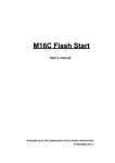
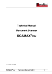
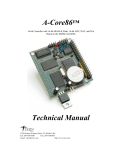
APPLICATION NOTE
M16C
Firmware Requirements for In-Circuit Debugger
1.0 Abstract
The USB-Monitor is a low cost, compact interface that has two functions for Renesas’ M16C Flash
microcontrollers: 1) an in-circuit debugger tool with KD30 Debugger, and 2) an in-system programmer with
FoUSB (Flash-over-USBTM) Flash Programmer. The following article introduces the target MCU resources used
when the USB-Monitor is used for in-circuit debugging.
2.0 Introduction
When used with KD30, the USB-Monitor provides an easy-to-use in-circuit debugging environment during
application development. In addition, when used with the FoUSB Flash Programmer, it also provides an
in-system programming interface to the target Renesas M16C Flash MCU.
The USB-Monitor, by taking advantage of Universal Serial Bus (USB), provides plug-and-play connectivity and
fast data transfers between the computer and the M16C target board. The USB-Monitor is powered by Renesas’
M37641 full speed USB Flash MCU, which also makes it upgradeable to support future Renesas M16C MCUs.
Powering the USB-Monitor is user selectable: USB Bus powered or Target powered. When used in bus-powered
mode, the USB bus supplies power to the USB-Monitor and target board. When in target-powered mode, USB
bus power is disconnected and the USB-Monitor sources power from the M16C target board. Renesas
recommends to use Target Power Mode and NOT USB Bus Power Mode when connected to non-Renesas SKP
target boards. If you plan to use the USB-Monitor to supply power to non-SKP boards, please contact Renesas
representative for details and assistance.
Aside from a standalone kit (RTA-FoUSB-MON), the USB-Monitor comes included with the following Renesas
Starter Kits:
• MSV30102-SKP
• MSV30262-SKP
• MSV30245-SKP
• M16C System Evaluation Kit
REU05B0028-0100Z
June 2003
Page 1 of 7
M16C
Firmware Requirements for In-Circuit Debugger
PC with Windows™ 98, 2000, Me,
or XP and available USB port
Figure 1 USB-Monitor System Connectivity
3.0 Target MCU Resources Used by USB-Monitor for In-Circuit Debugging
This section describes the M16C MCU resources used by the USB-Monitor for in-circuit debugging (with the
KD30 Debugger). These resources are NOT used when the USB-Monitor is used for programming (with the
FoUSB Programmer). See references for details on how to connect the hardware for in-circuit debugging or
in-system programming support.
When used as debug interface, the USB-Monitor downloads a small program, called a ROM Monitor or MCU
Monitor Image (MMI), to the target M16C MCU to establish communications used for program debugging
operations. This ROM Monitor is downloaded to the target when KD30 application is started.
It is important to note that the operation of the USB-Monitor is transparent to the user. There is no special
software processing required to be able to use it as long as the user understands the exceptions and follows the
rules described below.
Note: These resources are ONLY used when the USB-Monitor is used for in-circuit debugging. Only the MCU pin
resources are used when the USB-Monitor is used for in-system programming.
3.1 ROM
The ROM monitor code is located in the M16C memory space starts at address 0FF900H to 0FFE80H. KD30 will
display a message on any attempt to overwrite specified ROM location.
Rules on ROM usage are described below.
• User memory allocated to the ROM monitor should not be used. Any attempt to use this area by the user code
will be ignored.
• The special page vector table is mapped from 0FFE00H to 0FFFDBH. It is suggested that, if special page
jumps are used, the special page numbers start with the minimum value of 20 and increases to a maximum of
127 to accommodate future monitor size increases.
3.2 RAM
The ROM monitor utilizes 128 bytes of RAM memory located at the top of MCU RAM area. For example, on an
REU05B0028-0100Z
June 2003
Page 2 of 7
M16C
Firmware Requirements for In-Circuit Debugger
M30624 MCU, there is 20Kbytes of RAM located from 00400H to 053FFH. In this case, the monitor will be using
the addresses from 05380H to 053FFH. In addition, the monitor also uses 4 bytes (max) of RAM on the interrupt
stack.
3.3 Interrupts
For all MCU’s that do NOT support DBC interrupt, the ROM monitor requires that the receive interrupt vector for
the monitor/boot UART MUST point to the communications entry point of the monitor, which is 0FF900H. In
addition, the monitor reserves the following hardware interrupt vectors for its own use:
• BREAK vector (0FFFE4H)
• ADDRESS MATCH vector (0FFFE8H)
• SINGLE STEP vector (0FFFECH)
• DBC vector (0FFFF4H)
The user code download process will properly load values into these locations. User code that globally disables
interrupts for long periods of time (>1 second), may interfere with the proper operation of the monitor.
Note: For MCU’s that do NOT have DBC interrupts, always ensure that the global interrupt is enabled in the startup
files. Communications between USB-Monitor and M16C MCU ROM Monitor will fail when the global interrupt is not set
or disabled for long periods (>1s). This is the primary cause of communication errors while using the KD30 Debugger.
Table 1 M16C MCU Support Summary
M16C MCU
Boot UART/SIO
DBC Irq Support
Breakpoints
M30100F3
UART0
No
2
M30245FC
UART1
No
2
M30262F8
UART1
Yes
6
M3062GF8N
UART1
No
2
M30620FCA
UART1
No
2
M30624FGA
UART1
No
2
M30626FGP
UART1
Yes
8
M306V7FG
UART0
No
2
3.4 Peripherals
The ROM monitor uses the serial port associated with the boot mode of the MCU for communication with the
USB-Monitor. Connect the SCLK, TxD, RxD signals from the 10-pin header to this serial port. For example, in the
case of M30624 MCU, the monitor uses UART1 as the boot UART.
For MCU’s that do NOT support DBC, ensure that the interrupt vector for this serial port/UART is set to FF900h.
Avoid byte-writes to the (boot UART/SIO) port, including direction register, associated with the SIO when the
other half of the port is used as General Purpose I/O (GPIO) pins. Byte-writes to the port and direction register
REU05B0028-0100Z
June 2003
Page 3 of 7
M16C
Firmware Requirements for In-Circuit Debugger
may prevent the monitor program from functioning properly. Use read-modify-write instructions instead.
If possible, avoid using this serial port for other applications in the firmware when USB-Monitor will be used for
development.
3.5 Real-Time Capability
Please be aware that while the ROM monitor is in its “STOP”ed state, the hardware peripherals will continue to
run. Therefore, interrupts may not be serviced properly. Also, the watchdog timer will not be serviced and will
likely timeout if active.
Note: While the ROM monitor is in its “RUN”ning state, there is no overhead on the application code, UNLESS a RAM
monitor window is open in KD30. This window requires periodic communication with the MCU. This communication
suspends normal application operation while servicing the request (approximately 2000 BCLK cycles for each 16 bytes
of data displayed in the window are used per window update). The user must determine whether or not, this behavior
is acceptable.
3.6 Software Summary and Precautions
• Ensure that global interrupt is set in the startup file and not disabled for long periods (>1s).
• Do NOT use the RAM or ROM memory as specified in sections 3.1 ROM and 3.2 RAM.
• Avoid byte-writes to the port and direction register to avoid interfering with monitor operation associated with
the boot SIO/UART. Use bit manipulations.
• Do NOT change boot UART configuration.
• Ensure that the boot SIO/UART vector is properly setup to point to FF900H for those M16C MCU’s that don’t
have DBC interrupt.
• Do NOT attempt to debug watchdog, WAIT mode, or STOP mode.
• Do NOT execute a ‘STEP’ operation after a write to PRC2 SFR.
4.0 Conclusion
The USB-Monitor is an easy-to-use interface for setting up an M16C MCU development environment to support
in-circuit debugging. It does not require a lot of resources from the target board. Correct hardware connectivity
will guarantee proper operation.
REU05B0028-0100Z
June 2003
Page 4 of 7
M16C
Firmware Requirements for In-Circuit Debugger
5.0 Reference
Most of the information used to make this application note can be found on the USB-Monitor’s Users Manual. For
detailed information about the USB-Monitor such as application software, driver installation, troubleshooting, etc.,
please refer to the Users Manual.
If unsure or to verify your hardware setup, contact your Renesas representative for assistance.
Renesas Technology Corporation Semiconductor Home Page
http://www.renesas.com
E-mail Support
[email protected]
User’s Manual
• RTA-FoUSB-MON User’s Manual
• Target Setup for FoUSB Programmer App Note
• Target Setup for In-Circuit Debugger App Note
REU05B0028-0100Z
June 2003
Page 5 of 7
M16C
Firmware Requirements for In-Circuit Debugger
6.0 Software Code–Startup File Examples for USB-Monitor Support for Debugging
Operations (MCU with NO DBC support)
Following is a simple program written for Renesas’ NC30 compiler to illustrate how to set up Pulse Output Mode
on timer A0. 6. Software Code – Startup File Examples for USB-Monitor Support for Debugging Operations
(MCU with NO DBC support)
A startup file (ncrt0.a30) example for the M16C/10 (M30102) MCU with global interrupt enabled, and highlighted,
is shown below. For M16C MCU’s with DBC interrupt, the global interrupt need not be enabled unless the
application requires the use of maskable interrupts.
;*************************************************************************** ;
;
C COMPILER for M16C/10 with USB-Monitor support.
;
Copyright 2003 Renesas Technology America, Inc.
;
All Rights Reserved.
;
;
ncrt0.a30 : NC30 startup program for M16C/10 devices.
;
;
This program is applicable when using the basic I/O library
;
;
$Id: ncrt0.a30, v 1.12 2000/05/18 06:44:37 simomura Exp $
;
;
This startup program is setup for use with the USB-Monitor.
;
Source code ROM area is from 0xFA000 to 0xFF800 (22.5K bytes).
;
Available ram memory is from 0x400 0x770 (880 bytes).
;
Heap memory area is zeroed out. If using standard libraries
;
heap memory area will have to be specified.
;
UART0 is used by the USB-MONITOR, and is not available for application.
;
Modified for use in Mini 10 Board development.
;***************************************************************************
:
:
ldc
#data_SE_top, sb
; set sb (stack base) register
ldintb #VECTOR_ADR
fset
i
;enabling interrupts. Do NOT disable
;interrupt when using USB-Monitor
;====================================================================
; NEAR area initialize.
;-------------------------------------------------------------------;
N_BCOPY
data_NOI_top,data_NO_top,data_NO
:
:
REU05B0028-0100Z
June 2003
Page 6 of 7
M16C
Firmware Requirements for In-Circuit Debugger
An example of a sect30.inc file for the M16C/10, where the SIO/UART receive interrupt vector points to the ROM
monitor (FF900h), is shown highlighted below. For M16C MCU’s with DBC interrupt, the vector declaration is not
required.
;*******************************************************************************
;
;
C Compiler for M16C/10
;
Copyright 2003 Renesas Technology America, Inc.
;
All Rights Reserved.
;
;
Written by T.Aoyama
;
;
sect30.inc
: section definition
;
This program is applicable when using the basic I/O library
;
;
$Id: sect30.inc,
v 1.9 2000/06/20 09:07:11 simomura Exp $
;
;******************************************************************************
:
:
.lword dummy_int
; Software INT #15
.lword dummy_int
; Software INT #16
.lword dummy_int
; uart0 transmit(for user)(vector 17)
.lword 0FF900h
; uart0 receive(for user)(vector 18) For USB
; Monitor - DO NOT CHANGE!!
.lword dummy_int
; uart1 transmit(for user)(vector 19)
.lword
dummy_int
; uart1 receive (vector 20)
.lword dummy_int
; Timer1 Interrupt (vector 21)
.lword dummy_int
; TimerX Interrupt (vector 22)
:
:
REU05B0028-0100Z
June 2003
Page 7 of 7
Keep safety first in your circuit designs!
• Renesas Technology Corporation puts the maximum effort into making semiconductor products
better and more reliable, but there is always the possibility that trouble may occur with them. Trouble
with semiconductors may lead to personal injury, fire or property damage.
Remember to give due consideration to safety when making your circuit designs, with appropriate
measures such as (i) placement of substitutive, auxiliary circuits, (ii) use of nonflammable material or
(iii) prevention against any malfunction or mishap.
Notes regarding these materials
• These materials are intended as a reference to assist our customers in the selection of the Renesas
•
•
•
•
•
•
•
Technology Corporation product best suited to the customer's application; they do not convey any
license under any intellectual property rights, or any other rights, belonging to Renesas Technology
Corporation or a third party.
Renesas Technology Corporation assumes no responsibility for any damage, or infringement of any
third-party's rights, originating in the use of any product data, diagrams, charts, programs, algorithms,
or circuit application examples contained in these materials.
All information contained in these materials, including product data, diagrams, charts, programs and
algorithms represents information on products at the time of publication of these materials, and are
subject to change by Renesas Technology Corporation without notice due to product improvements
or other reasons. It is therefore recommended that customers contact Renesas Technology
Corporation or an authorized Renesas Technology Corporation product distributor for the latest
product information before purchasing a product listed herein.
The information described here may contain technical inaccuracies or typographical errors.
Renesas Technology Corporation assumes no responsibility for any damage, liability, or other loss
rising from these inaccuracies or errors.
Please also pay attention to information published by Renesas Technology Corporation by various
means, including the Renesas Technology Corporation Semiconductor home page
(http://www.renesas.com).
When using any or all of the information contained in these materials, including product data,
diagrams, charts, programs, and algorithms, please be sure to evaluate all information as a total
system before making a final decision on the applicability of the information and products. Renesas
Technology Corporation assumes no responsibility for any damage, liability or other loss resulting
from the information contained herein.
Renesas Technology Corporation semiconductors are not designed or manufactured for use in a
device or system that is used under circumstances in which human life is potentially at stake. Please
contact Renesas Technology Corporation or an authorized Renesas Technology Corporation product
distributor when considering the use of a product contained herein for any specific purposes, such as
apparatus or systems for transportation, vehicular, medical, aerospace, nuclear, or undersea
repeater use.
The prior written approval of Renesas Technology Corporation is necessary to reprint or reproduce in
whole or in part these materials.
If these products or technologies are subject to the Japanese export control restrictions, they must be
exported under a license from the Japanese government and cannot be imported into a country other
than the approved destination.
Any diversion or reexport contrary to the export control laws and regulations of Japan and/or the
country of destination is prohibited.
Please contact Renesas Technology Corporation for further details on these materials or the
products contained therein.