1
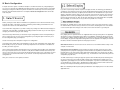
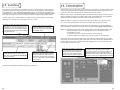
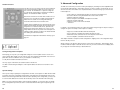
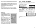
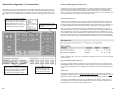
Contents
Important Safety Instructions ................................................................. i
I. Overview ...................................................................................................1
II. Sample Systems ................................................................................. 2
III. Getting Started ................................................................................... 5
IV. Basic Configuration .......................................................................... 8
V. Advanced Configuration ................................................................... 17
VI. Scheduling Events and Security ..................................................... 27
VII. Email Alerts and Monitoring .......................................................... 29
VIII. Wiring the NRC ............................................................................... 30
IX. Connecting the Devices on the SP Bus .......................................... 31
Troubleshooting .................................................................................... 33
Copyright ......................................................................................... 33
PX2-NRC-1142 User’s Manual November 2009
I. Overview
Important Safety Instructions
1) Read these instructions.
2) Keep these instructions.
3) Heed all warnings.
4) Follow all instructions.
5) Do not use this apparatus near water.
6) Clean only with dry cloth.
7) Do not block any ventilation openings. Install in accordance with the manufacturer's instructions.
8) Do not install near any heat sources such as radiators, heat registers, stoves, or other apparatus
(including amplifiers) that produce heat.
9) Do not defeat the safety purpose of the polarized or grounding type plug. A polarized plug has two
blades with one wider than the other. A grounding type plug has two blades and a third grounding
prong. The wide blade or the third prong is provided for your safety. When the provided plug does not
fit into your outlet, consult an electrician for replacement of the obsolete outlet.
10) Protect the power cord from being walked on or pinched particularly at plugs, convenience receptacles, and the point where they exit from the apparatus.
11) Only use attachments/accessories specified by the manufacturer.
12) Use only with a cart, stand, tripod, bracket, or table specified by the manufacturer, or sold with the
apparatus. When a cart is used, use caution when moving the cart/apparatus combination to avoid injury from tip-over.
13) Unplug this apparatus during lightning storms or when unused for long periods of time.
14) Refer all servicing to qualified service personnel. Servicing is required when the apparatus has
been damaged in any way, such as power-supply cord or plug is damaged, liquid has been spilled or
objects have fallen into the apparatus, the apparatus has been exposed to rain or moisture, does not
operate normally, or has been dropped.
WARNING - To Reduce the Risk of Fire Or Electric Shock, Do Not Expose This Apparatus To Rain Or
Moisture.
What is the NRC and what does it do?
The PixieProTM Networked Room ControllerTM (PX2-NRC-1142) is generally designed to be the central
control device for audiovisual systems. The NRC can be configured, controlled, and monitored via a
friendly Web interface, and controlled from a wall-mounted button panel (sold separately). You can
control virtually any display device, switcher, or peripheral device using the NRC's single RS-232 control port, one IR control port, and four low-voltage relays. It also has two general purpose input sense
ports that can detect low-voltage relay closure and initiate actions triggered by external events.
How does it control an audiovisual system?
The NRC can function as a stand-alone control device by connecting it to a network and accessing it
with a Web browser on a computer that is connected to the same network. (In fact, using the Webbased interface is how the NRC must be configured.) Most people will want in-room control in addition to Web-based control. In those cases, the NRC can be connected to a PixiePro Modular PanelTM
(PX2-MP-IR) as its front-end "button-pressing" control interface. The NRC will still be the brains in the
installation and will initiate all control actions, while the Modular Panel will simply provide the in-room
button interface.
The NRC is designed to directly control only the display device (i.e., projector or monitor) with its RS232 port and IR port. It can also directly control electric screens and lifts with its low-voltage relays. If
you have other devices to control in the room (e.g., DVD player, switcher, amplifier), you will need to
extend the NRC's capabilities using Control PucksTM. For example, we offer a Puck with four IR ports
(PX2-PUC-IR-4), a Puck with an IR port and an RS-232 port (PX2-PUC-23/-IR), and a Puck with four
relay ports (PX2-PUC-REL-4). Wiring the Pucks and the Modular Panel to the NRC is simple: daisychain them using CAT5 cable with RJ-45 connectors.
How to get the most out of this manual
Apparatus shall not be exposed to dripping or splashing and no objects filled with liquids, such as
vases, shall be placed on the apparatus.
Most readers probably want to get started configuring your NRC and don’t want to bother reading
through the whole manual. If you’ve never configured one before, you’ll definitely need at least part of
this as a guide. Here’s a quick rundown of what each chapter is about:
Electrical Warning
Chapter II — Gives a range of examples of what the NRC can do. (First-timers only)
Chapter III — Details how to get a new NRC online and ready to configure. (Necessary for firsttimers, and good to use as a quick reference guide)
Chapter IV — EVERY USER should read this chapter! This walks you through the basics of configuring the NRC. It emphasizes how to configure the NRC to control a single display device. This chapter
is absolutely necessary for all users.
Chapter V — Builds on Chapter IV, and describes how to configure the NRC to control rooms with
multiple different devices, and some of the advanced technical features of the NRC. This chapter
should be read by anyone who wants to use the NRC to control a more complex system than just a
display.
Chapter VI — Scheduling events and security: if you need ‘em, read it. If you don’t, skip this chapter.
Chapter VII — Email alerts and monitoring
Chapter VIII — RS-232 and IR wiring for the NRC
Chapter IX — Connecting SP Bus devices
Troubleshooting — Solutions to common problems
The PX2-NRC-1142 is a low-voltage device. Never install the Networked Room Controller in an electrical back box containing high-voltage wiring. This would cause a serious electrical danger and violate United States national electrical codes.
i
1
II. Sample Systems
System 2:
A few real-world examples of systems that the NRC can control will give you a clearer view of the
NRC’s capabilities. What follows are three examples of systems that could be controlled using the
NRC, Modular Panel, and Control Pucks in various configurations. (Note: these examples are not the
only possible set-ups; they're simply a few common types to help illustrate some of the things you can
do with the NRC family.)
System 1:
NRC and Modular Panel combined as control system for a projector, with
the relays on the NRC being used to control a lift and a screen.
Relay Control
Automated Lift
NRC as stand-alone control device for a projector. NRC controls the
projector with RS-232 and IR.
Network
nI oe
di V
Network
RS-232 and IR
Video Signal
SP Bus
PX2-MP-IR
The NRC can act as a stand-alone control device for rooms where you don't need a wall-mounted
controller. In this case the simplest possible set-up for the NRC — you'd have the NRC installed at
the projector and powered there. It will control the projector with RS-232 and IR (in this example, both
are used to control the projector, but some projectors will simply use one or the other). The NRC must
be connected to a local network or the Internet. To access its functions, use a Web browser that has
access to the same network that the NRC is on, and log in to the NRC to monitor, configure, and control it.
2
As with Example 1, the NRC controls the projector with RS-232 and IR, it is on the network and it can
be controlled via the Web interface. Additionally, the Modular Panel in this example can be used for
in-room control. Also, the NRC’s low-voltage relays are used to raise and lower a screen and a lift.
3
III. Getting Started
System 3:
Configuring the NRC to Operate Without Network Control
NRC and Modular Panel combined to control a projector, with the relays on the NRC used for a
screen. It “listens” for contact closure on one of its sense ports, which triggers a theft warning email. An IR Puck controls a DVD player and a VCR. One RS-232/IR Puck controls an amplifier-receiver.
Sense Port
Control Relay
(wired to security loop)
(screen control)
Some users will wish to take advantage of the NRC control capabilities without using its network interface. If this is what you wish to do, follow the first four steps of the configuration process described in
this section in order to connect your PC to the NRC for configuration. Then Proceed to Chapter IV.
Basic Configuration and configure the unit directly from your PC.
Important: If you do not plan to put your NRC online, you will need to download the NRC and Puck
drivers you need from our website before configuring the NRC:
http://www.spcontrols.com/downloads_index.php
Video
The first time you connect for configuration, the NRC will automatically create the appropriate driver
directories on your hard drive. You can also add the new directory locations yourself :
NRC projector/monitor drivers: C:\~\My Documents\SP Controls\smartpanel\drivers
Puck RS-232 or IR drivers: C:\~\My Documents\SP Controls\nrc\drivers
10 steps to get the NRC online
Step 1: Get answers to these questions from your network administrator
Network
Will the NRC use a static IP address or DHCP?
If the NRC will be using a static IP address, what will the IP address, subnet mask, gateway, primary DNS, and secondary DNS will be assigned to this NRC?
SP Bus
IR Puck (controls
combo unit)
•
•
RS-232 Puck
(controls amp)
• If the NRC will be using DHCP, what IP address will be assigned by the DHCP server? You’ll need
to provide your network administrator with the MAC address from this NRC so he or she can assign a
unique IP address to it. The MAC address can be found under the ‘Network’ tab in the Configuration
section. (See Figure 3)
MAC address
Step 2: Disable virus protection software and connect the NRC directly to
your computer
In this example, the NRC is the control center for several devices connected as a single system. As
shown in the image above, the NRC is mounted at the projector, controlling it with a combination of
RS-232 and IR. It controls a screen with low-voltage relays, and it is connected to a Modular Panel for
in-room control of the system. It is also connected to a network, so Web-based control is possible.
In this example, the NRC also sends commands to two Control Pucks. The first Puck has four IR
ports, two of which are used to control the DVD and VCR. The second Puck has one RS-232 port and
controls the amplifier with RS-232. One of the NRC sense ports is wired to a security loop such that if
the loop is broken, it will trigger the NRC to send an alert email to security staff.
While configuring your NRC, all virus protection applications should be temporarily disabled. Virus
protection applications frequently manage your PC’s port settings in ways that can interfere with configuration, though the exact nature of trouble can vary dramatically. Your browser may periodically disconnect from the NRC, you may be unable to upload settings, or configuration options may not work.
Most virus protection software can be disabled by right-clicking the software icon in the system tray of
your WindowsTM Task Bar and selecting the appropriate option.
Power the NRC and connect its Ethernet port directly to your computer’s network port using a standard straight CAT5, CAT5e, or CAT6 cable with RJ-45 connectors.
Step 3: Change your computer’s network settings
(For WindowsTM XP) Open the Control Panel on your computer, select “Network Connections,” then
“Local Area Connection.” Click on “Change settings of this connection”, and then “Internet Protocol
(TCP/IP)”, then “Properties.”
Be sure to write down your computer’s original network settings so you can revert them once
you’re finished with these first few steps.
4
5
Use the following IP settings:
Step 6: DON’T PANIC!
IP address: 192.168.1.1
Subnet mask: 255.255.255.0
Default gateway: 192.168.1.250
As soon as you click Apply Changes, the NRC Configuration Wizard will disappear from your browser
window. This is supposed to happen. To continue configuration, access the Configuration Wizard with
your browser again, but instead of connecting to the NRC directly with an Ethernet cable, connect to it
over the network.
DNS server fields can be left blank.
Save these settings and close the
windows.
Step 4: Open a Web browser
and connect to the NRC
Type the following URL into the
browser’s location bar:
http://192.168.1.100
Example of TCP/IP configuration window from inside
You will be prompted for a username
the Microsoft WindowsTM XP Control Panel
and password; enter “Admin” into both
fields (username and password are case sensitive). After a few seconds, you should then see the
“Monitor and Control” page of the NRC.
If you are not configuring your NRC for network use, go to Chapter IV. Basic Configuration to continue
configuration.
Note: If the NRC interface does not come up on your browser within 90 seconds or so, simply reenter the address of the NRC in your browser’s address bar and click enter to reconnect to the device.
Step 7: Change your computer’s network settings back to what they were
Change your computer’s Network Settings back to what they were (i.e. reverse what you did in Step
3). Disconnect the Ethernet cable from the NRC and reconnect your computer to the network it was
on.
Step 8: Connect to the NRC on the network
Connect the NRC to the same network your computer is on. If you chose a static IP, enter that IP address into your web browser’s location field. If you chose DHCP, use the IP address that your network
administrator gave you. You’ll be prompted for login name and password again (remember: “Admin”
for both).
Step 5: Configure the NRC’s network settings
Step 9: Change the default password and add users
Now that you can see the NRC in your browser, you need to configure its network settings. You’ll
need to follow one of the two instructions below, depending on whether you’ll be using a static IP address or DHCP.
Assigning a static IP address
Now that your NRC is live on the network, you should change its default password to prevent unauthorized access. Be sure to record this password in a safe place! If you lose it, you will have to revert your NRC back to its factory default settings and it will lose all its programming and configuration.
To change the password, click on Security, then on the pencil icon to edit the Admin user.
Mark the checkbox shown to the right, then enter the IP Address, Subnet Mask, Gateway, Primary
DNS, and Secondary DNS that you received from your network administrator. Once you’ve entered
this info, click Save Changes, then click Reboot NRC. Go to Step 6.
Assigning DHCP
To use DHCP, you’ll need to give
your network administrator the MAC
address for the NRC. Your network
administrator will need to ensure that
the NRC is assigned the same IP address every time by the DHCP
server. They will need to give you the
IP address that the DHCP server will
assign. Uncheck both boxes that
indicate you want to specify IP address and DNS servers manually to
enable DHCP. Click Save Changes,
and then click Reboot NRC. Go to
Step 6
You may add other users at this time. To do so, simply click the Add + button. Then you’ll fill in the
UserID, Password, and Re-enter password fields for this user. UserID and password can be 3-16 alphanumeric characters in length (A-Z and 0-9 – no symbols allowed). Passwords are case sensitive.
You’ll also need to check the box labeled Can Configure if you want this user to be able to change the
configuration settings on the NRC, or leave it unchecked if you only want them to monitor and control.
The Admin user will always have configuration privileges.
Step 10: Your NRC is online!
You’re ready to start configuring your NRC to control the devices in your room.
.
6
7
IV. Basic Configuration
In simple rooms like “System 1” detailed in Chapter 2, the NRC will control only a single display device, a screen, and a lift, with a Modular Panel attached as the in-room control interface. This chapter
will help you configure the NRC to do just that. The NRC can control many more devices than just a
projector, which will be discussed in the next chapter, Advanced Configuration. Now click the Devices Setup link.
Start by entering the Room Name for this NRC. It’s a good idea to use a name that will make it easy
to identify its location, especially if you plan on monitoring and controlling several NRCs from one
computer. Then select one of the buttons below:
If you have not previously used this computer to configure an NRC, the first thing you should do (if
your NRC is connected to the Internet) is click the Update Display Drivers button. This will check the
SP Controls website and create (or update) the list of drivers in the “Available Devices” pane in this
window. (This feature will only work if your PC is currently connected to the Internet.) Then select the
appropriate driver to control your display from that list. If you don’t see it, call SP Controls’ tech support for help (877-367-8444 ext. 302). We will either find a driver from that list that will be compatible
with your display, or we will create one for you whenever possible free of charge.
By default, the “Available Devices” pane will only show the most recent version of any driver. Check
the “Show All Driver Versions” box if you want to see all versions, including older ones. You shouldn’t
need to use this option often, though, as the most current version of a driver is generally best.
Load current NRC configuration: If you wish to change any settings on an NRC that has already been
configured, select this option. It will load the last settings saved to the NRC so you can make only the
changes you wish and keeping the other settings.
Resume the setup wizard where you last left off: If your configuration session is interrupted and you
have to exit the process, you may resume configuration by selecting this option. It will return you to
the last configuration page you completed.
Create a new setup: Select this option to begin a new configuration.
Every display driver we publish will have an “Application Note” that goes along with it. The App Notes
will describe a number of important features about your installation, including the pinouts for the RS232 port on your display and which adapters to use, whether the driver uses RS-232 and/or IR to control the display, any special configuration settings that need to be adjusted on the display to work with
this driver, and other information pertinent to this projector or driver.
Copy settings from another NRC: Click this button to copy the room configuration from another NRC
that is already set up on your network. You will be prompted to enter the hostname or IP address of
the NRC you wish to copy from.
Other Attached Devices: Check these boxes to control a screen or lift with the NRC’s relays. In this
example, we’ll have both.
Read a saved setup template: Click this button if you’ve previously saved an NRC room configuration
file on your computer (these files are saved in C:\~\My Documents\SP Controls\nrc\userrooms). This
can be a convenient way to set up a room that will be identical to another room, especially if you don’t
currently have access to that other NRC on your network. You will be prompted to select the room
configuration file.
Display Power Sensing Options: Power Sensing is a feature the NRC uses to stay in sync with
your projector. If the projector is unplugged or turned off with its set-top buttons, the NRC will sense
that and show it on the web interface and by darkening its button lights. You can also have the NRC
trigger other events upon a Power Sensing failure (e.g., it could send an email out informing someone
of a possible projector theft).
After you’ve chosen one of the options, click Next.
The NRC has two ways of sensing the projector’s power state: with RS-232 queries and through the
use of a current sensor connected to the NRC’s Sense 2 port. If RS-232 power status queries are
supported by your display device, this will be the default option. If you don’t need this feature, though,
you can disable it by selecting “None”. Disabling power polling will prevent some NRC features from
working, such as lamp hour tracking and some of the security features.
Note: The availability of RS-232 power polling is indicated for each display device in the SP Controls
Application Note
8
9
In a simple room like the one you’re configuring now, there’s not much to do in Step 3, because it’s
mostly about configuring drivers to control attached devices (as the header implies). There are a few
things you might need to know about here, though.
A node is any SP Controls device that connects to
the SP Bus via CAT5 cable, including the Modular
Panel, Control Pucks, and the NRC itself. Use the
Add Node button if you’re configuring the NRC before connecting the Modular Panel to the bus. If
the MP is already connected, you must announce
the device on the bus (see page 31).
Shows that the node for the
Modular Panel has been configured. The happy face indicates that the MP is currently
talking to the SP Bus.
Shows that the NRC’s
relays have been configured to be active,
and relay-closing
events can be initiated.
Indicates you have a good connection to this NRC via the network.
Shows the display driver
that you selected in the
previous step. This driver
will always use both the
RS-232 and the IR port on
the NRC.
Clicking these buttons will
test the relays (you can
hear them open and close
if the NRC is nearby).
Any SP Bus node/device may be fully configured without being physically connected to the
NRC at the time of configuration. Simply add it by clicking “Add Node” and configure it as you
would if it were connected (the icon will display a question mark instead of a smiley face). When you
physically connect the device to the NRC and announce it on the Bus the NRC will load the appropriate configuration to that device.
If you have more than one pre-configured node of the same type (like two IR Pucks) you must add
the Pucks to the system in the proper order. The configuration of the first Puck of a given type that appears in the list will be assigned to the first Puck of that type that is connected to the NRC, and so on
for the second and third Puck of that type.
Announcing SP Controls Devices on the Bus
Tip: If a Puck or Modular Panel is connected to the NRC and it is not listed or appears with a frowning
face or a gray question mark, try forcing it to announce itself on the Bus (see page 31).
For Advanced Configuration information for this step, go to page 18.
10
Whether you have a Modular Panel in the room or not, your users will need a control interface. Here
is where you tell the NRC which buttons (or virtual buttons in the Web-based controller) you’ll be
using. Assemble the virtual Panel in this step. When you’re installing the in-room PixiePro controller,
be sure to put it together to match the virtual one you assemble here. The example below is how your
virtual controller might look in a room with just a display device.
Select “toggling power” or
“discrete power” module
(power module cannot be
blank). We strongly recommend against using
toggling power
Use the ‘+’ and ‘-‘ buttons to add and remove input selection
button modules (at
least one is required)
Leaving this box unchecked means
that the screen buttons will only be
active when the display device is on
Click the labels next
to each button to
name them. Do not
use special characters except hyphen
or underscore.
Likewise with this checkbox
and the misc buttons
Panel Cosmetic Settings
Use the sun icons to
enable button modules; use the moon
icons to disable them
Ignore this checkbox unless you are controlling
multiple devices with the
transport controls
(see Advanced Configuration for more info)
“Off” button requires press and hold: Helps prevent users from accidentally turning the system off.
Be sure the customer is aware of this feature — it can easily cause confusion if they press Off and
nothing happens.
“On” button toggles Hidden Function mode: Useful for “power users” who might want to make adjustments to the system that you don’t want casual users to do, such as keystone or focus.
Enable keyclick sounds: Buttons on the Modular Panel will “click” when pressed.
Manual brightness: This feature is not currently supported.
Fixed startup volume: When checked, the slider next to this box will automatically set the volume
level of the audio system to the specified level when the system is powered on. Otherwise, volume
level defaults to last set level .
For Advanced Configuration information for this step, go to page 22.
11
In this step you tell the NRC which commands to send to your various devices in order to switch inputs and you specify which device will control system volume. (In this chapter, we’ll deal with just a
single display device. In the Advanced Configuration chapter, you’ll find out about switching more
complex systems.) In Step 2, you told the NRC which display device to control by assigning a display
driver. Now you’ll map the selection commands from that driver to specific input selection buttons.
Selection 1 is the source selection button in the upper-left hand corner, Selection 2 is in the upperright hand corner, Selection 3 is second down on the left, et cetera.
Customization is how you map exactly which command or commands are sent with each button press
or other event. Most of this will have already been set automatically in previous steps, but here you
can fine-tune it all. First, a brief glossary of terms that we’ll use in this section:
Node: A node is always an SP Controls product in the PixiePro family. Nodes are numbered sequentially as you add them to the bus. The NRC is itself a node, and it will always be numbered 0. Other
possible nodes are the Modular Panel and the different flavors of Control Puck.
Action: An action is a single device control command sent by the NRC to one and only one port.
They come in three flavors: RS-232 command, IR command, and relay opening or closure.
By default, the NRC will send the input selection
command of the last-selected input to your display at power on. You can change this so it always sends the same command after startup if
you always want the startup selection to always
be one particular input.
Choose the input selection commands
from the pull-down menus. Selection
numbers correspond to selection buttons
on the Modular Panel.
Action List: Just what it sounds like: a list of actions sent sequentially to any number of different
ports on the NRC (or attached Control Pucks, which will be discussed in Advanced Configuration).
Event: An event initiates an action list. These are the possible events that can trigger NRC actions:
• a button pressed by a user on the Modular Panel or in the Web-based controller
• a scheduled timer event
• the opening or closing of a relay detected by one of the sense ports
• receipt of an RS-232 communication from a device (or failure of communication)
Each button will have an action list assigned to it. Action lists may contain multiple actions or just a
single action. You’ll notice that many of the button-press events have already been populated with action lists. That was done when you told the NRC which display driver to use, and which input selection commands you wanted to send.
Lets you select different TCM profiles/remote
control codes from drivers you selected in
Step 3 above. See Advanced Configuration
for more information.
“Volume Control On” tells the system
which device handles volume control.
Change this when your audio will be controlled by something besides your display
device (e.g. SP3-AFVP+, external amplifier,
switcher-scaler).
Mouse over any button to see its action
list; some buttons will have action lists
assigned from previous configuration
screens, while some buttons will start
blank and need action lists configured
The tabs indicate which device the TCM Menu button module section will control (in this example,
there’s just one device, the projector); “Hidden” tab
shows which buttons have been assigned action
lists that are active while in Hidden mode (many display drivers contain pre-configured hidden functions)
For Advanced Configuration information for this step, go to page 23.
12
13
Editing Action Lists
Editing Relay Actions in Action Lists
This is a very important section because EDITING AN ACTION LIST IS HOW YOU ASSIGN CONTROL FUNCTIONS to button presses and other events. Click on a button to bring up the Edit Action
List dialog box. In the example we’re covering in this chapter (controlling one display device, one
screen, and one lift), all of these action lists will already be populated with the appropriate actions.
See the example below for a description of what each section of the pane means.
Representing relay actions in action lists is a little different than you might expect. Most action lists
with relay actions require many actions even for the simplest configurations. The image below shows
the action list that was created and populated into the Power On automation event.
The name of the action list represents
the event that it is assigned to; in this
example, the action list is assigned to
a button press on Input Selection 2,
hence the name “EV_SELECTION_2”
“Destination” indicates the node
number (0), the node name
(PX2-NRC-1142), and the port
on that node (RS-232) that the
action list will be sent to
“Command” indicates the
name of the action; in this
case, the name (S-VIDEO)
was assigned in Step 5
(“Switching”)
Automation Actions
The “buttons” in this section represent
events that are not triggered by button
presses but as the name indicates, by
changes to the NRC’s state. These action lists are functionally no different
except in that one regard.
In this example, only Power ON and
Power OFF automations will contain
action lists. Those have been populated with the relay closure and opening actions that will trigger your screen
and lift to raise and lower. Editing relay
action lists is next.
14
Round-robin functionality
will be discussed in Advanced Configuration
Click the pencil icon to edit
the action on that line and
click the red ‘X’ to delete it
Tip: It is better to assign relay events to the Power On automation event than the Power On buttons
in case the system powers on without the Power On button being pressed (through power sensing).
Most screens and lifts that use relay control expect to be wired to two relays. These screens will lower
when they detect momentary closure on the first relay, and raise when they detect momentary closure
on the second. (There are some exceptions to this rule, but in our current example, we’ll assume the
screen and lift are both typical, i.e. Da-LiteTM)
This button will add an action to the end of your list;
you can choose actions
from any driver on any port
In the image to the right, you can see which relay corresponds
with the numbers listed in the action list above. (Relay 1 and 2
share a common ground, as do relay 3 and 4.) With that in mind,
let’s review what happens in the action list above.
Upon a Power On event, the first action is to open relay 1 and
the second is to open relay 2. (This is just to ensure that they are
open; they should already be.) The next action is to close relay
2, wait one second, then open it again. This produces the momentary closure on relay 2 that triggers the screen to lower. You
can see a similar pattern with relays 3 and 4; first they both open
(precautionary), then relay 4 closes for one second, then it
opens, providing the momentary closure necessary to lower the
lift.
1
G
N
D
2
3
G
N
D
4
15
V. Advanced Configuration
Hidden Functions
The tabs you see in the image to the left represent different
code sets corresponding to different remote controls you
have learned. The tab labeled “1” represents a single device that will be controlled by the Transport Control/Menu
Module. The tab labeled “Hidden” is special.
Not all of the functions on the NRC will be visible to the casual user. There is a class of secondary functions that are
hidden from the casual user. Pressing and holding the
Power On button makes these functions active.
Virtually all of the display drivers we provide will have some
hidden functions built in. By default, these functions will be
assigned to seven buttons: Guide, Menu, Up-Down-LeftRight Arrows, and the Enter button in the center. You can
assign hidden functions to any button in the Transport Control/Menu module, simply by clicking on the Hidden tab and
then adding an action list to a button.
For Advanced Configuration information for this step, go to
page 24.
The NRC can control many more devices than just a display by extending its control capabilities with
Control Pucks (sold separately). This chapter will teach you how to configure Control Pucks, as well
as how to use some of the NRC’s more complicated features. A few of the things you can learn to do
in this chapter are:
•
•
•
•
•
•
•
Create a driver for controlling RS-232 devices other than your display device
Generate an IR driver using the Modular Panel and a remote control
Configure multi-device switching
Use the Transport Control Module in Multiple-Device Mode
Customize complex action lists
Configure system events such as Aux Audio
...and more!
In Chapter II, several sample systems were listed. This chapter will go through the steps necessary to
configure the system in example 3 from Chapter II, including:
•
•
•
•
A projector, controlled via NRC’s RS-232 and IR ports
A screen and a lift, controlled via the NRC’s two pairs of relays
A DVD-VCR combo, controlled via one of the IR ports on an IR Puck
A receiver-amplifier, controlled via an RS-232 Puck
This chapter will build on “Chapter III, Basic Configuration”, skipping some of the configuration steps
that were already covered.
Start by clicking on the Devices Setup link. Step 1, Select Source, and Step 2, Select Display, will be
no different than last chapter. You’ll still choose a name for your room, and then select a display driver
for your projector. We’ll start on Step 3, Attached Devices.
Saving Configuration Templates
On this page you may save your configuration settings as a room template for later reference or to
copy to another NRC. Simply enter the name for your room template and click SAVE. Your room template will be saved as a NRCTPL file on your hard drive in this directory:
C:\~\My Documents\SP Controls\nrc\userrooms
You may copy or email this file as needed to load it on another PC.
The NRC network settings including the email recipient address for alerts are not saved in a room
template.
Upload Settings
When you are ready to upload your configuration to the NRC, select Upload. The NRC will take 20-30
seconds to reset before responding normally again. If the NRC does not automatically redirect to the
Monitor and Control Page within 90 seconds or so after uploading a new configuration, you may need
to enter the NRC address in the browser bar to manually return to the “Monitor and Control” page.
Note: If you have changed the NRC’s network settings (IP address, et cetera) then after you upload
the new configuration you will not be able to communicate with the NRC again except through a network.
16
17
Creating a New RS-232 Driver
Advanced Configuration - 3. Attached Devices
Add Nodes
The first thing you need to do is to tell the NRC if you’ll be using Control Pucks and/or a Modular
Panel. In the example we’re using, you can see that you’ll have one MP, one RS-232/IR Puck, one
IR4 Puck, and one Relay Puck. Click Add Node once for each of those nodes and select the appropriate device from the list each time. When you finish, you should have a screen that looks like the
image below. You can also add nodes by physically connecting devices to the NRC Bus port and announcing them on the Bus (see page 32).
Arrows collapse or expand
the view of the ports under
each node
Click the “...” icon
to select a driver
for that port.
Fill out all of the fields for the Driver
File Name (spaces and special
characters are not allowed in any
field but underscores and hypthens
are ok)
Complete this section for devices
with absolute volume control, i.e.
they require a specific volume level
instead of just “up” or “down”; the
min and max values will be found in
its documentation
Communications parameters will be found with
the RS-232 specifications for your device
Some devices
require a delay
between RS232 commands
An exclamation point indicates that new
firmware is available for the device on that
node, and clicking it starts the upgrade
process. Clicking the “i” inside the balloon
will show SP Bus info for that node.
Click on the pencil icon to edit an RS-232
command you want to associate with an
existing command name; click Add to create an RS-232 command with a new name
Add or Edit RS-232 Driver Command
The question mark indicate that
this node is a placeholder and is
not yet active on the SP Bus
Relay ports don’t get drivers; relay closure actions
are configured during the
Customization step (Step 6)
Once this node is active on
the SP Bus, clicking these
dots will test the relays,
opening and closing them
Select Drivers
Each device that you’ll be controlling will be assigned to one port on one of the nodes. Click on the
“...” icon next to each port. When you do, the Select Driver File dialog box will pop open and you’ll
see a list of drivers. If you clicked on an RS-232 port, the drivers will all end with the extension
“.dev232”, and for an IR port, they’ll end with “.devir”. If you see the device you want to control on the
list, select it and click OK. If you don’t see it on the list, you’ll need to Create a New Driver.
18
This is the most important part of creating
an RS-232 driver: telling the driver what
data to send for a particular command.
First, name the command you’re creating (if
you selected the pencil icon, the name will
already have been chosen for you). The
name is how you’ll identify this command
later when you’re mapping it to a particular
button press.
The value in the box labeled Repeats tells
how many times that command will be repeated when it is sent. If you put “0” in this
field, the command will continue repeating
as long as the button is held.
19
RS-232 Command Format
Creating an IR Driver
RS-232 command data can be represented in three different formats: ASCII, hexadecimal, and decimal. A single command is usually represented in just one format, but it could given in two, or even all
three. To represent these inside the command, different “tags” will be used.
To start, click on the ‘...’ icon next to the IR port you wish to configure with a driver. You’ll see a list of
IR drivers. If a driver for your device exists on that list, select it. Otherwise, you’ll have to click Create
New Driver. Just like with the RS-232 driver, fill in the Driver File Name fields completely (no spaces
or special characters are allowed in any field, except for hyphens and underscores).
ASCII:
Characters enclosed inside single quotes will be read by the NRC as ASCII.
Example: ‘PWR 1’
This would be sent as an ASCII string ‘PWR<space>1’ (quotation marks will not be sent).
Hexadecimal:
A pair of characters preceded by a dollar sign will be interpreted as a
hexadecimal byte (Note: the only valid hexadecimal characters are 0-9
and A-F, and they must be sent in pairs).
To learn the IR codes, you’ll need to have a PixiePro Modular Panel connected to the SP Bus (see
Wiring the NRC). For now, simply connect the RJ-45 port on the Modular Panel to one of the SP Bus
ports on the NRC with CAT5 cable. To announce the MP on the Bus, press any button on the MP and
while holding it down, insert a paperclip into the hole marked insert paperclip to learn (see page 32 for
more information).
You should immediately see the question mark icon next to the PX2-MP-IR node turn into a happy
face icon. Your Modular Panel is now on the SP Bus and ready to help your NRC learn IR codes.
Example: $BE,$EF,$03,$06,$00,$BA,$D2,$01,$00,$00,$60,$01,$00
Learning IR Codes
This would be sent as the hexadecimal string shown above. The dollar sign indicates that the next
characters will be hexadecimal and is not actually sent. The commas are separators between bytes.
Decimal:
Untagged characters will be sent as decimals.
Click the Start/Stop button in the Add IR Driver window to initiate IR learning on the Modular Panel.
The Panel will chirp and you should see all the LEDs flash quickly and then darken. This means that
you’re ready to start learning codes.
Example: 86,00,13,10
This command would be interpreted as four bytes with the decimal values 86, 00, 13, and 10.
Delays:
Delays between bytes are tagged with a lowercase ‘d’ followed by the time in
seconds (s) or milliseconds (m)
All four “Driver File Name” fields are required (remember, no spaces or special
characters are permitted, but underscores and hyphens are allowed)
Use this pull-down menu to .
select which Modular Panel
you’ll be learning from, if
you have more than one
Example: ‘PWR 1’,d3s,’PWR 1’
Click here to start
and stop learning
This would send the same command as in the ASCII example above, followed by a delay of three
seconds, and then send the same ASCII command a second time.
Mixed commands: Commas separate the different formats and different hex or dec bytes.
Example: 'POFF',$0A,$0D,d500m,’POFF’,$0A,$0D
This command would be sent as ASCII bytes ‘POFF’, followed by hexadecimal byte ‘0A’, then hexadecimal ‘0D’, then a 500 millisecond delay, then ASCII ‘POFF’I, ‘0A’, and ‘0D’ in hexadecimal again.
Carriage Returns and Line Feeds: Many devices require that a carriage return and possibly a line
feed follow every command. A carriage return may be represented by decimal 13 or hex $0D. A line
feed may be represented by decimal 10 or hex $0A.
Testing RS-232 Commands
Once you’ve created the command, if the RS-232 device is connected, you can click the Send Test
To button. This will send the command you just created to the RS-232 port specified in the adjacent
pull-down menu. If the device responds to commands, you will see the response in the Device Reply
pane (you’ll need to specify if you wish to view the reply as ASCII or hex by clicking the appropriate
radio button).
20
Watch the carrier frequency to make
sure that the remote gives approximately the same result for all codes. If
these values vary greatly, that could
mean learning difficulties
You should never need to add an IR
code manually; this function is only
for SP Controls’ engineers only
21
Press the button you’d like to learn a command for and it will start flashing, indicating that it is armed
for learning. It will remain like this for five seconds, after which it will time out (if it does time out, you
can simply press it again to arm it).
While the button is flashing, hold the remote control about six inches from the Modular Panel, aim it at
the small hole on the right side that’s labeled “aim remote here”, and squirt it for about one second
with the code you’d like that button to learn. While you’re squirting it, you should see the “learning
mode indicator” light blink rapidly, then when you stop squirting it, you should see the button on the
Panel remain lit. If you don’t see this, then the code was not learned successfully and you’ll need to
try again. Bright fluorescent lights or sunlight may interfere with IR learning.
Sending an IR Test
Advanced Configuration - 5. Switching Options
In Basic Configuration, you learned how to instruct your display device to add particular input selection commands to the input selection button action lists. There are a few other configuration settings
here that will help populate action lists for various buttons with commands.
The commands listed under each selection will
be sent when that input selection button is
pressed. In this case, Selection 1 will send the
“RGB” command to the projector, the “Computer” command to the receiver, and the “IN1 to
OUT1” command to the switcher.
Selecting this means that all volume control will happen through
the receiver (only one device
can control volume)
Click the pencil icon next to the command you want to test. This will bring up the Edit Existing IR
Code window. Once in that window, use the pull-down menu to select the IR port that your device is
connected to. Then click Send Test To. Note: you shouldn’t ever edit IR codes from inside this window. That function is for SP Controls engineers only.
Advanced Configuration - 4. Assemble PixiePro
Multiple-Device Mode
In the Basic Configuration chapter, we covered all of
the configuration settings for this section except MultipleDevice Mode. This setting allows control of different devices with the Transport Control/Menu module (TCM). Or
you might use it if you have just one device, but you only
want its controls to be active when its input on the display
has been selected.
Checking the box will cause the TCM to switch the commands that are mapped to its buttons each time a different input is selected. For example, you might have one
DVD player, one VCR, and one document camera. Selecting DVD in the input selection area would cause the
TCM to display the buttons that were learned for the DVD
player, and likewise for the other devices. Selecting an
input that has no associated TCM commands would
cause the TCM display to go dark.
Selecting this driver here will populate the TCM with
the commands to control the DVD/VCR combo unit,
and make them active just when Selection 3 is active.
To make one set of TCM commands active on every
selection, go back to step four and uncheck the box
“Change codes based on selection?”
Selection Numbering: Source Selection 1 corresponds to the source selection button in the upperleft hand corner, Selection 2 is in the upper-right hand corner, Selection 3 is second down on the left,
et cetera.
If you’re using Multiple-Device Mode, in Step 3 (Attached
Devices), you would have created a driver for each one
of those devices. In this step, you simply check the box to
indicate you want Multiple-Device Mode. In Step 5, you’ll
see how to assign the different TCM commands to different selection.
22
23
Advanced Configuration - 6. Customization
Action List Editing (Advanced Functions)
In this step you can fine-tune the configuration. You should have already created most of your action
lists automatically in previous steps, but now you can finalize all of the actions that will take place at
every single event: button-pressing events, automation events (like a change in power state or sensing a contact closure), or scheduled timer events. Each of these events needs its own unique action
list.
Mouse over the input selection buttons
to see current action lists. In the example on the right, you can see that upon
pressing input selection 2, one command will be sent to the receiver, one to
the switcher, and one to the projector.
In this section you can group commands together in “round robin” fashion (commands or groups of
commands occur on subsequent button presses,) or as macros (all codes sent with one button
press). You can add in “while held” functionality (command repeats while the user holds the button
down). You can do “event chaining” (one event’s action list can contain other events, which have their
own action lists inside of them, which could contain other events).
Round Robin Action Lists
These tabs allow you to select
which TCM code set you can
view/edit.
These are action lists that don’t send all of their commands in a single button press. In some cases,
certain devices may alternate between two different codes for the same function. For example, you
may wish to toggle between Mute On and Mute Off with a single button, but the device RS-232 uses
two separate commands for On and Off. This would be a good case for a round robin action list.
Click on the button you want to edit to bring up the “Edit Action List” window. Once you’re in there,
check the box that says “Action List is Round Robin”. Your action list may already be populated with
all the actions that you want. If not, you can add commands by clicking the Add button. Then you’ll
need to indicate which action it should stop after. To do that, click on the pencil icon next to the action
you want the stop to occur at, then check the box that says “Stop here on a round robin command”.
When you close that window, your result should look like this (but with your own commands instead):
The “Stop” underneath Options indicates that the first command will be sent on the first button press,
and the second one will be sent on the second. On the third button press in a row, the first command
will be sent again.
Round Robin/Macro Combination Lists
Power ON automation generates actions
anytime the system is turned on (whether by
a button press, power polling, etc.); Startup
automation generates actions when the
NRC reboots (like after a power outage)
Use these buttons to create
action lists that can be triggered by the scheduler (see
Event Chaining on page 26)
You can enter several actions into a list before entering a stop, and then enter several more before
adding additional stops. This would configure the NRC to send the first group of commands the first
time the button is pressed and the second group of commands the next time the button is pressed, et
cetera.
“While Held”
This function configures an action to repeat as long as the button is held. “While held” actions are
generally placed by themselves in action lists. If a “while held” action is part of a longer list, it must be
placed at the end of that list (the “Edit Action List” window won’t allow you put it anywhere else).
To configure a command with “while held”, open the “Edit Action List” window, click the pencil icon
next to the action you wish to have that functionality, and check the box inside the “Edit Action” window that says, Send command only while button held down.
24
25
VI. Scheduling Events and Security
System Events and Event Chaining
Inside the “Edit Action” window, in the
pull-down menu labeled “Send Action
To”, there is a list of all of the active
ports on your SP Bus. At the very end
of that list there’s one that’s not a port
called Send System Event.
The pull-down menu labeled “Command to Send” now lists NRC system
events instead of commands. You
may configure button presses to initiate changes to the NRC such as
Reset Statistics, Send Emergency
Email, Panel Lock/Unlock (activating the security lockout), and more.
The NRC can initiate events based on date, day of the week, and time of day. First, though, you’ll
need to do some more network configuration. Earlier, the basic network configuration involved just
enough to get the NRC and your computer onto the same network. To take advantage of the NRC’s
scheduling features — as well as some others like email alerts — you’ll need to contact your network
administrator to get some more information. Once you’ve done that, click on the Network tab.
Simple Network Time Protocol Server
All scheduling events rely on the NRC having access to a Simple Network Time Protocol (SNTP)
server (RFC958). If your NRC has access to the Internet,you could try finding a public SNTP server.
(One that we recommend is pool.ntp.org). If your NRC is only on a local intranet, you’ll have to have
your network administrator point you to a time server that the NRC can access. Also, be sure to fill out
the GMT offset (e.g., the United States Pacific Time Zone is GMT -8).
Perhaps the two most widely used System Events are Aux Audio and Custom Lists, which deserve
special explanation.
Simple Mail Transfer Protocol Server
Aux Audio
If you want your NRC to be able to send email notifications, it will need to have access to an Simple
Mail Transfer Protocol (SMTP) server. You’ll need to get the server’s name or IP address from your
network administrator.
Aux Audio mode allows the user control volume levels and audio switching through the NRC and
Modular Panel without turning the projector or monitor on. Aux Audio mode activates the Source Selection and Volume commands without sending the commands or relay actions configured to the
Power buttons. Exiting Aux Audio mode returns the NRC system to its normal off state.
A button on the Modular Panel may be configured to turn Aux Audio on, off, or to toggle between Aux
Audio on/off.
Event Chaining (Custom Lists)
System Event commands can be used to trigger action lists that are programmed to other buttons, or
may trigger up to nine Custom Lists. This is useful in rooms where you want several buttons on the
Modular Panel to trigger the same series of events. For example, you may have four Source Selection buttons which all must switch the projector to the same VGA port and initiate a similar complex
series of relay closure events to control a switcher. You can program all of the codes to a Custom Action list by editing the Custom Action List buttons in the lower-right of the screen below the “virtual
PixiePro” in configuration step 6. Then program all of the Source Selection buttons which use those
codes to send the Custom List you have created. This can save a lot of time configuring redundant
action lists.
In a similar way you may also configure a button to “press” or activate any other button on the Modular Panel, and it will have the same effect as pressing that button. For example, if you configure a button with a System Event command EV_AUX_1, then pressing that button will trigger all of the actions
programmed to the Aux 1 button in addition to any other commands you’ve added to the list.
Note: The NRC does not support authentication.
Scheduling Events
Scheduling is mostly self-explanatory (though
you’ll get some explanation here anyway).
Click the Scheduling tab to get started. Similar to how an event triggers an action list, a
schedule item triggers an event list. The
event list is created and edited in the Edit
Schedule Item window.
In the example to the right, this schedule
event (i.e. “11 pm Mon-Fri”) triggers “Event
List 1”, which is an event list that contains
one event: the Power OFF automation event.
It is scheduled such that every Monday
through Friday, the Power OFF automation
event action list is triggered at 11pm. The action list that populates that event (back on the Customization page) is set into motion at that time.
Syslog Server
A syslog server is a place for the NRC to log various types of status messages. If the NRC has access to a server that is capable of keeping system logs, this can be useful from time to time (though
it’s far from crucial). Debug logs a large variety of system events, while Errors simply logs NRC errors
(the other two settings are in between).
26
27
VII. Email Alerts and Monitoring
Security
Web-Based Security
If you have not already changed the Admin password, you should do so now. Keep this password in a
very secure place, because if you lose it, you will have to restore your NRC to its factory default
settings to regain administrative control.
Note: User accounts can be created that provide web-based control and monitoring access without
configuration privileges. See Step 9 of 10 Steps to Get the NRC Online on page 7 for information on
adding a limited-access user account.
Panel Access Security
You can prevent unauthorized people from turning on the AV system from the Modular Panel by setting an entrance keycode. Once an NRC system configured with a keycode is powered off (i.e. a user
presses Off or the power status feedback turns the system off), the system cannot be powered on
again unless the user enters the specified security keycode.
To enter a security keycode, check the box labeled “Use Modular Panel Keycode Password” and type
a keycode in the field. Only the numerals 1 through 4 are permitted, which correspond to the upperleft, upper-right, lower-left, and lower-right buttons as shown below. When the full code is entered,
users will press the center button as an Enter key.
Email alerts can help you stay instantly
apprised of many different situations with
your NRC, including theft (i.e. RS-232
cable disconnect), a bulb nearing the end
of its life, or a failure to communicate with
a time server (which would hamper scheduling events).
Note: The Unexpected Display On/Off
feature requires that the display device
support 2-way RS-232 polling. See the relevant SP Controls Application Notes for
each supported device, or contact SP
Controls Technical Support for more information.
Email alerts can also be configured as a
System Event (see page 26), in which
case an alert email would be sent when a
button was pressed on the Modular Panel.
A security code may be from one to ten digits in length. By default, the keycode is “1234”.
The Menu module must be installed to use this feature.
Use the four numbered buttons on the corners to input
the security code, and use the center button to enter.
28
29
VIII. Wiring the NRC
NRC Adapter Combinations
Powering the NRC System
Converters NRC Output Type/Gender
Output pinout
Power the NRC with the included wall wart power supply. All SP Bus devices (Pucks and Modular
Panels) will be powered over the Bus connection and do not require their own power supply.
None
Female DB9
TX 2, RX 3, GD 5
A
Male DB9
TX 2, RX 3, GD 5
B
Female DB9
TX 3, RX 2, GD 5
A and B
Male DB9
TX 3, RX 2, GD 5
C
Male HD15
TX 14, RX 13, GD 10
C and D
Female HD15
TX 14, RX 13, GD 10
B and C
Male HD15
TX 13, RX 14, GD 10
B, C, and D
Female HD15
TX 13, RX 14, GD 10
Wiring the NRC to a Projector/Monitor
The NRC is usually mounted directly on the primary projector or display device. Attach the NRC to the
device with the included VelcroTM tape. The NRC controls the display device with its integrated RS-232
and IR outputs.
Note: The NRC IR emitter cannot be used to control a second device, even if the NRC controls the
primary projector through RS-232 alone. To control additional devices through IR, a Control Puck
must be used.
To connect the NRC IR emitter bud directly to an IR receiver window on the display device, remove
the adhesive backing from the bud and place and hold it to the window. Be careful to place the bud
immediately adjacent to the IR receiver component – some devices are sensitive to the placement of
the emitter bud.
Low-Voltage Relays
Most display devices use a DB9 or HD15 connector for their RS-232 control port. To connect the
NRC, use one or more of the connector adapters to match the control port pinouts of the device.
When available, the SP Controls Application Notes for projectors and monitors almost always provide
control port pinouts. You can download our Application Notes at:
http://www.spcontrols.com/drivers.php
The NRC has four integrated control relays (“Screen” and “Lift”) and two input relays (labeled
“Sense”). While they are labeled to reflect the most common use for the relays, the Screen and Lift
relays may be configured to open or close in any momentary or maintained configuration and may be
tied to any system event, such as any button press on the PX2-MP-IR or web-based interface, or system events such as power on/off or system unlock.
If an Application Note is not available for your device, consult its technical manual for control pinouts.
No relay terminals are tied to any others. If you use multiple relays to control the same
device, you must wire the commons yourself.
An intermediate RS-232 cable may be used for strain relief or to extend the RS-232 connection so the
NRC may be mounted elsewhere in the room. If you position the NRC in a rack and extend the RS232 cable, use a 3-conductor cable. The NRC TX is on pin 2, RX is on pin 3, and Ground is on pin 5.
Note: Some projectors use uncommon RS-232 ports and may require that an adapter cable be manufactured or specially ordered. Be sure to check our Application Notes or the projector documentation prior to installation to verify that you can the necessary control cable termination.
The two sense ports may be used to trigger system events when an external relay is closed or
opened. For example, the sense port may be used to monitor a security loop, and the NRC configured to send an alert email if the loop is broken.
Attention: The NRC relays are low voltage only. This applies for all settings and situations. All of the
relays on the board are rated at 500mA max current. Under no circumstances is high voltage to
be wired to the NRC.
Wiring the NRC to a Projector/Monitor
Adapter
Connector Type
Description
A
DB9 male/male
Gender changer (wired straight
through)
B
DB9 male/female
Null modem
C
DB9 male/HD15 male
DB9 to HD15 adapter
(DB9 pin 2 to HD15 pin 14, 3 to 13, 5
to 10)
D
HD15 female/female
Gender changer (wired straight
through)
30
IX. Connecting devices on the SP Bus
All connection between the NRC and SP Bus devices (including the PX2-MP-IR modular panel and
Control Pucks) is made by CAT5, CAT5e, or CAT6 cable. The SP Bus is a proprietary format that
does not resemble Ethernet or any other network protocol – CAT5 cable is used for ease of wiring.
Any SP Bus device may be connected by CAT5 to either of the two SP Bus RJ-45 jacks on the NRC.
The RJ-45 port labeled Ethernet is for NRC configuration and network connection; it is not used to
connect SP Bus devices.
Control Pucks provide two Bus ports for easy daisy chaining. Simply connect one Puck directly to the
NRC, and run a cable from the first Puck to the second, and so on. If necessary, SP Bus ports may be
split using an RJ-45 Y-splitter to create more SP Bus ports. A total of 15 bus devices may be controlled by the NRC.
31
After connecting a PX2-MP-IR or Puck to the NRC, you must announce it on the bus before it can be
configured. If a device is connected but not communicating on the Bus, it will be powered but it will
not be listed on the NRC Configuration Step 3. Attached Devices, or it will be listed with a blue frowning face or a gray question mark.
To announce a device on the Bus:
Pucks: After connecting a control Pucks to
the SP Bus, insert a paper clip to press the
small, recessed button next to the captive
screw output terminals. While depressing
that button, all of the Puck’s LEDs will light
up until the button is released.
PX2-MP-IR: When used with the NRC, the PX2MP-IR should only be powered from the NRC bus –
the captive screw connection on the back of the MP
must not be wired or the MP will not communicate
on the Bus.
Connect the Modular Panel to the NRC SP Bus port
with CAT5.Then press and hold any button on the
panel while inserting a paper clip into the small
aperture on the lower right labeled “insert paperclip
to learn”. It will chirp once and then should be on
the Bus.
Tip: If you press and hold a button on the PX2-MPIR and insert a paper clip into the aperture and the
panel flickers and begins clicking once or twice per
second, verify that the PX2-MP-IR is not plugged in
to any power source other than the NRC.
When a Puck or MP is communicating on the Bus,
its “Bus Status” LED (on the top center of the Puck,
and directly below the RJ-45 jack on the Modular
Panel) will blink in a regular “heartbeat” about once
per second. The status LEDs of all devices will blink
in unison, matching the rate of the blinking SP Bus
LED on the NRC.
Adding Bus Devices to a Pre-Configured NRC
An NRC may be fully configured with no SP Bus devices connected — they may be added to the system later. Simply add the Bus Nodes that you will eventually connect manually in Step 3: Attached
Devices of the configuration process. When you connect the actual Bus devices to the system, each
node will be added to the system configuration in the order in which it is announced. For example, if
you have two RS-232/IR Pucks configured in configuration step three, you may connect both of them
to the NRC SP BUS port. Then announce the RS-232/IR Puck that you wish to configure with the settings you have assigned to the first RS-232/IR Puck listed in Step 3. Attached Devices, and it will be
configured with those settings. Then announce the second RS-232/IR Puck, and so forth.
If two or more Pucks are added to the system in the wrong order and are configured with the wrong
drivers, you must either physically move the Pucks or delete them and re-add them in NRC configuration Step 3.
32
Troubleshooting
Connected to NRC for configuration, but can’t get the configuration page to load in your
browser
• Have you configured your PC's TCP/IP settings correctly? (page 6)
• Are you entering the NRC default address: http://192.168.1.100?
• Has this unit already been configured with DHCP or an IP address? If so you must connect to it
over a network for further configuration, or reset it to factory defaults (contact SP Controls Technical
Support for more information)
• Are you definitely using a straight-through CAT5, 5e, or 6 cable? Try swapping the cable you're
using for a factory-terminated straight cable.
• Is your NRC powered?
NRC won't accept configuration changes or allow you to upload settings
• Have you disabled all virus protection software? (page 5)
• Is the latest version of Java installed on your PC? If you do not have Java installed, the NRC may
report “Java Applets Loading” during configuration and get stuck at that point.
• Did you use any special characters (like # ' % etc.) in labeling your inputs? Or did you use any special characters in ANY field when creating or modifying an IR or RS-232 driver? Only hyphens and
underscores are allowed, and an illegal special character in the configuration can prevent the NRC
from accepting changes.
A Puck or Modular Panel is connected to the NRC but it doesn't show up as connected in configuration Step 3. Attached Devices
• Did you announce the device on the bus after you added it? (page 31)
• Is the device plugged into the SP BUS port on the NRC? It cannot be connected to the ETHERNET
port, or it will not work.
• Is the status LED on the device blinking? If not the unit is not powered. Check your cable connection between the device and the NRC.
The NRC system works normally, except the power off button does not work.
• Is the NRC configured with Press-and-hold off? Try pressing and holding the off button to check.
(page 11)
No drivers are listed in Configuration Step 2, or when I click Select Driver in Step 3.
• Check the SP Controls website for the necessary driver downloads, or create your own Puck drivers in Step 3 (page 18 and following).
Still have questions? Contact SP Controls Technical Support at [email protected] or (877) 3678444 ext. 302
Copyright
PixiePro™, Networked Room Controller™, and the SP Controls switch logo are trademarks of SP Controls, Inc. All other trademarks mentioned in this manual are the properties of their respective owners. No part of this document may be reproduced or transmitted
in any form or by any means, electronic or mechanical, for any purpose, without express
written permission of SP Controls.
© 2007-10 SP Controls, Inc. All rights reserved.
Changes or modifications made to this equipment not expressly approved by SP Controls,
Inc., could void the user's authority to operate the equipment. SP Controls, Inc. assumes
no responsibility for any errors that appear in this document. Information in this document
is subject to change without notice.
33