1
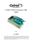
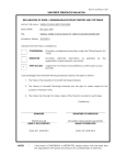
Robot Rangers
Final Report
Ben Andersen
Jennifer Berry
Graham Boechler
Andrew Setter
5/6/2011
EE41430
1
Table of Contents
1. Introduction................................................................................................................................3
1.1 Problem Description....................................................................................................3
1.2 High Level Description................................................................................................3
1.3 System Requirements..................................................................................................4
1.4 Subsystem Requirements............................................................................................4
1.5 Future Enhancement Requirements..........................................................................6
1.6 Design Results..............................................................................................................6
2. Detailed Project Description.....................................................................................................6
2.1 System Theory of Operation.......................................................................................6
2.2 System Block Diagram................................................................................................7
2.3 Detailed Operation of Marking System.....................................................................8
2.4 Detailed Operation of Detection System....................................................................8
2.5 Detailed Operation of Motor Control System...........................................................8
2.6 Detailed Operation of Wireless Communication System.......................................11
2.7 Detailed Operation of Remote Control System.......................................................15
2.8 Detailed Operation of Main Robot System..............................................................16
2.9 Detailed Operation of SPI Interface.........................................................................17
3. System Integration Testing......................................................................................................17
3.1 Mechanical Integrated Testing..................................................................................17
3.2 Software Integrated Testing......................................................................................19
3.3 Overall Requirement Satisaction .............................................................................20
4. User Manual.............................................................................................................................20
4.1 How to Install Your Product.....................................................................................20
4.2 How to Set Up Your Product.....................................................................................21
4.3 How the User Can Tell if the Product is Working...................................................21
4.4 How the User Can Troubleshoot the Product..........................................................21
5. To Market Design Changes.....................................................................................................22
6. Conclusions...............................................................................................................................22
7. Appendicies...............................................................................................................................23
2
1 Introduction
According to the UNICEF, almost 10 000 people per year are killed by land mines, most of
whom are civilians. Thousands more people lose limbs, livelihoods or loved ones1. In many
cases, the conflict is long over but the danger remains due to the difficulty of finding and
destroying the mines. Yet, destroying them is imperative for long term safety, and with over one
hundred million planted world wide it is a daunting task. Substantial action is required, but one
must disarm a hundred million deathtraps.
1.1 Problem Description
The problem is the minefield itself: a large area where a large number of explosive devices are
randomly hidden. They cannot be spotted visually, since many are buried or designed to be
difficult to detect. Disarming them personally would be extraordinarily hazardous, especially
without knowing where the mines are buried.
Our solution is a wirelessly controlled robot capable of locating the mines and marking them for
future removal. The main goal is to keep humans out of danger, and by remotely locating the
mines, disposing of them becomes much easier. Even if a mine is triggered during the marking
process, the loss of a robot is a small price to pay in comparison to that of a human life.
However, it was still important to design a robot that would not detonate any mines that were
discovered. In order to further enhance safety, it was also imperative that the mines be
accurately marked and users could operate the robot from a safe distance.
1.2 High Level Description
The Mine Detecting Robot system consists of two main parts: the robot itself and the remote
control system used to drive the robot and display information to the user. The two parts
communicate with each other through a wireless connection that sends control information to the
robot and returns sensor information to display on the remote.
The core of the robot system is a microcontroller that receives input from the metal detecting
sensors as well as from the wireless transceiver. The wireless information is processed and sent
3
to the motor driver circuits and the marking system, while any information from the metal
detectors is sent back to the remote through the wireless transceiver.
The core of the remote control system is also a microcontroller, which receives inputs from
joysticks mounted on the remote control board. Joysticks function as analog potentiometers, and
when these signals are sent through analog-to-digital converters, a digital signal that can be sent
to the robot is obtained. In order to communicate with the robot, the remote control
microcontroller also has a wireless transceiver. It sends control information, such as joystick
position and button depression, to the robot and displays information about the metal detector
array in an LED configuration on the remote controller board.
1.3 System requirements
O V E R A L L S Y S T E M!
Must maintain a wireless connection out to 50 meters
Must have a battery life of at least 30 minutes when in normal operation
Must have a battery life of at least 2 hours when in standby mode
Must detect and mark mines
Must not cause mines to detonate
1.4 Subsystem requirements
1 . 4 . 1 R E M O T E C O N T RO L S Y S T E M
Must run on battery power
Must control movement of robot through two joysticks
Movement of the robot must be able to be controlled through a physical user
input interface
Physical user interface must accept inputs based on user input and send
outputs to the robot
Physical user interface must send output (i.e. commands) to the robot via a
wireless connection
Must have LED configuration to show output of metal detectors to the user
Physical user interface must be easily understood and operated without
significant training
4
1 . 4 . 1 R E M O T E C O N T RO L S Y S T E M
Must be powered by either a battery or a power brick connection
Battery life of the unit must last at least 2 hours
Physical user interface must send commands to the robot via a wireless
connection
1.4.2 WIRELESS INTERFACE
Must be able to communicate fast enough to ensure no more than 1 second of
lag to the robot
Wireless connection must have a range of least 50 meters
1.4.3 MINE DETECTION SYSTEM
Must detect mines within 6” of each side of the robot
Spray paint mark must be at least partially over mine
Must be able to mark a large number of mines
Must not set off mines during scanning and marking process
1 . 4 . 4 M I C RO C O N T RO L L E R
Must have a separate input for each metal detector
Must have enough additional inputs to accommodate the number of sensors
needed for autonomous movement to allow for future enhancement
Must have RS232 capabilites
Must be able to generate a PWM signal
Must have SPI functionality to communicate with ATMEL RF231 chip
Must have analog to digital conversion functionality
1 . 4 . 5 RO B O T P OW E R M A N AG E M E N T
Must be capable of supplying power to robot for at least 30 minutes when in
normal operation
Must be able to supply power for at least two hours when robot is in standby
mode
5
1.4.6 MOVEMENT SYSTEM
Must be able to move in response to user input
Must be able to turn in place
Must be able to vary speeds of both treads
Must be able to move in forward and full reverse
Must be able to move on hard surfaces, grass, gravel, dirt, and slightly wet
ground
1.5 Future Enhancement Requirements
The robot would be even more effective if it did not require constant supervision and instruction
from an operator, which would be accomplished through the addition of an autonomous mode.
This would be difficult since the microcontroller would have to be able to independently sense
it’s environment and position itself over a detected mine in order to mark it.
Another future addition would be a digital copy of the locations of the mines, creating a map for
future reference. This would require significant programming to accurately track the relative
location of the robot and the location of the mines.
1.6 Design Results
The design, while meeting most of our expectations, did not meet all of them.The electronics and wireless
system, which posed the majority of the challenges we needed to overcome, were implemented
successfully. The motor system functioned the majority of the time; the robot was mobile and met design
requirements. However, we were unable to determine why the hardware would stop working when if the
robot accelerated too fast. The other disappointment was the marking system. While the mechanical
aspects were functional, it could not be operated from our main board. We believe, though are not certain,
that the battery pack could not supply sufficient current. Although we did not meet all of our
requirements, the problems were relatively minor, especially considering the complexity of our system
and what we needed to do to complete what we did.
2 Detailed project description
2.1 System theory of operation
The main goal of the robot is to remotely locate and mark landmines. To accomplish this,
the robot must preform three essential tasks: move remotely, detect mines, and mark them.
6
Firstly, for movement the robot requires a board that takes user input through joysticks, a
method of sending the information to the robot and receive information from the robot, and a
board capable of receiving information from the remote and sending back information.
Therefore, two antennas are needed and a method of encoding information so it can be sent
between them. Finally, the board must be able to control multiple motors to execute the
instructions from the remote.
The detection system must accurately locate landmines. The detectors will generate a
magnetic field and monitor changes in it to observe the location of metal. Then, the detector
must send a signal to the main microcontroller to indicate the presence of metal. To send
information to the user, the presence of metal must encoded into bits to be send over the
wireless connection, and displayed on the remote control through an indicator.
The marking system must display a permanent and highly visible mark on the ground
indicating the location of a mine. This must not be a destructive of forceful action, as that would
risk detonating the mine. Furthermore, it must be activated by the remote control, so a signal to
fire must be sent over the wireless connection and be processed by the main robot board.
2.2 System Block diagram
Figure 1. System Block Diagram
As seen in the figure above, there are two main components to the overall system - the
main robot and the remote control. The robot micocontroller takes inputs from the metal
detection system and controls the output to the marking system and the motor controller
system. The remote microcontroller takes input from the joysticks and the buttons and sends
output to the LEDs on the remote board. Both the robot and remote microcontrollers
communicated to one another wirelessly.
7
2.3 Detailed operation of Marking System
The marking system operates through a solenoid pushing the nozzle on a can of spray pain.
The solenoid is connected to a twelve volt battery pack through a MOSFET, which is controlled
by the microcontroller. When the button on the remote control is pressed, the remote sends a
signal over the wireless connection to the microcontroller. The microcontroller sends a five volt
high signal to the MOSFET, which then allows current to flow through the solenoid. The solenoid
contains a coil of wire, when current runs through it a magnetic field is generated which pushes
the pin outwards. The pin pushes a large lever, which depresses the nozzle to activate the spray
paint can. The lever gives the solenoid the necessary torque to depress the nozzle of the spray
paint can. The spray pain goes through the center of the metal detector, and marks the desired
location.
To test the mechanical operation of the marking system, the solenoid was connected directly to
a 12 volt power supply. It showed it had the necessary force to activate the spray paint can.
2.4 Detailed operation of Detection System
Each of the metal detectors is powered from a nine volt power supply on the microcontroller
board. The metal detectors contain a coil of wire, which sends out a local magnetic field. The
current in the coil responds to changes in the field due to the presence of metal, and the
detector then sends a high signal through a buffer to the microcontroller itself to indicate the
detection. Next, the microcontroller sends a signal through the wireless connection to the
remote control, which lights the appropriate LED.
To test the system, a metallic watch was moved in and out of each detector. The LED on the
remote control was observed, and the correct one illuminated.
2.5 Detailed operation of motor control system
The robot’s propulsion system consists of two motors mounted to two tread systems on
either side of the robot. The power to the motors is controlled via pulse width modulation (PWM)
which is generated by two separate motor control circuit boards (one for each motor). On the
circuit board is a full H-bridge MOSFET configuration which is controlled via the Allegro A3941
bridge driver IC. The motor control circuit boards receive their control information from the main
robot circuit board via an 8-signal cable.
The 8-signals that are connected to the main robot circuit board are:
1) The main PWM control signal
2) A reset signal to the bridge driver IC. It is held high to keep the bridge driver active.
8
3) A PWM low signal. It is held low to enable the bridge driver to use the main PWM
signal as the control input.
4) A synchronous rectification signal. It is held high to allow current to circulate back
through the bridge MOSFETs when the motors are coasting.
5) A phase signal. This signal controls which direction the motors are to rotate and is
modulated via software depending on the joystick input from the remote.
6 and 7) Two fault signals generated by the bridge driver IC. These signals are used by
the microcontroller to determine what kind of fault happened if one does occur.
8) A ground signal for referencing all of the above voltages.
The PIC18f4321 microcontroller can be configured to generate PWM output signals. The
4321 has two different PWM modules that are used to generate two unique signals for each
motor. The configuration registers for generating PWM outputs are CCP1CON and CCP2CON.
The two configuration registers determine which pin it to output the PWM signal, whether or not
the signal is active-high or active-low and finally, the two LSBs of the duty cycle register. Since
we are only using 8 bits of duty cycle resolution, these two LSBs are configured to zero.
CCP2CON is configured similarly. In order for PWM output to actually be generated, the
TIMER2 module must also be configured properly as it provides the timing for the outputed
signals. Once timer2 is configured and activated, PWM output starts. Below is the CCPxCON
and TIMER2 configuration code:
//---PWM Period--pr2 = 0xFF;
//Set the period of the PWM frequency as related to timer2
//---PWM1 (ECCP1) config registers--volatile bit [email protected] = 0;
//Single Output (P1A)
volatile bit [email protected] = 0;
//
volatile bit [email protected] = 0;
//Bit1 of duty cycle1, always 0 for 8bit resolution
volatile bit [email protected] = 0;
//Bit0 of duty cycle1, always 0 for 8bit resolution
volatile bit [email protected] = 1;
//**The next 4 bits correspond to setting
volatile bit [email protected] = 1;
//**all PWM outputs (ECCP1) to be active-high
volatile bit [email protected] = 0;
//**
volatile bit [email protected] = 0;
//**
//---PWM2 (CCP2) config registers--volatile bit [email protected] = 0;
//Bit1 of duty cycle2, always 0 for 8bit resolution
volatile bit [email protected] = 0;
//Bit0 of duty cycle2, always 0 for 8bit resolution
volatile bit [email protected] = 1;
//**The next 4 bits correspond to setting
volatile bit [email protected] = 1;
//**CCP2 into PWM mode
volatile bit [email protected] = 0;
//**
volatile bit [email protected] = 0;
//**
//---Timer2 config registers (for PWM)--volatile bit [email protected] = 0;
//**The next two bits correspond to
volatile bit [email protected] = 1;
//**the TMR2 prescalar value of 4
volatile bit [email protected] = 1;
//Enable Timer2 (Start the PWM output)
*Note that each bit of the configuration registers is declared separately to facilitate
changes that may need to be made to them in the main program flow.
The duty cycle of the PWM is essentially what determines the speed of the motor. A
100% duty cycle corresponds to full power to the motors, 50% is half power and 0% is no
power. Our design utilizes an 8 bit duty cycle register providing us with 256 different values for
9
the duty cycle of the PWM signals. The duty cycle information is generated by the software
internally after receiving input from the joysticks over the wireless connection. The joystick
values (described in more detail in the remote subsystem section) range from 0 to 255 with 127
being neutral. The values of the joystick input are mapped to the corresponding duty cycle and
phase direction by the following code:
//J1
if(received[11] > 132){
//J1 is forward
latd.3 = 1;
//Phase1 is 1 (forward)
ccpr1l = 2*(received[11] - 132); //Map the forward range of the joystick to the full
range of duty cycle1
}
else if ((received[11] > 120) && (received[11] <= 132)){ //J1 is in neutral
ccpr1l = 0;
//Duty cycle1 is 0
}
else if (received[11] <=120){
//J1 is in reverse
latd.3 = 0;
//Phase1 is 0 (reverse)
ccpr1l = 2*(121 - received[11]); //Map the reverse range of the joystick to the full
range of duty cylce1
}
//J2
if(received[12] > 132){
//J2 is forward
latd.7 = 1;
//Phase2 is 1 (forward)
ccpr2l = 2*(received[12] - 132); //Map the forward range of the joystick to the full
range of duty cycle2
}
else if ((received[12] > 120) && (received[12] <= 132)){ //J2 is in neutral
ccpr2l = 0;
//Duty cycle2 is 0
}
else if (received[12] <=120){
//J2 is in reverse
latd.7 = 0;
//Phase2 is 0 (reverse)
ccpr2l = 2*(121 - received[12]); //Map the reverse range of the joystick to the full
range of duty cylce2
}
*Note, received[12] and recieved[11] are the bytes of the incoming wireless packet that contain
the joystick information. Pins D3 and D7 are the phase direction ports for motor 1 and motor 2
respectively.
Below is the schematic of the motor control circuit boards featuring the Allegro A3941
bridge driver IC interfaced through the 8-signal PWM cable (described above). The IC fully
controls an H-bridge configuration of power MOSFETs used to control power to the motors.
10
2.6 Detailed operation of wireless communication
system
The main robot and remote boards communicate with each other via a wireless
connection using the IEEE 802.15.4 protocol. This is achieved mainly through the
implementation of the Atmel AT86RF231 wireless transceiver chip. The microcontroller
interfaces with the Atmel transceiver chip using a serial peripheral interface (SPI). The 18f4321
can be configured to output SPI compliant data. SPI consists of 4 basic signals, Master Out
Slave In (MOSI), Master In Slave Out (MISO), a clock signal and a select signal. In addition to
the four main SPI signals, the communication channel to the transceiver chip also utilizes a
sleep trigger signal, a reset signal and an interrupt signal. Below is the configuration code to
configure the microcontroller to output SPI data:
volatile bit [email protected]=0;
//Input data sampled at end of data output time
volatile bit [email protected]= 1;
//SPI clock selecte bit. Transmit occurs on
transition from Idle to active clock state.
volatile bit [email protected] = 0;
volatile bit [email protected] = 0;
is low level
//Serial Synchronous Enable bit
//Clock Polarity Select bit. Idle state for clock
volatile bit [email protected] = 0;
volatile bit [email protected] = 0;
bits
//
// SSPM<3:0>: Synchronous Serial Port Mode Select
volatile bit [email protected] = 1;
volatile bit [email protected] = 0;
// 0000 = SPI Master mode, clock = FOSC/64
//
With this code implemented, the next step is to write your information you wish to
transmit over SPI to the sspbuf register. Below is a function written to send data out over the
SPI interface and return the data received after the transmission:
char SPIsend(char sent_byte){
char returned_byte;
11
sspif = 0;
//Interrupt flag set low
sspbuf = sent_byte;
//Load buff with data to send
while(sspif == 0);
//Wait for interrupt indicating send complete
returned_byte = sspbuf;
//After interrupt, buffer contained returned data
sspif = 0;
//Clear interrupt flag again for good measure
return returned_byte; //Function returns received information
}
After proper data transmission has been established using the SPI interface, the next
step is write data to the appropriate registers on the Atmel wireless transceiver chip to enable it
for radio transmission. In the software, several functions were written to simplify and enhance
the code readability. The first function is used to write to the transmit state register on the Atmel
chip. The transmit state register holds the state variable for the transceiver's internal state
machine. It must be set accordingly in order for the transceiver to transmit properly.
void set_trx_state(char cmd){
at_sel = 0;
SPIsend(0b11000010);
SPIsend(cmd);
at_sel = 1;
return;
}
//We want to write to register 0x02 (TRX_STATE)
The next function writes to the IRQ_MASK register which controls which interrupts are
going to be active on the wireless transceiver chip. For our design, we only wish to use the
IRQ_3 interrupt which signals when the frame buffer has finished receiving an incoming packet
and is ready to read. The following functions set (or clear) that register accordingly.
void enable_irq_3(void){
at_sel = 0;
SPIsend(0b11001110);
SPIsend(0b00001000);
at_sel = 1;
return;
}
void disable_irq_3(void){
at_sel = 0;
SPIsend(0b11001110);
SPIsend(0b00000000);
at_sel = 1;
return;
}
//We want to write to register 0x0E (IRQ_MASK)
//Setting bit[3] = enable IRQ_3 (TRX_END)
//We want to write to register 0x0E (IRQ_MASK)
//clear bit[3] = disable IRQ_3 (TRX_END)
Once the interrupts have been properly enabled, you must select a channel to transmit
on by setting the appropriate register. The following function performs that task.
void select_channel(char channel){
at_sel = 0;
SPIsend(0b11001000);
SPIsend(channel);
at_sel = 1;
return;
}
//Command byte for Register Write Access
//Channel select byte
12
Two function were also written to read and write from the frame buffer on the Atmel
transciever chip. These two functions are significantly more complicated than the previous
because the frame buffer must be constructed according to the IEEE 802.15.4 specifications.
The following function writes information to the frame buffer and completes the preparation
necessary needed for transmission.
char write_frame(char* data, char size, char seq){
char received;
at_sel = 0;
SPIsend(0b01100000);
//Frame write access command byte
SPIsend(size + 13);
//PHY header (PHR) with MSB reserved - frame length
SPIsend(0b00000000);
//Reserved[7], IntraPAN[6], ACK Request[5], Frame Pending
[4], Security enabled[3], Type[2:0]
SPIsend(0b10001000);
//Source addressing mode[15:14], Frame version[13:12],
Destination addressing mode[11:10], Reserved[9:8]
SPIsend(seq);
//Sequence number
SPIsend(0b11001100);
//Destination PAN ID = 0xCCCC (Remote)
SPIsend(0b11001100);
SPIsend(0b11011101);
//Destination address = 0xDDDD (Remote)
SPIsend(0b11011101);
SPIsend(0b10101010);
//Source PAN ID = 0xAAAA (Robot)
SPIsend(0b10101010);
SPIsend(0b10111011);
//Source address = 0xBBBB (Robot)
SPIsend(0b10111011);
for (int i=0;i<size;i++){
received = SPIsend(data[i]); //Data payload
}
SPIsend(0b00000000);
//Frame check sequence (FCS) 2 bytes
SPIsend(0b00000000);
at_sel = 1;
return received;
}
Note that the destination and source PAN ID and addresses are hard coded because the
transmission will only occur between the robot and remote. Reading from the frame register is
similar to writing to it. The following function performs that task and returns the frame buffer as
an array of chars (bytes).
char* read_frame(void){
char read;
char store[128] = 0;
char frame_length;
at_sel = 0;
SPIsend(0b00100000);
frame_length = SPIsend(0b00000000);
buffer
//Command byte for Frame buffer read access
//Read in PHR byte stating how many bytes are in the
for (int i=0; i < (frame_length + 1) ; i++){
(last byte is lqi)
if(i>127) i = 127;
read = SPIsend(0b00000000);
store[i] = read;
//Iterate through frame_length+1
//Read in the one-byte message
//Store the received byte
}
at_sel = 1;
13
read_register(15);
read has finished.
//Reading register 15 signals to the Atmel chip that the
return store;
}
The next function is used to consolidate the steps required for wireless data
transmission into one, easy to use, easy to read function.
void transmit(char* data, char size, char seq, char channel){
select_channel(channel);
set_trx_state(8);
//0x08 = TX_OFF
set_trx_state(9);
//0x09 = PLL_ON (transmission
on)
write_frame(data, size, seq);
set_trx_state(2);
//0x02 = TX_START (start
transmission)
return;
}
The receive function is similar to the transmit function except that it puts the chip into a
state to receive. The software must then wait for the interrupt signal on IRQ signaling that the
buffer is full and ready to read, and then the frame buffer can be read and the packet
information extracted.
void receive(char channel){
select_channel(channel);
set_trx_state(8);
set_trx_state(6);
and continuously check for frames)
//0x08 = TX_OFF
//0x06 = RX_ON (enter state RX_ON
return;
}
For the complete robot and remote transmission system, the robot and remote takes
turns sending data packets out to the other and waiting for a return packet. This is accomplished
using the code below:
disable_irq_3();
transmit(to_send,3,sequence,CHAN);
sequence = sequence + 1;
delay_ms(1);
enable_irq_3();
receive(CHAN);
readytoread);
received = read_frame();
readytoread = 0;
while(!
Note the array to_send contains the information gathered from the sensors on the robot/
remote. The delay is added after the transmission sequence before enabling the interrupt to
ensure a false interrupt is not sent while the transceiver chip is still transmitting the data from
14
the previous command. Since the program flow continuously cycles through this code, the robot
and remote will continuously be exchanging and updating each other’s information.
On the remote side, code was added to count the amount of time that has elapsed since
it sent it’s last packet. If it waits for a response from the robot for too long, it assumes that the
robot did not receive the packet and re-sends the data and begins to wait for a response again.
disable_irq_3();
transmit(to_send,3,sequence,CHAN);
//Transmit the remote info on the value of CHAN
sequence = sequence + 1;
delay_ms(1);
enable_irq_3();
receive(CHAN);
//Put the Atmel chip in a state to receive data
while(!readytoread){
hangcounter = hangcounter + 1;
if(hangcounter > 100000){
//If you've waited to long, break out and retransmit
failedtoconnect = 1;
readytoread = 1;
}
}
//Wait here for a response from the robot
hangcounter = 0;
received = read_frame();
//Read the data from the robot
readytoread = 0;
100 ms delays were also added in the main program loop of both the robot and remote
to prevent the over-transmission of wireless packets. With the system updating itself about 10
times a second, there is still plenty of resolution in terms of data collection and lag time. Also
power consumption is reduced by limiting the rate at which wireless packets are sent.
2.7 Detailed operation of remote control system
The remote control system, just like the main robot system, has 3 main functions that it
performs. It a) gathers information from it’s sensors and organizes them into an array of bytes,
b) transmits the array containing the sensor information to the robot and waits for a reply and c)
updates the LEDs with the information received from the robot. This cycles continuously in an
infinite loop.
The first, and simplest sensor collection is reading the state of the button press on the
control board. The button is to signal when the marking system should be activated. This is
achieved by simply setting the I/O pin in the microcontroller (that the button is connected to) as
an input and reading the state of the input pin. The button circuit is configured to be ground
when the button is not pressed and a high voltage when the button is pressed.
The joystick (potentiometer) sensor reading is more involved because it requires an
analog to digital (A/D) conversion. There are three registers associated with A/D conversion on
the 18f4321 microcontroller. They are ADCON0, ADCON1, and ADCON2. ADCON0 is
responsible for selecting which analog input you wish to convert and also contains the enable
and start bits for A/D conversion. ADCON1 is responsible for setting which input pins are
configured as analog input and which are configured as digital. ADCON2 is used to configure
15
several aspects regarding the output of the conversion including setting the acquisition time and
setting the A/D conversion clock. The software then sets the conversion start bit and waits for
the bit to go low. The microcontroller will set the bit low when the conversion process is finished
and is ready to be read. The value of the conversion is then read and stored into the array that
is to be transmitted. After the first conversion, a short delay is added before the the next analog
input is selected (the second joystick) and the conversion process starts again and the second
value is loaded into the the array. The following code accomplishes this task.
volatile
volatile
volatile
volatile
bit
bit
bit
bit
volatile
result
volatile
volatile
volatile
volatile
volatile
volatile
bit [email protected] = 0;
bit
bit
bit
bit
bit
bit
[email protected]
[email protected]
[email protected]
[email protected]
[email protected]
[email protected]
[email protected]
[email protected]
[email protected]
[email protected]
=
=
=
=
0;
0;
0;
0;
=
=
=
=
=
=
1;
1;
1;
0;
0;
1;
//Select channel 0 (J1)
//
//
//
//adresh will contain the 8 MSBs of the
//
//
//
//
//
//
The next 3 bits set the A/D aquistion time to
20 * Tad (Longest possible aquisition time)
The next 3 bits set the A/D conversion clock
Tosc * 8
volatile bit [email protected] = 1;
//Turn on the A/D converter module
volatile bit [email protected] = 1;
//Start the aquistion/conversion process
while(go == 1);
//Wait here until the A/D coversion is done
to_send[0] = adresh;
//Load up the to_send array with the first joystick value
delay_us(20);
//Wait some time before starting the next aquisition on J2
chs3
chs2
chs1
chs0
adon
=
=
=
=
=
0;
0;
0;
1;
1;
go = 1;
while(go == 1);
to_send[1] = adresh;
delay_us(20);
//Select channel 1 (J2)
//
//
//
//Turn on the A/D converter module
//Start the aquistion/conversion process
//Wait here until the A/D coversion is done
//Load up the to_send array with the second joystick value
Now that the sensor information has been gathered, the data is wirelessly transmitted to
the robot (see the wireless subsystem description section) and the information from the robot is
received. The received information is then directly extracted and used to illuminate the LEDs on
the control board. This is accomplished by setting the LED pins to digital outputs and setting
their value high. The output pin is then wired through the LED and a current limiting resistor and
connected to ground. This code is on an infinite loop and will continue to update the information
until either the robot or the remote is turned off.
2.8 Detailed operation of main robot system
The main robot system is similar to the remote control system such that it has to
accomplish 3 main tasks. It collects the metal detector input information through the reading of a
16
digital input port on the microcontroller. Since the metal detector output is around 9 volts, the
signal is run through a unity gain amplifier/buffer that uses an op-amp circuit that can reduce
input voltages down to the system voltage of 5 volts. The buffer also isolates the metal detection
system electrically so that the microcontroller will not draw any current from the metal detector
and interfere with its function. The state of each metal detector is gathered and organized into
an array that is to be transmitted to the remote (see the wireless subsystem description section
for more information about the transmission process). After the transmission of the sensor data
and the reception of the packet from the remote, the received information is used to update the
PWM duty cycle and phase direction (see the motor control subsystem description) as well as to
drive the gate signal of the solenoid MOSFET (see the marking subsystem description). This
software continues on an infinite loop and will continue until either the robot or the remote is
turned off.
2.9 Detailed Operation of SPI Interface
SPI (Serial Peripheral Interface) is the synchronous serial data link used to allow the
microcontrollers to communicate with the ATMEL transceiver chips. The microcontroller
selected allows for SPI communication, and thus the microcontroller simply needed to be
configured to allow data to be sent between the two chips. The 18f4321 can be configured to
output SPI compliant data. SPI consists of 4 basic signals, Master Out Slave In (MOSI), Master
In Slave Out (MISO), a clock signal and a select signal. In addition to the four main SPI signals,
the communication channel to the transceiver chip also utilizes a sleep trigger signal, a reset
signal and an interrupt signal. Once this setup was done, data could be successfully sent
between the parts, allowing for the basic underlying structure that made the wireless
communication successful.
3 System Integration Testing
Through our design process, testing of our designs led to a variety of alterations and
improvements upon our initial plan to try to satisfy our system requirements. The following is an
overview of the testing process and the adaptations of our design during the development of our
robot.
3.1 Mechanical Integrated Testing
The system requirements of our robot that were of greatest concern to the mechanical
systems in our robot were the ability of the robot to traverse a field, the ability to detect mines
within the sweep of the robot, and the ability to mark those mines with our marking system. In
order to test these requirements and ensure that we were able to fulfill them we needed to test
each of the following components of the robot: the treads, the motor, the mounting setup for the
marking system, the frame layout, and the design of the joystick enclosure.
17
In order to test the treads they were first mounted to the frame and connected to the
motors. They were then tested by driving the robot around on a smooth surface and then on
grassy surface outside to mimic the terrain of a mine field. When we first drove the treads with
the load of the robot we noticed several issues that needed to be monitored for our setup to
work properly. First, we found that the tension on the treads must be set properly in order for
the robot to be able to drive at all. Setting the tension too high puts stress on the gearbox and
prevents the treads from turning at all, while setting the tension to low causes the treads to bend
around the wheel connected to the gear box. This bending causes adjacent treads to hit each
and either results in a loud clicking noise while the robot is moving or a lock up in the treads
which prevents the robot from moving at all. Setting the tension correctly simply required
inserting the proper number of links.
The testing of the motor system was done initially in early a December and again once
the motors we chose for our final design arrived in the spring. Initially we tested the proper
function of the H-bridge circuitry and the allegro chip we selected in December using motors
similar to the those we would use in our final design which were provided to us in the storage
room. These motors we run without a comparable load to the that of the final robot; however,
they demonstrated the proper functioning of our circuitry. When our final motor system was
assembled, testing was done by driving the robot around on both a smooth surface and on
grass at variable speeds. Our initial testing showed an issue with a power surge related to
rapidly increasing the speed of the motors. We found that slamming the joysticks forward
caused the robot board with the microcontroller to fault, and we believed this to be the result of
a power spike from ramping up the motors too rapidly. We decided to remedy this problem by
running the motors and the robot board of separate power supplies. We altered our design so
that the motors were supplied by the main 12V battery while the robot board was powered at
12V by a AA battery pack. This was unable to prevent hangs in the robot board, and so we tried
as a second solution to add an additional button to the joystick which when pressed would be
able to reset the robot board and allow the robot to continue to function.
The testing of the marking system required ensuring the ability of the solenoid to fire with
the circuitry designed on the robot board and the ability of the solenoid to release paint from the
spray can which would mark the position of a detected mine. Our initial testing of the system
found that the FDD3N40 MOSFET chosen four initial design, which had an maximum amperage
rating of 2A was unsuitable for activating the solenoid. We determined that the button signal
was properly reaching the gate, and so the solenoid was unable to flow current to the solenoid.
To redesign the system we connected a 30 amp maximum MOSFET from the storage room,
which was able to flow current from the robot board to the solenoid. Testing of the spray can,
however, revealed a separate issue with our initial design. When the solenoid chosen was
directly connected to our robot battery it was able to generate enough force to depress the
spray can button and release paint; however, when supplied by the robot board it was unable to
generate a sufficient force. In order to generate a larger force on the spray paint can, we
installed a 1.5’ lever on the top of the robot so that the solenoid would be mounted to the top of
the lever and the lever would increase the force of the solenoid on the button. This system
ultimately proved to be inadequate for our final design as the position of the lever relative to the
head of the button had to be precisely monitored for the system to work when powered from the
board. As a result the marking system was not able to be demonstrated in our final design.
The testing of the frame design included testing the ability of the mounted metal
detectors to be able to detect mines across the full sweep of the robot and the ability of the
frame to securely mount each of the robot components. The initial testing of the metal detectors
18
involved experimentally determining the range of their detecting radius so that we could
determine what orientation they should be placed in so that there would be no “dead zones”, or
areas underneath the robot where a mine could be present but no detected, and so that they
would not interfere with each other or any other robot components and only detect external
metal. Testing resulted in finding a triangular position which satisfied all of the requirements and
which determined the height at which the spray paint can had to be mounted above the rear
metal detector. Testing of the frame apart from the metal detectors involved ensuring that space
was available for each component could be securely mounted and that the material chosen
would be sufficiently sturdy for our application. Testing confirmed our initial design in both of
these areas.
Our final mechanical system to be tested was the joystick and resulting joystick
enclosure. Our initial plan for the joystick was to use the joystick board designed by the
mechanical engineers as had been recommended to us by Prof. Schafer. Upon receiving the
board we found that it would not be sufficient for our design as we needed additional circuitry in
place for both our buttons and our landmine marking LEDs. This led to the design of a joystick
enclose which had used the joysticks from the mechanical engineers board, but which had both
buttons and the landmine marking LEDs custom mounted and connected to additional circuitry
in a breadboard.
3.2 Software Integrated Testing
Testing of the software required testing the PWM software, testing the SPI connection
between the microcontroller and the Atmel chip, and testing the wireless transmission to ensure
that all data was being properly sent and received by both the control board and the robot
board.
The PWM software was initially tested using our kit board and motors supplied by the
storage room. Testing revealed that our first design of the PWM code was causing either a
negative or positive signal to be constantly sent to the motor, so that at rest the motor was being
sent a positive signal half of the time and a negative signal half of the time. This was a highly
inefficient use our battery and putting undue strain on the motors, therefore, the code was
modified so that in each direction either a pulse was being sent to move the motor or no signal
was being sent.
In order to be able to set up the wireless connection between the remote board and the
robot board we had to first ensure that we were able to properly communicate between our
microcontroller and the ATMEL wireless chip using SPI. Testing of our SPI connection involved
writing to registers in the ATMEL chip and then reading them back to ensure that data was
properly being sent and received. For testing purposes, information being sent and received on
each pin was monitored by connecting the pins to the USB Logic Analyzer.
Testing of the full wireless software involved testing our code’s ability to properly send
and receive packets of information containing the position of both the buttons and the
potentiometers on the remote board and the metal detector signals from the robot. Additionally,
these features needed to function out to the 50m range specified in our system requirements.
In order to test the information being sent by the wireless system, we connected both the packet
sender and packet sniffer boards provided to us by Professor Schafer. The sniffer board
allowed us to read the data being sent by our system, and the sender board allowed us to send
a known set of data with code we knew was using the proper 802.15.4 protocol. Our initial
19
editions of the wireless software showed that when reading data we were not handling the
interrupts generated by the ATMEL chip properly. Our code was modified so that our boards
began to read the frames once the interrupt was generated that signaled that the entire frame
had been sent. During testing of the wireless we also noticed an issue whereby the remote and
robot boards periodically would hang and stop transmitting data to the other boards. This issue
was addressed by adding in while loops into the code so that the remote board continually
transmits data 10 times per second while the robot board waits for the reception of the remote
board data before sending the metal detector signals. Testing for the wireless range was also
conducted by distancing the boards and confirming functionality.
3.3 Overall Requirement Satisfaction
The movement system is demonstrated to meet requirements through the operation of
the treads. If the threads can be moved with varying speed and direction, the motor system is
fully functional. If the robot can preform these while in outdoor terrain, then the motor selection
was accurate and the robot meets all movement requirements.
By operating the robot from a reasonable distance by the remote, the entire software
system is shown to be functional. To move the robot, the input must be received through the
joysticks, encoded and sent to the robot, and decoded and implemented by the motors. So long
as lag is not observed, the system is satisfactory.
The detection system can be directly tested by placing metal in range of the detectors,
and observing if the appropriate indicator lights up. The metal can be moved to determine the
range of the detectors, and they were calibrated to meet requirements.
The detection system did not meet requirements, but operated when connected to an
external supply. Although it could not be operated on the robot, it passed the mechanical
requirements; it just could not operated through the main board.
Through our demo, the robot stayed in standby mode for approximately four hours with a
negligible drop in battery voltage, exceeding power management requirements, even with
intermittent activity. Furthermore, it functioned through all tests; while not directly tested it meets
the thirty minute activity requirements.
4 Users Manual
4.1 How to install your product
Your robotic landmine detector comes fully assembled; you only need to install the battery. First,
ensure the battery is fully charged using a voltmeter, then attach the positive and negative leads
to the red and black terminals of the battery respectively. Attach a nine volt battery to the remote
control, and the system is ready to go.
20
4.2 How to set up your product
Remove the spray paint can, and shake vigorously. This ensures that the markings will be as
visible as possible, and should be performed before every use of the robot. Move the switch on
the main board inside the robot to the on position. Then, hit the reset button on the main board,
and the reset button on the remote control. You robot is now ready to begin sweeping the
minefield.
4.3 How the user can tell if the product is working
To move the robot, push the joysticks in the desired directions. Pushing both forward on both
will move the robot forward, and pulling both will move the robot backwards. Pushing one stick
forward and one backwards will rotate the robot in place, for example pushing the left stick
forward and pulling the right stick backwards will rotate the robot clockwise. Pull the left stick
and push the right to rotate counter clockwise. If the robot performs all of these motions, the
motors and treads are functioning.
To test the detection system, take a large metal object such as a watch or screwdriver and move
it back and forth under each metal detector. The corresponding LED on the remote control
should blink on and off.
To test the marking system, press and release the mark button on the remote. If the lever
pushes the can and it sprays paint onto the ground, the system is functional.
4.4 How the user can troubleshoot the product
If the robot is not moving correctly:
First, try resetting the motor boards using the button on the remote control. If this does not solve
the problem, manually reset the remote control and the board inside the robot. If the robot still
does not move, check both treads and ensure they are moving freely and attached properly. If
none of these resolve the problem, try charging or replacing the remote and main batteries.
If the metal detection system does not activate, ensure no wires have come loose within the
robot. If there is no break in the wiring, and the main and remote batteries are functional, then
the faulty metal detector needs to be replaced.
If a metal detector fires continuously even when no metal is resent, reduce the sensitivity of the
detector using a small screwdriver by turning the threshold dial on the side of the detector. It
appears as a screw inside a hole along the side of the detector. Do not loosen the screws on the
bottom of the detectors; this will cause them to fall apart.
If the marking system does not function, ensure the can has not depleted after repeated use;
replace it if necessary. If this does not solve the problem, ensure the pin has not fallen out of the
21
solenoid, and the lever is making contact with the nozzle. Finally, check the voltage of the main
battery. If it drops too low, the solenoid will not be able to activate the spray can. Recharge the
battery.
5 To-Market Design Changes
Before going to market, several design changes would be necessary in order to make
our solution a more viable option for our customers. The construction of the frame would be
weather and water proofed in order to provide greater durability in multiple environments that
may contain land mines. The design of the frame itself would be more compact, but still allow
for an increased range in detection so that fewer passes are needed over a given search area.
A higher ground clearance would allow for the ability to search areas with more rugged terrains.
Another area of focus would be the user interface with the remote control and how the
user controls these interactions with the robot. This would include an increase in the wireless
communication range so as to keep people further from data. Also, improved power
management and voltage monitors would inform the user when the robot’s battery needs to be
recharged.
In terms of the marking system, instead of using a solenoid to activate the spray paint
can nozzle, a solution using either a DC or stepper motor would be designed and implemented.
This would solve the problem of having a large lever on the back of the robot that may cause
the robot to tip over. It would still be a design challenge to assure that the motor would be able
to produce enough torque to depress the paint can nozzle, but it is another option that should be
explored.
6 Conclusions
The problem presented by landmine detection is a serious issue which requires a
sophisticated system to properly be properly addressed. While our system is able to be
improved in several aspects in order to completely satisfy as a solution to landmine detection
and marking, it offers a prototype which demonstrates at a basic level the features which a
commercial solution would use. Our system is wirelessly controlled by a remotre board which
can be operated out to a safe distances of 50m. With this wireless control the robot is able to
scan the minefield and identify to the operator the location of landmines by transmitting the
singals of metal detectors mounted on to the robot to the remote and using them to light up
landmine identifying LEDs. Our system lacked the budget and sophistication to demonstrate a
robot which could selectively scan for landmines among other metallic objects or which could
traverse any terrain in which landmines might be present; however, we were able to
demonstrate a system which was able to traverse natural terrain similar to what might be
present in a field and which could identify underlying metallic objects.
Bringing our system to commercial grade would require addressing several issues within
our design and upgrading several of the robotic components. Among these necessary
22
improvements, the glitch that causes the robot board to hang when power to the motors is either
rapidly applied or applied for a long duration of time must be fixed. The tread system must also
be upgraded by either installing larger, more durable treads with larger ground clearance or an
all terrain wheel system. The marking system in a commercial system must be upgraded to
provide a functioning, clearly identifiable marking of detected mines. Additionally, the use of
more high end metal detectors would allow for a more extensive and selective detecting of
landmines. Overall, however, we were able to demonstrate the functioning of a prototype
system which shows a potential solution for addressing a serious issue whihc effects people in
countries the world over.
7 Appendices
Motor Controller Board Schematic
Motor Controller Board Layout
23
Robot Control and Remote Control Board Schematic
24
Robot Control and Remote Control Board Layout
25
/*
____
__
__
____
/\ _`\
/\ \
/\ \__
/\ _`\
\ \ \L\ \
___\ \ \____
___\ \ ,_\
\ \ \L\ \
__
___
__
__ _ __ ____
\ \ , /
/ __`\ \ '__`\ / __`\ \ \/
\ \ , /
/'__`\ /' _ `\ /'_ `\ /'__`\\`'__\',__\
\ \ \\ \ /\ \L\ \ \ \L\ \\ \L\ \ \ \_
\ \ \\ \ /\ \L\.\_/\ \/\ \/\ \L\ \/\ __/ \ \/\__, `\
\ \_\ \_\ \____/\ \_,__/ \____/\ \__\
\ \_\ \_\ \__/.\_\ \_\ \_\ \____ \ \____\ \_\/\____/
\/_/\/ /\/___/ \/___/ \/___/ \/__/
\/_/\/ /\/__/\/_/\/_/\/_/\/___L\ \/____/\/_/\/___/
/\____/
\_/__/
Team Robot Rangers
*/
/*
Version 1.2
Main Robot
5/2/11
*/
#include <system.h>
#define CHAN 11
#pragma
#pragma
#pragma
#pragma
DATA
DATA
DATA
DATA
_CONFIG1H,
_CONFIG2H,
_CONFIG4L,
_CONFIG3H,
_OSC_INTIO2_1H
_WDT_OFF_2H
_LVP_OFF_4L & _XINST_OFF_4L
_MCLRE_ON_3H
#pragma CLOCK_FREQ 8000000
//---Global variables--volatile bit [email protected];
volatile bit [email protected];
volatile bit [email protected];
volatile bit [email protected];
volatile bit [email protected];
volatile bit [email protected];
volatile bit [email protected];
volatile bit [email protected];
bool readytoread = 0;
//Atmel Chip select
//Atmel Chip reset
//Atmel Chip sleep set high to make not sleep
//MD1 volatile bit
//MD2 volatile bit
//MD3 volatile bit
//SPI interupt flag, indicates SPI send complete
//INT0 interupt flag (from port b0) that is connected to IRQ on the Atmel
void interrupt(void){
volatile bit [email protected];
if(sspif == 1)
sspif = 0;
else if(int0if == 1){
int0if = 0;
readytoread = 1;
}
}
char SPIsend(char sent_byte){
char returned_byte;
sspif = 0;
sspbuf = sent_byte;
while(sspif == 0);
returned_byte = sspbuf;
sspif = 0;
return returned_byte;
//Interrupt flag set low
//Load buff with data to send
//Wait for interuput indicating send complete
//After interrupt, buffer contained returned data
//Clear interupt flag again for good measure
//Function returns recieved information
}
char read_register(char reg){
char tosend = 0b10000000;
char ans;
at_sel = 0;
tosend = tosend | reg;
SPIsend(tosend);
ans = SPIsend(0b00000000);
at_sel = 1;
return ans;
}
//Start off with the read command
//OR the read command with the register we want to read
//Send gibberish to read the data in the register
char write_frame(char* data, char size, char seq){
char received;
at_sel = 0;
SPIsend(0b01100000);
//Frame write access command byte
SPIsend(size + 13);
//PHY header (PHR) with MSB reserved - frame length
SPIsend(0b00000000);
[3], Type[2:0]
SPIsend(0b10001000);
mode[11:10], Reserved[9:8]
SPIsend(seq);
//Reserved[7], IntraPAN[6], ACK Request[5], Frame Pending[4], Security enabled
//Source addressing mode[15:14], Frame version[13:12], Destination addressing
//Sequence number
//Addressing fields go here if we the set the SAM and the DAM accordingly
SPIsend(0b11001100);
//Destination PAN ID = 0xCCCC (Remote)
SPIsend(0b11001100);
SPIsend(0b11011101);
//Destination address = 0xDDDD (Remote)
SPIsend(0b11011101);
SPIsend(0b10101010);
//Source PAN ID = 0xAAAA (Robot)
SPIsend(0b10101010);
SPIsend(0b10111011);
//Source address = 0xBBBB (Robot)
SPIsend(0b10111011);
for (int i=0;i<size;i++){
received = SPIsend(data[i]);
}
//Data payload
SPIsend(0b00000000);
SPIsend(0b00000000);
//Frame check sequence (FCS) 2 bytes
at_sel = 1;
return received;
}
char* read_frame(void){
char read;
char store[128] = 0;
char frame_length;
at_sel = 0;
SPIsend(0b00100000);
frame_length = SPIsend(0b00000000);
//LCD_bin(frame_length);
for (int i=0; i < (frame_length + 1) ; i++){
if(i>127) i = 127;
read = SPIsend(0b00000000);
store[i] = read;
}
//Command byte for Frame buffer read access
//Read in PHR byte stating how many bytes are in the buffer
//Iterate through frame_length+1 (last byte is lqi)
//Read in the one-byte message
//Store the received byte
at_sel = 1;
read_register(15);
return store;
}
char check_trx_status(void){
char ans;
at_sel = 0;
SPIsend(0b10000001);
ans = SPIsend(0b00000000);
at_sel = 1;
return ans;
}
void set_trx_state(char cmd){
at_sel = 0;
SPIsend(0b11000010);
SPIsend(cmd);
at_sel = 1;
return;
}
void enable_irq_3(void){
at_sel = 0;
SPIsend(0b11001110);
SPIsend(0b00001000);
at_sel = 1;
return;
}
void disable_irq_3(void){
//We want to read register 0x01 (TRX_STATUS)
//Send gibberish and return the value of the register
//We want to write to register 0x02 (TRX_STATE)
//We want to write to register 0x0E (IRQ_MASK)
//Setting bit[3] = enable IRQ_3 (TRX_END)
at_sel = 0;
SPIsend(0b11001110);
SPIsend(0b00000000);
at_sel = 1;
return;
//We want to write to register 0x0E (IRQ_MASK)
//clear bit[3] = disable IRQ_3 (TRX_END)
}
void select_channel(char channel){
at_sel = 0;
SPIsend(0b11001000);
SPIsend(channel);
at_sel = 1;
return;
}
//Command byte for Register Write Access
//Channel select byte
void transmit(char* data, char size, char seq, char channel){
select_channel(channel);
set_trx_state(8);
//0x08 = TX_OFF (we have to go to this state first after a power on) pg.
set_trx_state(9);
//0x09 = PLL_ON (transmission on)
33
write_frame(data, size, seq);
set_trx_state(2);
//0x02 = TX_START
return;
}
void receive(char channel){
select_channel(channel);
set_trx_state(8);
//0x08 = TX_OFF (we have to go to this state first after a power on) pg.
set_trx_state(6);
//0x06 = RX_ON
33
return;
}
//---Wireless/SPI pins--// /SEL =
B4 out
// MOSI =
C5 out
// MISO =
C4 in
// SCLK =
C3 out
// IRQ =
B0 in
// SLP_TR = A3 out
// /RST =
B5 out
//---PWM pins--// PWM1 =
C2
// Reset1 = D0 out
// PWML1 =
D1
// SR1 =
D2
// Phase1 = D3 out
// FF11 =
B1
// FF21 =
B2
//
//
//
//
//
//
//
out (ECCP1)
out
out
in
in
PWM2 =
C1 out (CCP2)
Reset2 = D4 out
PWML2 =
D5 out
SR2 =
D6 out
Phase2 = D7 out
FF12 =
B3 in
FF22 =
B6 in
//---Metal Detector Pins--// MD1 =
E0 in
// MD2 =
E1 in
// MD3 =
E2 in
//---Solenoid Pin--// Sol =
A7 out
//---Level Shifter output enable--// OE =
A2 out
void main(void){
char *received;
(enter state RX_ON and continuously check for frames)
char to_send[3];
char sequence = 0;
//--Oscillator config registers--volatile bit [email protected] = 1;
volatile bit [email protected] = 1;
volatile bit [email protected] = 1;
volatile bit [email protected] = 1;
//**The next 3 bits set the internal oscillator frequency to 8 Mhz
//**
//**
//Use the internal oscillator block as the system clock
//---Wirless/SPI port directions--volatile bit [email protected] = 0;
volatile bit [email protected] = 1;
volatile bit [email protected] = 0;
volatile bit [email protected] = 0;
volatile bit [email protected] = 1;
volatile bit [email protected] = 0;
volatile bit [email protected] = 0;
//
//
//
//
//
//
//
//---Metal Detector port directions--volatile bit [email protected] = 1;
volatile bit [email protected] = 1;
volatile bit [email protected] = 1;
//MD1 in
//MD2 in
//MD3 in
//---Solenoid MOSFET gate port direction--volatile bit [email protected] = 0;
//Sol out
MOSI out
MISO in
SCLK out
/SEL out
IRQ in
SLP_TR out
/RST out
//---Level Shifter output enable port direction--volatile bit [email protected] = 0;
//OE out
//---Init the solenoid MOSFET gate signal to zero--lata.7 = 0;
//Solenoid MOSFET = off
//---Init the Level Shifter output enable--lata.2 = 1;
//OE high (stays this way)
//---A/D converter config register--adcon1 = 0x0F;
//---Reset Atmel part before setting SPI registers--at_rst = 0;
delay_ms( 5 );
at_rst = 1;
//---SPI
volatile
volatile
clock state.
volatile
volatile
volatile
volatile
volatile
volatile
config registers--bit [email protected]=0;
bit [email protected]= 1;
//Input data sampled at end of data output time
//SPI clock selecte bit. Transmit occurs on transition from Idle to active
bit
bit
bit
bit
bit
bit
//Serial Synchronous Enable bit
//Clock Polarity Select bit. Idle state for clock is low level
//
// SSPM<3:0>: Synchronous Serial Port Mode Select bits
// 0000 = SPI Master mode, clock = FOSC/64
//
[email protected]
[email protected] =
[email protected]
[email protected]
[email protected]
[email protected]
= 0;
0;
= 0;
= 0;
= 1;
= 0;
//---PWM Period--pr2 = 0xFF;
//---Set
volatile
volatile
volatile
volatile
volatile
volatile
volatile
PWM
bit
bit
bit
bit
bit
bit
bit
port [email protected] = 0;
[email protected] = 0;
[email protected] = 0;
[email protected] = 0;
[email protected] = 0;
[email protected] = 1;
[email protected] = 1;
//
//
//
//
//
//
//
PWM1 =
C2 out (ECCP1)
Reset1 = D0 out
PWML1 =
D1 out
SR1 =
D2 out
Phase1 = D3 out
FF11 =
B1 in
FF21 =
B2 in
volatile
volatile
volatile
volatile
volatile
volatile
volatile
bit
bit
bit
bit
bit
bit
bit
[email protected]
[email protected]
[email protected]
[email protected]
[email protected]
[email protected]
[email protected]
//
//
//
//
//
//
//
PWM2 =
C1 out (CCP2)
Reset2 = D4 out
PWML2 =
D5 out
SR2 =
D6 out
Phase2 = D7 out
FF12 =
B3 in
FF22 =
B6 in
//---Init PWM signals--ccpr1l = 0;
latd.0 = 1;
latd.1 = 1;
latd.2 = 1;
latd.3 = 0;
=
=
=
=
=
=
=
0;
0;
0;
0;
0;
1;
1;
//Duty cycle1 initialized to 0
//Reset1 is high (stays this way)
//PWML1 is high (stays this way)
//SR1 is high (stays this way)
//Phase1 is initialized to 0
ccpr2l
latd.4
latd.5
latd.6
latd.7
=
=
=
=
=
0;
1;
1;
1;
0;
//Duty cycle2 initialized to 0
//Reset2 is high (stays this way)
//PWML2 is high (stays this way)
//SR2 is high (stays this way)
//Phase2 is initialized to 0
//---PWM1 (ECCP1) config registers--volatile bit [email protected] = 0;
volatile bit [email protected] = 0;
volatile bit [email protected] = 0;
volatile bit [email protected] = 0;
volatile bit [email protected] = 1;
volatile bit [email protected] = 1;
volatile bit [email protected] = 0;
volatile bit [email protected] = 0;
//Single Output (P1A)
//
//Bit1 of duty cycle1, always 0 for 8bit resolution
//Bit0 of duty cycle1, always 0 for 8bit resolution
//**The next 4 bits correspond to setting
//**all PWM outputs (ECCP1) to be active-high
//**
//**
//---PWM2 (CCP2) config registers--volatile bit [email protected] = 0;
volatile bit [email protected] = 0;
volatile bit [email protected] = 1;
volatile bit [email protected] = 1;
volatile bit [email protected] = 0;
volatile bit [email protected] = 0;
//Bit1 of duty cycle2, always 0 for 8bit resolution
//Bit0 of duty cycle2, always 0 for 8bit resolution
//**The next 4 bits correspond to setting
//**CCP2 into PWM mode
//**
//**
//---Timer2 config registers (for PWM)--volatile bit [email protected] = 0;
//**The next two bits correspond to
volatile bit [email protected] = 1;
//**the TMR2 prescalar value of 4
volatile bit [email protected] = 1;
//Enable Timer2 (Start the PWM output)
//---Enable SPI output--sspen = 1;
//---Interrupt config registers--volatile bit [email protected] = 1;
volatile bit [email protected] = 1;
//Enable INT0 (pin b0)(irq) interrupt
//Enable peripheral interrupts
//---Enable global interrupts--volatile bit [email protected] = 1;
//---End configuration code---
//Start off by waiting for a packet from the remote
enable_irq_3();
receive(CHAN);
//CONFIRMED that it's getting to state 0x06
while(!readytoread);
//Don't do anything until the remote starts talking
received = read_frame();
//Read the first packet from the remote
readytoread = 0;
delay_ms(5);
while(1){
//Read our
to_send[0]
to_send[1]
to_send[2]
data from the metal detectors
= md1;
//Load up to_send with the value of MD1
= md2;
//Load up to_send with the value of MD2
= md3;
//Load up to_send with the value of MD3
//Begin wireless dance
disable_irq_3();
transmit(to_send,3,sequence,CHAN);
sequence = sequence + 1;
delay_ms(1);
enable_irq_3();
receive(CHAN);
while(!readytoread);
received = read_frame();
readytoread = 0;
//Transmit the robot info on the value of CHAN
//Put the Atmel chip in a state to receive data
//Wait here for a response from the remote
//Read the data from the remote
delay_ms(100);
//Update our PWM signals with the joystick information from the remote
//J1
if(received[11] > 132){
latd.3 = 1;
//J1 is forward
//Phase1 is 1 (forward)
ccpr1l = 2*(received[11] - 132); //Map the forward range of the joystick to the full range of duty cycle1
}
else if ((received[11] > 120) && (received[11] <= 132)){ //J1 is in neutral
ccpr1l = 0;
//Duty cycle1 is 0
}
else if (received[11] <=120){
//J1 is in reverse
latd.3 = 0;
//Phase1 is 0 (reverse)
ccpr1l = 2*(121 - received[11]); //Map the reverse range of the joystick to the full range of duty cylce1
}
//J2
if(received[12] > 132){
latd.7 = 1;
//Phase2 is 1 (forward)
ccpr2l = 2*(received[12] - 132); //Map the forward range of the joystick to the
}
else if ((received[12] > 120) && (received[12] <= 132)){ //J2 is in neutral
ccpr2l = 0;
//Duty cycle2 is 0
}
else if (received[12] <=120){
//J2 is
latd.7 = 0;
//Phase2 is 0 (reverse)
ccpr2l = 2*(121 - received[12]); //Map the reverse range of the joystick to the
}
//Update the solenoid MOSFET gate signal with the button information from the remote
lata.7 = received[13];
//Sol = button
} //Rinse and repeat
} //End main
//J2 is forward
full range of duty cycle2
in reverse
full range of duty cylce2
/*
____
__
__
____
/\ _`\
/\ \
/\ \__
/\ _`\
\ \ \L\ \
___\ \ \____
___\ \ ,_\
\ \ \L\ \
__
___
__
__ _ __ ____
\ \ , /
/ __`\ \ '__`\ / __`\ \ \/
\ \ , /
/'__`\ /' _ `\ /'_ `\ /'__`\\`'__\',__\
\ \ \\ \ /\ \L\ \ \ \L\ \\ \L\ \ \ \_
\ \ \\ \ /\ \L\.\_/\ \/\ \/\ \L\ \/\ __/ \ \/\__, `\
\ \_\ \_\ \____/\ \_,__/ \____/\ \__\
\ \_\ \_\ \__/.\_\ \_\ \_\ \____ \ \____\ \_\/\____/
\/_/\/ /\/___/ \/___/ \/___/ \/__/
\/_/\/ /\/__/\/_/\/_/\/_/\/___L\ \/____/\/_/\/___/
/\____/
\_/__/
Team Robot Rangers
*/
/*
Version 1.2
Remote
5/2/11
*/
#include <system.h>
#define CHAN 11
#pragma
#pragma
#pragma
#pragma
DATA
DATA
DATA
DATA
_CONFIG1H,
_CONFIG2H,
_CONFIG4L,
_CONFIG3H,
_OSC_INTIO2_1H
_WDT_OFF_2H
_LVP_OFF_4L & _XINST_OFF_4L
_MCLRE_ON_3H
#pragma CLOCK_FREQ 8000000
//---Global variables--volatile bit [email protected];
volatile bit [email protected];
volatile bit [email protected];
volatile bit [email protected];
volatile bit [email protected];
volatile bit [email protected];
//volatile bit [email protected];
bool readytoread = 0;
bool failedtoconnect = 0;
//Atmel Chip select
//Atmel Chip reset
//Atmel Chip sleep set high to make not sleep
//Button volatile bit
//SPI interrupt flag, indicates SPI send complete
//INT0 interrupt flag (from port b0) that is connected to IRQ on the Atmel
//A/D converter interrupt flag, indicates a conversion is complete
void interrupt(void){
volatile bit [email protected];
if(sspif == 1){
sspif = 0;
}
else if(int0if == 1){
int0if = 0;
readytoread = 1;
}
//else if(adif == 1){
//
adif = 0;
//}
}
char SPIsend(char sent_byte){
char returned_byte;
sspif = 0;
sspbuf = sent_byte;
while(sspif == 0);
returned_byte = sspbuf;
sspif = 0;
return returned_byte;
//Interrupt flag set low
//Load buff with data to send
//Wait for interuput indicating send complete
//After interrupt, buffer contained returned data
//Clear interupt flag again for good measure
//Function returns recieved information
}
char read_register(char reg){
char tosend = 0b10000000;
char ans;
at_sel = 0;
tosend = tosend | reg;
SPIsend(tosend);
//Start off with the read command
//OR the read command with the register we want to read
ans = SPIsend(0b00000000);
at_sel = 1;
return ans;
//Send gibberish to read the data in the register
}
char write_frame(char* data, char size, char seq){
char received;
at_sel = 0;
SPIsend(0b01100000);
SPIsend(size + 13);
//Frame write access command byte
//PHY header (PHR) with MSB reserved - frame length
SPIsend(0b00000000);
Security enabled[3], Type[2:0]
SPIsend(0b10001000);
addressing mode[11:10], Reserved[9:8]
SPIsend(seq);
//Reserved[7], IntraPAN[6], ACK Request[5], Frame Pending[4],
//Source addressing mode[15:14], Frame version[13:12], Destination
//Sequence number
//Addressing fields go here if we the set the SAM and the DAM accordingly
SPIsend(0b10101010);
//Destination PAN ID = 0xAAAA (Robot)
SPIsend(0b10101010);
SPIsend(0b10111011);
//Destination address = 0xBBBB (Robot)
SPIsend(0b10111011);
SPIsend(0b11001100);
//Source PAN ID = 0xCCCC (Remote)
SPIsend(0b11001100);
SPIsend(0b11011101);
//Source address = 0xDDDD (Remote)
SPIsend(0b11011101);
for (int i=0;i<size;i++){
received = SPIsend(data[i]);
}
//Data payload
SPIsend(0b00000000);
SPIsend(0b00000000);
//Frame check sequence (FCS) 2 bytes
at_sel = 1;
return received;
}
char* read_frame(void){
char read;
char store[128] = 0;
char frame_length;
at_sel = 0;
SPIsend(0b00100000);
//Command byte for Frame buffer read
access
frame_length = SPIsend(0b00000000);
//Read in PHR byte stating how many bytes are in the
buffer
//LCD_bin(frame_length);
for (int i=0; i < (frame_length + 1) ; i++){
if(i>127) i = 127;
read = SPIsend(0b00000000);
store[i] = read;
}
//Iterate through frame_length+1 (last byte is lqi)
//Read in the one-byte message
//Store the received byte
at_sel = 1;
read_register(15);
return store;
}
char check_trx_status(void){
char ans;
at_sel = 0;
SPIsend(0b10000001);
ans = SPIsend(0b00000000);
at_sel = 1;
//We want to read register 0x01 (TRX_STATUS)
//Send gibberish and return the value of the register
return ans;
}
void set_trx_state(char cmd){
at_sel = 0;
SPIsend(0b11000010);
SPIsend(cmd);
at_sel = 1;
return;
}
void enable_irq_3(void){
at_sel = 0;
SPIsend(0b11001110);
SPIsend(0b00001000);
at_sel = 1;
return;
}
void disable_irq_3(void){
at_sel = 0;
SPIsend(0b11001110);
SPIsend(0b00000000);
at_sel = 1;
return;
}
void select_channel(char channel){
at_sel = 0;
SPIsend(0b11001000);
SPIsend(channel);
at_sel = 1;
return;
}
//We want to write to register 0x02 (TRX_STATE)
//We want to write to register 0x0E (IRQ_MASK)
//Setting bit[3] = enable IRQ_3 (TRX_END)
//We want to write to register 0x0E (IRQ_MASK)
//clear bit[3] = disable IRQ_3 (TRX_END)
//Command byte for Register Write Access
//Channel select byte
void transmit(char* data, char size, char seq, char channel){
select_channel(channel);
set_trx_state(8);
power on) pg. 33
set_trx_state(9);
//0x08 = TX_OFF (we have to go to this state first after a
//0x09 = PLL_ON (transmission on)
write_frame(data, size, seq);
set_trx_state(2);
//0x02 = TX_START
return;
}
void receive(char channel){
select_channel(channel);
set_trx_state(8);
power on) pg. 33
//0x08 = TX_OFF (we have to go to this state first after a
set_trx_state(6);
for frames)
//0x06 = RX_ON
return;
}
//---Wireless/SPI pins--// /SEL =
B4 out
// MOSI =
C5 out
// MISO =
C4 in
// SCLK =
C3 out
// IRQ =
B0 in
// SLP_TR = A3 out
// /RST =
B5 out
//---Joystick pins---
(enter state RX_ON and continuously check
// J1 =
// J2 =
A0 in
A1 in
//---Button pin--// Button = D0 in
//---LED pins--// LED1 =
D1 out
// LED2 =
D2 out
// LED3 =
D3 out
void main(void){
char *received;
char to_send[3];
unsigned long hangcounter = 0;
char sequence = 0;
//--Oscillator config registers--volatile bit [email protected] = 1;
volatile bit [email protected] = 1;
volatile bit [email protected] = 1;
volatile bit [email protected] = 1;
//**The next 3 bits set the internal oscillator frequency to 8 Mhz
//**
//**
//Use the internal oscillator block as the system clock
//---Wirless/SPI port directions--volatile bit [email protected] = 0;
volatile bit [email protected] = 1;
volatile bit [email protected] = 0;
volatile bit [email protected] = 0;
volatile bit [email protected] = 1;
volatile bit [email protected] = 0;
volatile bit [email protected] = 0;
//
//
//
//
//
//
//
//---Joystick port directions--volatile bit [email protected] = 1;
volatile bit [email protected] = 1;
//J1 in
//J2 in
//---Button port direction--volatile bit [email protected] = 1;
//Button in
//---LED
volatile
volatile
volatile
//LED1 out
//LED2 out
//LED3 out
port directions--bit [email protected] = 0;
bit [email protected] = 0;
bit [email protected] = 0;
MOSI out
MISO in
SCLK out
/SEL out
IRQ in
SLP_TR out
/RST out
//---Init the LED signals to zero--latd.1 = 0;
latd.2 = 0;
latd.3 = 0;
//---Interrupt config registers--volatile bit [email protected] = 1;
volatile bit [email protected] = 1;
//LED1 off
//LED2 off
//LED3 off
//Enable peripheral interrupts
//Enable INT0 (pin b0)(irq) interrupt
//---A/D converter config register--adcon1 = 0x0d;
//---Reset Atmel part before setting SPI registers--at_rst = 0;
delay_ms( 5 );
at_rst = 1;
//---SPI config registers--volatile bit [email protected]=0;
volatile bit [email protected]= 1;
to active clock state.
volatile bit [email protected] = 0;
volatile bit [email protected] = 0;
volatile bit [email protected] = 0;
volatile bit [email protected] = 0;
volatile bit [email protected] = 1;
volatile bit [email protected] = 0;
//Input data sampled at end of data output time
//SPI clock selecte bit. Transmit occurs on transition from Idle
//Serial Synchronous Enable bit
//Clock Polarity Select bit. Idle state for clock is low level
//
// SSPM<3:0>: Synchronous Serial Port Mode Select bits
// 0000 = SPI Master mode, clock = FOSC/64
//
//---Enable SPI output--sspen = 1;
//---Enable global interrupts--volatile bit [email protected] = 1;
//---End configuration code---
while(1){
//Perform A/D conversions on
volatile bit [email protected] =
volatile bit [email protected] =
volatile bit [email protected] =
volatile bit [email protected] =
the two joysticks
0;
0;
0;
0;
//Select channel 0 (J1)
//
//
//
volatile bit [email protected] = 0;
volatile bit [email protected] = 1;
volatile bit [email protected] = 1;
//adresh will contain the 8 MSBs of the result
// The next 3 bits set the A/D aquistion time to
// 20 * Tad (Longest possible aquisition time because I
volatile
volatile
volatile
volatile
//
// The next 3 bits set the A/D conversion clock to
// Tosc * 8
//
SAID SO)
bit
bit
bit
bit
[email protected]
[email protected]
[email protected]
[email protected]
=
=
=
=
1;
0;
0;
1;
volatile bit [email protected] = 1;
volatile bit [email protected] = 1;
while(go == 1);
//Turn on the A/D converter module
//Start the aquistion/conversion process
//Wait here until the A/D coversion is
done
to_send[0] = adresh;
//Load up the to_send array with the first
joystick value
delay_us(20);
//Wait some time before starting the next
aquisition on J2
chs3
chs2
chs1
chs0
adon
=
=
=
=
=
0;
0;
0;
1;
1;
//Select channel 1 (J2)
//
//
//
//Turn on the A/D converter module
go = 1;
//Start the aquistion/conversion
process
while(go == 1);
//Wait here until the A/D coversion is
done
to_send[1] = adresh;
//Load up the to_send array with the second
joystick value
delay_us(20);
//Wait again just in case
//Get the state of the button
to_send[2] = button;
//Load the 3 byte of the array with the value of
the button input
//Begin wireless dance
disable_irq_3();
transmit(to_send,3,sequence,CHAN);
sequence = sequence + 1;
delay_ms(1);
enable_irq_3();
receive(CHAN);
//Transmit the remote info on the value of CHAN
//Put the Atmel chip in a state to receive
data
while(!readytoread){
hangcounter = hangcounter + 1;
if(hangcounter > 100000){
retransmit
failedtoconnect = 1;
readytoread = 1;
//If you've waited to long, break out and
}
}
//Wait here for a response
from the robot
hangcounter = 0;
received = read_frame();
readytoread = 0;
if(failedtoconnect){
information to zero
received[11] = 0;
received[12] = 0;
received[13] = 0;
failedtoconnect = 0;
}
//Read the data from the robot
//If there was no connection, set the received
delay_ms(100);
//Light the LEDs with the received information from the robot
latd.1 = received[11];
//LED1 = MD1
latd.2 = received[12];
//LED2 = MD2
latd.3 = received[13];
//LED3 = MD3
} //Rinse and repeat
} //End main
Relevant parts or component data sheets
Solenoid MOSFET:
http://www.fairchildsemi.com/ds/FD%2FFDD3N40.pdf
ATMEL Chip:
http://www.atmel.com/dyn/resources/prod_documents/doc5131.pdf
Microcontroller:
http://ww1.microchip.com/downloads/en/DeviceDoc/39689f.pdf
Solenoid:
http://www.guardian-electric.com/pdf/11DCFrameSolenoids.pdf
Level Shifter
http://search.digikey.com/scripts/DkSearch/dksus.dll?Detail&name=296-21527-1-ND
Quad Op Amps
http://search.digikey.com/scripts/DkSearch/dksus.dll?Detail&name=LT1639IS%23PBF-ND
Adjustable 9V level shifter
http://search.digikey.com/scripts/DkSearch/dksus.dll?Detail&name=497-1239-1-ND
FT232RL
http://search.digikey.com/scripts/DkSearch/dksus.dll?Detail&name=768-1007-1-ND
38