1
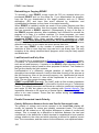
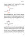
EZNEC User Manual
are calculated for you. You can position the loop anywhere, and can orient it
with its axis in any of the three principal directions.
Loop Resizing
You can use the loop resizing feature (Wires Window, Wires menu, Change
Loop Size) to change the size of any polygonal loop. The first step is to
specify the loop, by selecting the wires in the Wires Window or View Antenna
display. Or you can click the selection before you select wires, in which case
you'll have to choose a set of wires in numerical sequence. The selected
wires have to be connected in a loop, of course, and no wires can be
connected to the loop other than the wires comprising the loop. If you've
recently created a loop, its wires will be entered as an initial choice. The
buttons and text box at the bottom of the dialog box allow you to modify the
size with any of three different operations, on any of three loop size
measurements.
Radial Creation
EZNEC's automated radial creation feature is a convenient way to make a
group of radial wires. This feature is accessed from the Wires Window, Create
menu, Create Radials selection. When this selection is made, a dialog box
appears which prompts for a range of "prototype" wires. To make a simple set
of radials, you should first create a single radial wire. End 1 of the radial wire
should be where you want the center of the radials to be. Enter its number as
both the first and last wires in the prototype group. In the bottom box, enter
the total number of radials you want the finished structure to have, then click
Ok. The radials will be created, fanning out evenly around end 1 of the
prototype wire. A vertical wire can't be used as the prototype.
More complex radial structures can be made by specifying a group of wires as
the prototype radial to be copied. A prototype group of wires has to be
sequentially numbered (that is, you can't use wires 1, 2, and 4 as the
prototype group, for example) and must be connected end 1 to end 2. This
group of wires will then be duplicated, centered around end 1 of the first wire
in the prototype group. The first wire in the group can't be vertical, since this
would result in the first wire of the copies all occupying the same space.
Radial wire structures in orientations other than the horizontal plane can be
made by first creating the radials, then using the Rotate Wire feature to rotate
the structure to the desired orientation.
Wire Grid Creation
The automated wire grid creation feature is available only in EZNEC Pro
programs (EZNEC Pro/2 and EZNEC Pro/4). For information about manually
creating wire grid structures, see Wire Grid Modeling. This feature also allows
creating a closed wire grid box.
A wire grid is a good way to simulate a flat, solid, conductive surface such as
a metal roof or car top, or an enclosed box. A wire grid looks like a screen,
with each side of each screen hole made from a wire. (See the diagram in the
About Wires section.) In general, the best implementation is for each side of
each hole to be a single one-segment wire. Although wire grid modeling is an
art in itself, a few general rules have evolved which give good results for most
situations. One is that the size of the holes (that is, the wire spacing) shouldn't
60