1
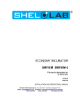
VACUUM OVEN
Model: VPX9-2
Installation and Operation Manual
Sheldon Manufacturing, Inc. P.O. Box 627, 300 N 26th Avenue, Cornelius, Oregon 97113
EMAIL: tech @ Shellab.com; www.Shellab.com
1-800-322-4897 (503) 640-3000 FAX (503) 640-1366
TABLE OF CONTENTS
SECTION 1.0
RECEIVING AND INSPECTION
SECTION 2.0
INSTALLATION
SECTION 3.0
PRECAUTIONS
SECTION 4.0
GRAPHIC SYMBOLS
SECTION 5.0
CONTROLS OVERVIEW
SECTION 6.0
OPERATION
SECTION 7.0
MAINTENANCE
SECTION 8.0
PARTS LIST
UNIT SPECIFICATIONS
WIRE DIAGRAM
REV. 04/04
4861421
This is a general-purpose vacuum oven for professional, industrial or educational use
where the preparation or testing of materials is done in a working environment that is at
approximately atmospheric pressure, and no flammable, volatile or combustible materials
are being heated. This oven is not intended for hazardous or household locations or use.
2
1
Section
RECEIVING AND INSPECTION
Your satisfaction and safety require a complete understanding of this unit. Read
the instructions thoroughly and be sure all operators are given adequate training
before attempting to put the unit in service. This equipment must be used only
for its intended application; ANY ALTERATIONS OR MODIFICATIONS WILL VOID
YOUR WARRANTY .
1.1
Inspection: The carrier, when accepting shipment, also accepts responsibility
for safe delivery and is liable for loss or damage. On delivery, inspect for visible
exterior damage, note and describe on the freight bill any damage found, and
enter your claim on the form supplied by the carrier.
1.2
Inspect for concealed loss or damage on the unit itself, both interior and exterior.
If necessary, the carrier will arrange for official inspection to substantiate your
claim.
1.3
Return Shipment: Save the shipping crate until you are sure all is well. If for
any reason you must return the unit, first contact your customer representative
for authorization. Supply nameplate data, including model number and serial
number. Please see the manual cover for information on where to contact
Customer service.
1.4
Accessories: Verify that all of the equipment indicated on the packing slip is
included with the unit. Carefully check all packaging before discarding. The oven
is equipped with three (3) shelves. No vacuum pump is supplied with this unit.
3
2
Section
INSTALLATION
Local city, county or other ordinances may govern the use of this equipment. If you
have any questions about local requirements, please contact the appropriate local
agency.
Installation of the 1495 requires hard wiring and is best performed by a qualified
electrical technician. A 20 amp circuit breaker may be used provided that all other
requirements in article 422 of the National Electric Code (USA) are met. Other areas
may require a different installation.
Under normal circumstances this unit is intended for use indoors, at room temperatures
between 5° and 40°C, at no greater than 80% Relative Humidity (at 25°C) and with a
supply voltage that does not vary by more than 10%. Customer service should be
contacted for operating conditions outside of these limits.
2.1
Power Source: The electrical supply circuit to the vacuum oven must conform to
all national and local electrical codes. Consult the oven’s data plate for the
voltage, cycle, and amperage requirements before making connection.
VOLTAGE SHOULD NOT VARY MORE THAN 10% FROM THE DATA PLATE
RATING. This unit is intended for 50/60 Hz operation. A separate circuit is
strongly recommended to prevent possible loss of product due to overloading or
failure of other equipment on the same circuit.
2.2
Location: When selecting a site for the oven, consider all conditions that may
affect performance, such as extreme heat from radiators, stoves, other ovens,
autoclaves, etc. Avoid direct sun, fast-moving air currents, heating/cooling ducts,
and high traffic areas. To ensure proper air circulation around the unit, allow a
minimum of 5cm between the oven and any walls or partitions that might obstruct
free airflow.
Please note that once a location is chosen and the unit has been completely
installed, the castors at the base of the cart should be locked into place to
provide optimum working and safety conditions.
2.3
Lifting / Handling: This unit is heavy and care should be taken to use
appropriate lifting devices sufficiently rated for this load. Please see section 8,
Unit Specifications for weight information. Units should only be lifted from their
bottom surfaces. Doors, handles and knobs are not adequate for lifting or
stabilization. The unit must be completely restrained from tipping during lifting or
4
transport. All moving parts, such as shelves and trays should be removed and
doors need to be positively locked in the closed position during transfer to
prevent shifting and damage.
2.4
Cleaning: The oven interior was cleaned at the factory, but not sterilized.
Remove shelves and shelf slides, if installed, and clean with a disinfectant that is
appropriate for your application. Refer to section 7.1 for complete cleaning
instructions.
WARNING: Never clean the unit with alcohol or flammable cleaners with the unit
connected to the electrical supply. Always disconnect the unit from the electrical
service when cleaning and assure all volatile or flammable cleaners are evaporated
and dry before reattaching the unit to the power supply.
2.5
Shelf Placement: Place shelves in the chamber at the desired location.
5
3
Section
PRECAUTIONS
NOTE: THIS IS NOT AN EXPOLOSION PROOF OVEN.
3.1
Do not place or use explosive, combustible, or flammable materials in the oven.
3.2
Do not use sealed containers in the oven chamber.
3.3
Disconnect the unit from electrical power source before attempting to make any
repairs or component replacements.
3.4
If a mercury thermometer is used and breakage should occur, all spilled mercury
must be completely removed from the chamber.
3.5
This oven IS NOT suitable for use in Class I, II, or III locations as defined by
the National Electrical Code NFPA 70, U.S.A.
6
4
Section
GRAPHIC SYMBOLS
Your oven is provided with a display of graphic symbols to help in identifying the use
and function of the available adjustable components.
2.1
This symbol indicates that you should consult your manual
for further description of a control or user item.
2.2
Indicates “AC Power”.
2.3
Indicates “Temperature”
2.4
Indicates “Over Temperature Protection”
2.5
Indicates “Vacuum”
2.6
Indicates “Earth Ground”
2.7
Indicates “Potential Shock Hazard”
7
5
Section
CONTROLS OVERVIEW
Figure 1
Main
power
switch
Vacuum
pump switch
High limit
control
Reset
button
Watlow 981 temperature
controller
Vent valve
Vacuum valve
Vacuum gage
5.1
Main Power Switch: The Main power I/O (on/off) switch is marked POWER
and controls all power to the unit. It must be in the I, or ON position before
any systems are operational including the vacuum pump. The green pilot light
in the switch will be on when the unit is energized.
5.2
Vacuum Switch: This I/O (on/off) switch is marked VACUUM and it controls
power to the vacuum pump. The green pilot light in the switch will be on when
the pump is energized. See section 6.1 for further discussion on connecting
the vacuum pump.
5.3
Main Temperature Control:
This is a microprocessor based
temperature/time control with ramp and soak capabilities. The Watlow 981
controller has digital displays and front panel controls for inputting set point
temperature, calibration and program configurations. Detailed instructions are
in the Watlow 982 Users Manual included with your instruction packet.
8
5.4
High Limit Control: This control is completely independent of the Main
Temperature control and provides safety temperature protection for the
oven. If for any reason the oven temperature rises above the Main
Temperature control’s set point, a properly adjusted High Limit control will
limit the rise to approximately 10°C above the Main Temperature set point.
In addition to this safety feature, there is a power relay that works in
conjunction with the High Limit. The power relay is deactivated if the High
Limit set point is reached, and incoming power to the heating elements
and temperature controller will be cut off.
The High Limit Control is equipped with an adjustment knob that requires
a flat-edged tool when making adjustments. This is to reduce the chances
of accidental changes.
5.5
Reset Button: This button is located just below the High Limit Control.
During initial start-up, power interruptions or after activation of the High
Limit Control, this button must be depressed to reset the main power
relay.
5.6
Vacuum Gauge: This is a digital gauge that shows the chamber vacuum
level in measurements of Torr and m/Torr. The gauge Display is ON
when the Main Power switch is activated. Please note: although this
gauge has the capacity to act as a controller as described in the enclosed
Terranova Vacuum Control manual, it has not been wired for these
capabilities. In this application, it functions only as a gauge with a display.
5.7
Vacuum Valve: This valve is located just below the control panel in a
recessed box and marked VACUUM. It controls the vacuum of the
chamber when opened counterclockwise and the pump is operating.
5.8
Vent Valve: This valve is adjacent to the Vacuum valve and releases
vacuum in the chamber, returning it to atmospheric pressure when the
knob is turned counterclockwise. This valve must be closed (clockwise)
when evacuating the chamber.
5.9
Fuses: These protective devices are located on the oven’s outside rear panel,
next to the power input connections. They protect the oven against accidental
overload of the vacuum pump outlet. This outlet is located in the vacuum pump
area on the bottom of the control panel box. If the fuse(s) are blown, remove any
plugs from the vacuum pump outlet, locate the fault and replace the fuse(s) with
the same type and rating. Rating information is located on a label next to the
fuses.
9
6
Section
OPERATION
This unit is not supplied with a vacuum pump; however, plumbing and
KF25 connections are provided, as well as mounting studs at the base of
the cabinet. This unit requires a 220 volt pump to connect to the main
power supply from the unit. If you have a pump that you intend to use for
this application, all maintenance and instructional information should be
obtained by the pump manufacturer and adhered to. In the Parts List
located at the back of this manual, a pump assembly is listed as an
available accessory. This assembly is listed as a convenience but does not
imply that it is the required pump for the unit, as individual operating
requirements may vary.
6.1
Power Supply: The oven power requirements are listed on the data plate.
THE POWER SUPPLY SHOULD NOT VARY MORE THAN ± 10% from
this rating. There is a convenience outlet located inside the cabinet at the
top, which is rated 220v, 15amp. This outlet is for connecting the power
cord of the pump to the unit, allowing the pump to be activated when the
VACUUM switch is turned ON.
6.2
It is important to use vacuum tubing for all the vacuum hookups. Other
types of tubing may collapse and prevent complete evacuation. All
plumbing connections to the pump must be solid and tight to eliminate
possible leakage.
6.3
When placing objects or samples within the chamber be mindful of the
sensing probes mounted on the back wall. Any pressure against them
can cause breakage and replacement will be necessary.
6.4
The door should be closed and latched by swinging the latching arm into
place and turning the knob clockwise until it grabs and the door is snug
against the body.
6.5
Power: Turn the POWER switch to the ON position. This controls all
power to the unit including the convenience outlet and VACUUM switch.
Turn the High Limit Control to its maximum position - clockwise - in order
that it not interrupt the setting of the Main Temperature controller and
deactivate the power relay.
10
6.6
Reset button: As noted in section 5.5, the RESET button must be pushed
to reset the power relay in order that power be available to the unit.
6.7
Apply Vacuum to the Chamber: Close the VENT valve by turning it fully
clockwise (right.) Turn the VACUUM switch ON (I) and open the
VACUUM valve by turning it fully counterclockwise (left). Watch the
vacuum gauge display, and when the desired vacuum is achieved, close
the VACUUM valve completely clockwise. Then turn the VACUUM switch
OFF. Some applications may require that the vacuum pump stay on.
Note that ultimate vacuum levels may take some time. This is especially
true if the contents in the chamber have oil or moisture in them.
6.8
Set Main Temperature Control: To enter the desired set point
temperature press either the Up or Down arrow pad until the desired
temperature appears in the lower digital display window of the controller.
Note: the controller is configured in °C. The upper digital window displays
the process temperature (the temperature inside the oven.) Five to ten
seconds after you change the temperature set point the controller will
initiate the change. If heat is called for, the LED next to L1 will light. This
is the main heater circuit. When this light is on, the oven is calling for heat.
The Watlow 981 programmable controller is capable of storing and running
up to 24 steps of ramp and soak temperature profiles. Refer to the Watlow
982 User’s Manual for complete instructions on operating and
programming this controller.
NOTE: Slight vapor or smoke may occur in the initial heat-up. This is
a normal occurrence when the oven is first brought up to
temperature and protective coatings on the elements become hot.
6.9
Setting High Limit Controller: As stated in section 6.5, the High Limit
should be set to its maximum position to allow the Main control to be set
without interruption. Once the Main Temperature control is stable at the
desired set point, the High Limit needs to be adjusted. To do this, turn the
control knob counterclockwise until the oven trips off. Next, turn the knob
clockwise one or two increments on the scale (the scale is in reference to
the current setting only.) Push the RESET button to reactivate the power.
Now the High Limit Control is set at approximately 10°C above the Main
Control. If the Oven does not turn on, the High Limit is not set higher than
the Main Temperature set point and needs to be adjusted clockwise
another increment.
11
7
Section
MAINTENANCE
NOTE: Prior to any maintenance or service on this unit, disconnect the
service cord from the power supply.
7.1
Cleaning: Cleaning the oven on a regular basis improves vacuum
performance. To prepare the oven for cleaning, remove the shelves, shelf
slides and door gasket. All of these components are autoclavable, or clean
as described below. Be careful not to disturb the sensors located on the
back wall; any undue pressure may cause breakage and replacement will
be necessary. Disinfect with a solution that is suitable for your application.
Any oily residue or moisture in the chamber should be removed after each
operation to ensure maximum performance.
Using a lint free rag, wash the oven chamber and all parts with isopropyl or
ethyl alcohol and dry thoroughly. DO NOT use chlorine based bleaches or
abrasives as this may damage stainless steel surfaces. DO NOT use spray
cleaners that might leak through openings and cracks and get on electrical
parts or that may contain solvents that will harm the coatings.
When cleaning the gasket, handle it carefully so as not to impair the
positive seal.
WARNING: Always disconnect the unit from the electrical service when
cleaning and assure all volatile or flammable cleaners are evaporated and
dry before reattaching the unit to the power supply.
7.2
Vacuum pump maintenance: Refer to the operation manual supplied with
your vacuum pump for detailed descriptions of recommended maintenance
routines. Oil levels, replacement of sorbent charge, and exhaust filter are
typical areas for attention. Contact your vacuum pump supplier if you do
not have an operation manual.
12
8
Section
PARTS LIST
Description
220V
Circuit Breaker, 20A
Controller
Element, Long (x2)
Element, Med (x4)
Element, Short (x2)
Gasket 12 x 12 (Viton)
Gasket 24.5 x 26 (Viton)
Glass
High Limit Control
I/O Switch, green
KF25 blank
KF25 centering ring
KF25 hinged clamp
KF40 blank
KF40 centering ring
KF40 hinged clamp
Pump assembly, option
Solid state relay
Switch, Reset
Vacuum gauge
Vacuum Gauge Tube
13
1100500
1750587
9570876
9570877
9570878
3450560
3450559
110107
1750571
103351
3100595
3100592
3100595
3100607
3100609
3100608
9990614
102162
101746
8550501
8550502
UNIT SPECIFICATIONS
Weight
Dimensions
Shipping
Net
770 lbs.
492 lbs.
Exterior WxDxH
Interior WxDxH
36 x 44 x 62”
28 x 24 x 24”
Cubic Feet
Capacity
9.33
Range
Uniformity
Rise Time
Temperature
Ambient + 10° to
200°C
+10°C @ 200°C
60 min. to 100°C
Volts/Hz
Amps
230v 50/60 hz
15A
Electrical
14
WIRING DIAGRAM
15