1
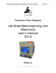
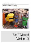
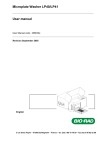
Syringe Pump series user’s mannual Fnm Co. Fanavaran Nano-Meghyas Syringe Pump series user’s mannual 2013 Fnm.ir 1 Syringe Pump series user’s mannual Fnm Co. General Information: ................................................................................... 3 Calibration.............................................................................................. 3 Warranty ............................................................................................... 3 Repair Facilities and Parts ....................................................................... 3 CAUTION ................................................................................................ 3 Maintenance and General Safety Summary ................................................... 4 GENERAL SAFETY SUMMARY .................................................................. 4 To Prevent Hazard or Injury: ..................................................................... 4 Warning: ................................................................................................ 5 Introduction .............................................................................................. 5 Theory of Operation ................................................................................. 5 Features ................................................................................................ 6 Package contents: .................................................................................. 8 Applications............................................................................................ 8 Nomenclature of different models of syringe pumps.................................... 8 Specifications of different models of syringe pumps .................................... 9 Installation ............................................................................................. 9 Physical installation .............................................................................. 9 Installation steps: ................................................................................ 9 Software installation: ............................................................................ 10 Driver installation:.............................................................................. 10 Loading the Syringe .............................................................................. 11 User Interface ...................................................................................... 12 DESCRIPTION OF KEYS.......................................................................... 12 Data Entry Keys ................................................................................ 13 Set Keys ........................................................................................... 13 Operational Keys ................................................................................ 19 Software interface ................................................................................ 19 Toolbar .............................................................................................. 20 Controlling the direction of movement and fast relocation: ..................... 20 Graph specifications: .......................................................................... 21 Rate-Time Curve: ............................................................................... 22 The curve equations: .......................................................................... 22 Setting the specifications to inject a solution: ...................................... 23 Example 1 ...................................................................................... 23 Example 2 ...................................................................................... 24 Appendix A: Equations ........................................................................ 25 Appendix B: Syringe inside Diameter .................................................... 25 Appendix A: Syringe neddle conversion chart......................................... 25 2 Syringe Pump series user’s mannual Fnm Co. General Information: Serial Number All inquiries concerning our product should refer to the serial number of the unit. Serial numbers are located on the rear of the case. Calibration All syringe pumps are designed and manufactured to meet their performance specifications at all rated voltages and frequencies. It’s necessary to calibrate the instrument every 6 month. It’s suggested that choose a 10-mililitre syringe and a 1-mililitre target, then measure the amount of pedal (pusher block) movement forwards in 1, 6, 60 and 120 ml/h. The movement must be 12.73 mm. To measure the accuracy of internal timer, the injection time must be 60, 10, 1 and 0.5 minutes. Warranty FNM syringe pump is warranted for a period of one year (for replacing the parts) and 5 years (for repairing) from date of purchasing. At its option, Fnm Co. will repair or replace the unit if it is found to be defective as to workmanship or material. This warranty does not extend to: Damage resulting from transportation, wrong connections with other systems, connection with defective equipments, power fluctuations, fire or intensive heat, water or corrosive chemicals, dust, lightning, natural disasters, collision, misusing the instrument or neglecting the manual description. The instruments that have been repaired by other companies. The instruments that have been manipulated. Damaging the instrument labels or holograms Damage resulting from installation or updating the files, software, program and firmware by irresponsible people. Services extend to ten years in return for the payment of costs. Repair Facilities and Parts Fnm Co. stocks replacement and repair parts. While ordering, please describe parts as completely as possible. Preferably by using the part numbers, a sample or drawing. CAUTION This pump is not registered with the FDA and is not for clinical use on human or veterinary patients. It is intended for research use only. 3 Syringe Pump series user’s mannual Fnm Co. Maintenance and General Safety Summary GENERAL SAFETY SUMMARY Please read the following safety precautions to ensure proper use of your syringe pump. To avoid potential hazards and product damage, use this product only as instructed in this manual. If the equipment is used in a manner not specified by the manufacturer, the protection provided by the equipment may be impaired. To Prevent Hazard or Injury: Use Proper Line Cord Use only the specified line cord for this product and make sure line cord is certified for country of use. Use Proper Power Supply The pump is supplied with an approved power supply and line cord. To maintain the safety integrity of the device, use only one of the following power supplies: Plastic body pumps: 12 Volt DC 3A Metal body pumps: 100 – 240 V AC, 50-60 Hz Ground the Product This product is grounded through the grounding conductor of the power cord. To avoid electric shock, the grounding conductor must be connected to earth ground. Before making any connections to the input or output terminals of the product, ensure that the product is properly grounded. Make Proper Connections Make sure all connections are made properly and securely. Use Proper Fuse Use only specified fuses with product. Avoid Exposed Circuitry Do not touch any electronic circuitry inside of the product. Do Not Operate with Suspected Failures If damage is suspected on or to the device, do not operate it. Contact with qualified service personnel. Place the device in Proper Environment Review the operating manual for guidelines for proper operating environments. Keep the instrument in a dry, clean and flat place. Avoid connecting the ventilation fan near the walls. 4 Syringe Pump series user’s mannual Fnm Co. High viscosity solutions Don’t use high viscosity solutions and syringes with very low diameter nozzle (High gauges size). Finishing the solution Switch off the system after finishing the solution (Note: the target must always set at a suitable value). Clean the syringe pump Clean the keyboard and body of the instrument with a medium detergent. Oiling Oil the screws and their connections in certain time. Nozzle Cleaning After finishing the work, clean inside of nozzle and connections completely, put a piece of thin wire inside the nozzle in order to avoid drying polymeric solution. Observe all Warning Labels on Product Read all labels on product to ensure proper usage. Using an organic solvent Notice that the used hose is able to solve in some organic solvents, so use Teflon or Polyethylene hose instead of PVC. Please inform FNM Co. staff if there is any problem. The instrument limits: Accuracy largely depends on the syringe and its diameter. Measurement error will directly cause the injection error. Warning: The sound alarm inside the device can be set up to warn the user when completing each order. Introduction Theory of Operation Syringe pump The syringe pump of Fanavaran Nano-Meghyas co. has been designed as a low cost product in order to use of a variety of syringes. The system is able to inject the certain volume of solution with different rates. All six models in the SP1000 and SP2000 series employ a microcontroller which controls a small step angle stepping motor that drives a lead screw and Pusher Block. Micro-stepping techniques are employed to further reduce the step angle, eliminating flow pulsation. A keypad is used for entering the data to the pump. Data can also be 5 Syringe Pump series user’s mannual Fnm Co. entered via an USB connector located on the rear panel in S models. The diameter of the syringes is entered via the keypad and the internal microprocessor drives a precision stepper motor to produce accurate fluid flow. The pump can hold syringes of any make from about 1 μl to 60ml for the dual syringe version and from 1 μl to 50ml for the ten-syringe version. The diameter of the syringes is entered via the keypad and the internal microprocessor drives a precision stepper motor to produce accurate fluid flow. Nonvolatile memory stores the last syringe diameter and flow rate along with other configuration data. The SP1000/SP2000 Programmable and software models are equipped with all the functions of the ordinary models along with additional features to provide the Withdraw (Refuse) function and along with additional features to provide Programmable functions. The P and S model’s additional features include five additional function keys on the keypad, Mode, Program, Refill and two pedal position control keys. Usage of the keys is described in detail in this manual. Front and rear of syringe pump Features Bright Display and Easy-To-Use Interface Using a 2- or 4- row display causes to show the essential information, and its background light facilitates the reading of information in the darkness. Using 20-25 keys avoids the need for a multi-menu, so the system will be set and will start to operate by pressing a few keys. Different parameters such as flow rate, syringe diameter, maximum of injection are adjustable. Pressure and rate SP1000 can deliver solution up to 1000 ml/hour with a single 60 ml syringe. Maximum pressure is dependent on syringe size. 6 Syringe Pump series user’s mannual Fnm Co. Syringe Table and Custom Syringes If a non-standard syringe is to be used, enter the inside diameter of the syringe in millimeters. If a standard syringe is to be used, use the pump’s built-in syringe table. Syringes are arranged according to manufacturer and material, and then according to size. (See Appendix A). Infusion and Refill Rates Specify independent rates for infusing and refilling. This allows a slow infusion rate then a fast refill. Target Volume Specify the volume that is to be infused or refilled. The pump will run at the rate specified until this volume has been delivered in the Volume mode. Modes of Operation Pump Runs continuously, in the infuse or refill directions, until stopped. Refill not applicable to the Infusion model. Volume Runs until a specified volume has been pumped or refilled. Refill not applicable to the Infusion model. Program The pump operates according to a specified sequence of instructions. Nonvolatile Memory All operational data entered into the pump from the keypad or from a computer will be stored, including the program. Visual/Audible Alarm The alarm can be selected to be a silent or an audible signal in addition to display alarms in Alarm menu. Program Storage (Programmable and software models) Programmable model can store up to 9 program sequences. Smooth injection: Using a high accuracy motor and driver profiles deliver very smooth and consistent flow, that is virtually pulse free. 7 Syringe Pump series user’s mannual Fnm Co. Adjusting the Pusher Block: Using four keys that move the location of pusher block forward or backward can cause adjusting of its position rapidly. Package contents: Contents of the syringe pump package are Power cable, User manual and Fuse. In software models, software CD and USB cable is also included. Applications The system is used for small controlled injection of solution. Some applications are: Cellular injection Controlled injection of drug Electrospinning (caution: the earth connection must be completed to avoid the influence of high voltage power supply) Controlled injection of a reactant into the reactor Lab-on-a-chip Nomenclature of different models of syringe pumps Example: SP1000HPM; maximum 2 syringes, High Precision, Programmable, Metal body 8 Syringe Pump series user’s mannual Fnm Co. Specifications of different models of syringe pumps Installation: Physical installation The following conditions must be noticed at the place where you work. A dry, clean and hard surface for keeping the instrument. Minimum of one inch (about 2 cm) clearance around the pump suitable bio-environmental conditions a proper ventilation Installation steps: Plug in the power cable (in metal models) or a 12-volt adaptor (in plastic models), and then connect it to the input voltage of pump. Turn on main power switch located on the rear panel. The display will now illuminate indicating that the power connections are correct. The display will indicate FNM Co. internet address for 3 seconds. In this step the device is ready to use. 9 Syringe Pump series user’s mannual Fnm Co. Software installation: There is a computer software program only in HSM models with a CD. when the CD is put into CD-ROM drive, the installation program will run automatically. The steps are: 1. Click on “ software installation” button 2. Click on “ Next” button 3. Select the installation path, then click on “ Next” 4. Click on “ Next” 5. The installation will be started 6. Click on “ close” button Driver installation: a) Connect the USB cable to the computer and setup b) Switch on the computer and setup c) Click on the “Drive Installation” button then, installation will be started. 10 Syringe Pump series user’s mannual 1. 2. 3. 4. 5. 6. Fnm Co. Back Block Guide Screw Pusher Blocks Retaining Bracket (Pusher Block) Syringe Clamps 7. Syringe Clamp 8. Syringe 9. Syringe Holder Block 10. Retaining Bracket (Syringe Block) 11. Allen Screw 12. Bearing Loading the Syringe 1. 2. 3. 4. 5. 6. Adjust the syringe pusher block (4) by pressing the positional switches on the keypad. Raise the spring loaded syringe retainer (7) and swing it out of the way. Lay the loaded syringe in the ‘V’ shaped syringe block (9). Swing the syringe retainer (7) so it holds the syringe in place. Move the pusher, so it makes contact with the syringe plunger. Adjust pusher block thumbscrews & bracket (5) & (10) until the syringe plunger is completely captured. 7. Tighten down thumbscrews on syringe block bracket so that it captures flanges on syringe barrel. 8. Tighten thumbscrew into place when switch is set. 11 Syringe Pump series user’s mannual Fnm Co. User Interface Fnm syringe pumps have 2 types of panels. These panels have 20-25 keys and a 2- or 4row display. Programmable and software models Keypad (left). Ordinary model Keypad (Right) The user interface consists of a keypad with a display area. The panel consists of a 4-row, 20-character alphanumeric vacuum green or blue fluorescent display. The display will show one of three types of messages: Default display, setting display, or an informational message. The first row is divided into three sections: flow rate with 3 decimal points, injection unit and “>>” or “||” part that shows the moving state of the motor. The second row is injection volume with the unit expressed as ‘ml’ for milliliters; “ul” for microliter and “nl” for nanoliter. The third row is target volume. Setting displays are used to facilitate entering data into the pump. Data entry will be discussed in detail later in this section. Informational messages occur at various times to indicate such items as a data setting out of range, or a detected problem such as the pump out of range flow rate. Pressing any key clears the message from the display. DESCRIPTION OF KEYS The keypad consists of 20 keys on the ordinary model and 25 keys on the Programmable and software models. The keys are used for entering control information and data into the pump. These keys are grouped into 3 sections: Set keys, operational keys, and Data Entry keys. 12 Syringe Pump series user’s mannual Fnm Co. Data Entry Keys Used to enter numeric data values or access special features. ENTER: Saves and stores displayed data value in memory when setting a data item. Cancel: Cancel the new displayed data and return the stored value. Set Keys Three parameters are adjustable: Target (The Maximum of injection volume) If you want to stop the system after injecting a certain volume of solution, you must press the button “Target” Then enter the volume by numeric keys on the panel (). After injection, the system will be stopped and the following page wills appeare. For removing the last entered number, you can use the “<=” key. In order to save the value, press just “Enter” switch. If you want to have the previous value, press just “Cancel” key. Nonstop injection: It must be to set Target in 0 to have a nonstop injection. Diameter (The diameter of used syringe): It’s the most important parameter in calculating the flow rate, so it’s necessary to measure and enter it correctly. First, press the button “Diameter”, then enter the diameter value on the page (that has been appeared) by pressing the numbers on the panel. When the syringe is changed, the new diameter value must be set. Units are in millimeters (mm). Enter the inside diameter (ID) of the syringe you wish to use. If you do not know your syringe diameter, refer to appendix B for nominal inside diameters of most popular syringes. For the greatest accuracy or if your syringe is not listed in appendix B, measure the inside diameter with a vernier caliper or other precision measuring tool. Record this value for future use. 13 Syringe Pump series user’s mannual Fnm Co. Flow rate (Infuse rate): The unit of flow/infuse rate is milliliter/hour, microlitre/min and nanoliter/second that is volume of the solution that is injected from the syringes per hour, minute and second. For setting the rate, press the “Rate” key, the following page appears. Finally, enter the rate value. Press the “Enter” key while setting. The display shows current programmed rate while running in program mode. The Max. and Min of rate: The Maximum and Minimum of rate depend on the syringe diameter. In order to increase injection accuracy, it’s better to use a 5-ml syringe for rates less than 10 ml/h, and a 2-ml syringe for rates less than 2 ml/h. For more rates, syringes larger than 5 ml must be used. The information about choosing proper rates is at the end of the manual description. If the chosen rate is more than the definite rate, the display will show “Error”. In this case, you must use a larger syringe. Changing the injection unit in HOM models: In order to change the unit in SP1000HOM, press the ”Rate” switch twice. The unit will be microlitre/min. 14 Syringe Pump series user’s mannual Fnm Co. Reset the injected volume: The “Cancel” key must be pressed twice to set the injected volume in zero. . Finishing the solution: In some models, when the pedal (Pusher Block) reaches to the end position, the system will automatically stop in order to avoid damaging to screws and the motor, so the pedal must be moved backwards by the positional keys and the syringe have to be changed. Note: The most of models don’t have this switch, so be careful of finishing the solution. The last data is saved in the memory of system. If the unit of volume is changed, the previous data will be removed and “zero” will be replaced. For example, if the last volume is 2000 microliter and the unit is changed to “ml”, it will be remove (because 2000 ml is very large) and “zero” will be shown on display. Mode/Menu: There is a menu in HPM and HSM models that is available by pressing the “Mode” key. 1. Autofill: In some cases, it’s necessary to return the syringe to its first position because of refilling it. At first, enter “Autofill”, then select from 1 to 99 and press “Enter”. The chosen number is times of repetition. 15 Syringe Pump series user’s mannual Fnm Co. Finally, press “Autofill” on the menu. The “AF” will be appeared on the right of 2nd row. 2. Infuse/Refuse (Pumping Direction): “Infuse” section on the menu is used for changing the motor direction. If the key is chosen, the pusher block will move forwards, and by choosing the key , the pusher block will move backwards. 3. Programming: In the Program Mode the pump can make complex dispenses including changes in rate and target volume. These complex dispenses are easily programmed from the keypad. Program Description A program is made up of a set of sequences. Each sequence is a set of operating instructions for the pump to follow. When the pump starts in the PROGRAM mode, the pump will start at sequence 1 and execute the operating instructions in that sequence. When the pump has completed the instructions for a sequence, it will go to the next sequence and execute the instructions in that sequence. The pump continues this process until the pump is manually or remotely stopped, or the last sequence has been completed. As shown on Programming page above, the first row is the Sequence No. that is chosen by pressing the key. The 2nd row (Prog Mode) shows two states of injection: Time and volume mode that are chosen by pressing the key. One of two strategies may be chosen for a sequence’s target. Strategy 1 (Target Volume) pumps until a target volume is reached, while 16 Syringe Pump series user’s mannual Fnm Co. Strategy 2 (Time Interval) pumps until a target time interval has elapsed. In this mode enter the time unit in hour, minute and second. Programming in Time mode: The unit of time can be changed by pressing the key. Press the “Enter” key to begin entering a program. When the required operation is displayed, press the “Enter” key. Extra information may be requested. According to the chosen Sequence No. And Time unit, the proper time and rate of injection are selected. After selecting each value, the “Enter” key must be pressed. In order to exit each step, the “cancel” key must be pressed. Programming in Volume mode: Dispense specified volume. Runs at selected flow rate until a volume is pumped, then pump will stop. The maximum volume and proper rate of injection are selected. After selecting each value, the “Enter” key must be pressed. In order to exit each step, you must press the “cancel” key. By pressing the “Program” key on the main menu, the “P” will be appeared on the right of the 2 row that is the state of motor in “Pragram”. nd 17 Syringe Pump series user’s mannual Fnm Co. 4. Alarms: There are four types of alarms in the system: Key Name End Task Description Refill Alarm while refilling the syringe Target Alarm after injecting the target volume of solution Limit Sw Alarm when end switch is pressed Alarm after completing every task By pressing the keys 1-4, the alarm state will be changhed from On to Off or Off to On. 5. Fast Forward & Fast Reverse (Pusher Block adjustment) The pedal can be shifted by pressing the used for having a certain shift. and keys. The FF & FR menu is Note: when a certain pedal shift is performed, it won’t be able to stop, so be careful, if a wrong shift is occurred, the pedal will hit the back or front of the instrument that can cause a mechanical damage. 6. Units: A unit menu is used for defining the unit of injection rate and volume. key Flow Rate Unit ml/h Flow Volume Unit Mililiter key Flow Rate Unit nl/sec Flow Volume Unit Nanoliter ul/min Microliter mm/min Milimeter ml/min Mililiter mm/hour Milimeter Note 1: If the syringe diameter is less than 4 mm, you can choose the key 4. 18 Syringe Pump series user’s mannual Fnm Co. Note 2: If you choose the keys 5 or 6, the injection rate and volume will NOT depend on the syringe diameter. Operational Keys RUN/STOP (Starting the flow) In order to start, press “Run” key. By pressing this key, the injection will start and by repressing it, the injection will stop. Note: There is only one switch located in the middle of this key. Enter/Cancel In order to save the value, press “Enter” key. If you want to have the previous value, press “Cancel” key. Note: There are two switches located under “Enter” and “Cancel” keys. Pusher Block adjustment Use these switches for adjusting the position of pedal (pusher block) Software interface: The software interface in the syringe pump is shown in the following image: 19 Syringe Pump series user’s mannual Fnm Co. Menu Tool Box adjust the position of pedal (pusher block) and direction of movement Displaying the current information Setting the parameters to draw a Rate-Time curve Setting the curve equations and their time range Rate-Time curve display and the related keys Device state and computer connection display Toolbar: Removing the information and creating a new document with empty fields Opening the previous saved document Saving the data Saving the data with a new name Printing the data Exhibiting the printed page Help Controlling the direction of movement and fast relocation: 20 Syringe Pump series user’s mannual Fnm Co. Determining the movement direction of the syringe Fast relocation of the pusher block to backwards Fast relocation of the pusher block to forwards Current Data: Injected volume of solution Unit of injected volume milliliter and micro-liter Reset the injected volume to zero Exhibiting the current rate of injection Determining the unit of injection rate: ml/h and µl/min The rest of time to complete the injection Graph specifications: Determining the type of graph Rate: drawing the rate-time curve until specific time Volume: drawing the rate-time until specific volume Number of repetition of the curve Determining the syringe diameter (mm) Determining the unit of flow rate 21 Syringe Pump series user’s mannual Fnm Co. Rate-Time Curve: Drawing the graph by using the equations Restarting/Pausing the injection Starting/Stopping the injection Rate-Time Curve The curve equations: If chosen graph is ‘Rate’, the curve equation and its time range will be needed. And if chosen graph is ‘Volume’, the curve equation and its injection volume range will be needed. 22 Syringe Pump series user’s mannual Fnm Co. Determining the curve equation Determining time range of the curve Removing the current equation Adding another equation after the last one Determining the curve equation Determining the maximum volume of injected solution Determining the unit of maximum injected volume: 1) ml and 2) µl Removing the current equation Adding another equation after the last one Setting the specifications to inject a solution: 1. Setting the graph specifications (type of graph, sequence number of curves, syringe diameter and unit of flow rate). 2. Determining curve equations and their time/volume range 3. Drawing graphs by using the key 4. Operating the injection by using the key Example 1: Imagine that an injection must be done by a 10-mm-diameter syringe, according to the following equation: (Unit of flow rate is microliter/min) t 2 1.5 t 0 t 10 10 sin(t ) 20 10 t 50 20 50 t 70 At first, in the graph specifications section, we choose syringe diameter=10 mm, type of graph: Rate, and unit of flow rate: ul/min. The rate equation is: Rate = 1.5*t+t^2 , t(time)=10 s, then we press the key. In this step, we choose the 2nd equation as Rate = sin[t]*10+20, 23 Syringe Pump series user’s mannual Fnm Co. t=40s, and repress the key. Then, we choose the 3rd equation as: Rate = 20, and t=20s. The final result is shown in figure. Example 2: Imagine that an injection must be done three times by a 20-mm-diameter syringe, according to the following equation: (Unit of flow rate is microliter/hour). 10 t 2 cos(t ) 2000 Max V olume 0.1ml Max V olume 0.2ml At first, in the graph specifications section, we choose syringe diameter=20 mm, type of graph: Rate, unit of flow rate: ul/min. and sequence No. =3. The rate equation is: Rate = key. In this step, we abs[(10*t^2)*cos[t]] and the max of volume=0.1 ml. Then, we press the choose the 2nd equation as: Rate=2000 and the max of volume=0.2 ml. The final result is shown in below image. 24 Syringe Pump series user’s mannual Fnm Co. Appendix A: Equations Use “t” as variant. Name Description Example + Computes the sum of its two operands. 1.2 + 3.1 == 4.3 - Computes the subtract of the second operand from the first. 57.3 – 26.8 == 30.5 * Computes the product of its two operands. 4.5 * 3.0 == 13.5 / Computes the divide of the second operand from the first. 60 / 0.3 == 200 ^ Computes the first operand rose to the second operand. 2 ^ 10 == 1024 % Computes the remainder after dividing its first operand by its second. 11 % 3 == 2 25 Syringe Pump series user’s mannual Fnm Co. Name Description Example abs Returns the absolute value of a specified number. abs[-1] == 1 acos Returns the angle whose cosine is the specified number. acos[1] == 0 asin Returns the angle whose sine is the specified number. asin[1] == 1.5708 atan Returns the angle whose tangent is the specified number. atan[1] == 0.7854 atan2 Returns the angle whose tangent is the quotient of two specified numbers. atan2[-1, -1] == 3.9270 avg Return the average of input numbers. avg[1, 11, -2.5, -7.5, 8] == 2 ceiling Returns the smallest integer greater than or equal to the specified number. ceiling[-1.2] == -1 cos Returns the cosine of the specified angle. cos[3.1415] == -1 cosh Returns the hyperbolic cosine of the specified angle. cosh[2] == 3.7622 exp Returns e raised to the specified power. exp[1] == e floor Returns the largest integer less than or equal to the specified number. floor[-1.2] == -2 ln Returns the natural logarithm of a specified number. ln[2] == 0.6931 log10 Returns the base 10 logarithm of a specified number. log10[100] == 2 max Returns the larger of input numbers. max[1, -7.5, 8] == 8 mid Returns the middle of input numbers. mid[1, 11, -2.5, -7.5, 8] == 1 min Returns the smaller of numbers. min[1, 11, -2.5, -7.5] == -7.5 round Rounds a value to the nearest integer or specified number of decimal places. round[3.6] == 4 sign Returns a value indicating the sign of a number. sign[-5] == -1 sin Returns the sine of the specified angle. sin[3.1415] == 0 sinh Returns the hyperbolic sine of the specified angle. sinh[2] == 3.6269 sqrt Returns the square root of a specified number. sqrt[25] == 5 tan Returns the tangent of the specified angle. tan[0.7854] == 1 tanh Returns the hyperbolic tangent of the specified angle. tanh[2] == 0.9640 26 Syringe Pump series user’s mannual Fnm Co. Appendix B: Syringe inside Diameter 27 Syringe Pump series user’s mannual Fnm Co. Appendix C: Syringe Needle Conversion Chart Needle Nominal Outer Diameter Nominal Inner Diameter Nominal Wall Thickness Gauge inches mm tol. inches (mm) inches mm tol. inches (mm) inches mm tol. inches (mm) 7 0.180 4.572 ±0.001 (±0.025) 0.150 3.810 ±0.003 (±0.076) 0.015 0.381 ±0.001 (±0.025) 8 0.165 4.191 " 0.135 3.429 " " " " 9 0.148 3.759 " 0.118 2.997 " " " " 10 0.134 3.404 " 0.106 2.692 " 0.014 0.356 " 11 0.120 3.048 " 0.094 2.388 " 0.013 0.330 " 12 0.109 2.769 " 0.085 2.159 " 0.012 0.305 " 13 0.095 2.413 " 0.071 1.803 " " " " 14 0.083 2.108 " 0.063 1.600 " 0.01 0.254 " 15 0.072 1.829 ±0.0005 (±0.013) 0.054 1.372 ±0.0015 (±0.038) 0.009 0.229 ±0.0005 (±0.013) 16 0.065 1.651 " 0.047 1.194 " " " " 17 0.058 1.473 " 0.042 1.067 " 0.008 0.203 " 18 0.050 1.270 " 0.033 0.838 " 0.0085 0.216 " 19 0.042 1.067 " 0.027 0.686 " 0.0075 0.191 " 20 0.03575 0.9081 ±0.00025 (±0.0064) 0.02375 0.603 ±0.00075 (±0.019) 0.006 0.1524 ±0.00025 (±0.0064) 21 0.03225 0.8192 " 0.02025 0.514 " " " " 22 0.02825 0.7176 " 0.01625 0.413 " " " " 22s " " " 0.006 0.152 " 0.0111 0.2826 " 23 0.02525 0.6414 " 0.01325 0.337 " 0.006 0.1524 " 24 0.02225 0.5652 " 0.01225 0.311 " 0.005 0.1270 " 25 0.02025 0.5144 " 0.01025 0.260 " " " " 26 0.01825 0.4636 " " " " 0.004 0.1016 " 26s 0.01865 0.4737 " 0.005 0.127 " 0.0068 0.1734 27 0.01625 0.4128 " 0.00825 0.210 " 0.004 0.1016 " 28 0.01425 0.3620 " 0.00725 0.184 " 0.0035 0.0889 " 29 0.01325 0.3366 " " " " 0.003 0.0762 " 30 0.01225 0.3112 " 0.00625 0.159 " " " " 31 0.01025 0.2604 " 0.00525 0.133 " 0.0025 0.0635 " 32 0.00925 0.2350 " 0.00425 0.108 " " " " 33 0.00825 0.2096 " " " " 0.002 0.0508 " 34 0.00725 0.1842 " " " " " 0.00325 0.0826 28