1
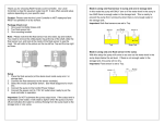
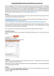
Reef Angel Controller Demo Software Simple V1.6 Copyright 2010 – Reef Angel All Rights Reserved The product and the information contained herein are subject to change without notice. This manual may not, in whole or in part, be reproduced or transmitted in any form either electronically or mechanically, including photocopying and recording, without the express written consent of Reef Angel. Important Safety Instructions PLEASE READ AND FOLLOW ALL SAFETY INSTRUCTIONS BEFORE PROCEDING DANGER Discontinue use if any signs of water are present in any electronic/electrical device. WARNING – To avoid injury to yourself and others, safety precautions should always be observed. DANGER – Never attempt to service any electronic /electrical equipment before unplugging the device from the outlet. Risk of electrical shock if care is not taken. Special care should always be taken when operating any aquarium equipment. If the plug or receptacle gets wet, NEVER unplug it from the outlet. Always use the fuse or circuit breaker that supplies power to the device. Disconnect it and then examine for water presence. If device shows any sign of abnormal appearance, discontinue use. Never operate the device if plugs or cords are damaged, torn, ripped or malfunctioning. A “drip loop” should be arranged and position your aquarium stand and tank to the side of the power receptacle to avoid the device or power receptacle from getting wet. Please refer to Figure 1 below. Figure 1 The Controller Demo software (Simple) comes pre-loaded with your Reef Angel Controller Kit. You can skip the next section if you have not uploaded any custom/modified software yet. This software is provided to you as a source code. Please read the open source license for more information on its use. Loading the controller demo code 1. 2. 3. 4. Please follow the instruction on the User Manual or at http://www.reefangel.com/Support.Setting-upyour-PC-computer.ashx on how to setup your computer. Make sure the Reef Angel Controller is powered up. Connect the TTL level converter cable to your PC. Connect the TTL level converter cable to your Reef Angel Controller. Note: Make sure you connect the cable as the picture above. Failure to do so can lead to damage to your Reef Angel Controller head unit and/or cable. 5. 6. 7. 8. 9. 10. 11. 12. 13. Open the Arduino Environment software. Download the latest Reef Angel Controller Demo Software (Simple) source code at http://www.reefangel.com/download.aspx Unzip the file to a known location, such as Desktop or My Documents. In the Arduino Environment software, click the menu “File -> Open” Locate and select the file you unzipped in the step 13 and click Open The source code will appear in the screen Make sure you have “Arduino Duemilanove or Nano with ATmega328” or “Reef Angel Controller” selected under the menu “Tools -> Board” Click the menu “File -> Upload to I/O board” You will see the Status LED blinking for several seconds and the software will start automatically after it is uploaded. Outlet socket assignment Socket 1: Auto top-off pump Socket 2: Moonlight lights Socket 3: Actinic lights Socket 4: Daylight lights Socket 5: Wavemaker pump 2 Socket 6: Wavemaker pump 1 Socket 7: Skimmer / General use pump Socket 8: Return pump 1st Generation 2nd Generation Summary of functions Feeding mode Water Change Mode View Log Date and Time Dawn and Dusk Lights Overheat LED PWM Control ATO Timeout Wavemaker Temperature Sensors Dump Log to PC Dump Parameters to PC Calibrate PH Probe Setting up your device To access the menu, simply push the thumb joystick down. Use the thumb joystick to navigate through the menu options. 1. Feeding Mode The feeding mode function is used when it is time to give some little perks to your corals and fishes. They love this time of the day! The controller will stop all pumps for 15 minutes and will show a countdown on the screen. When the timer is up, everything goes back to normal mode again. 2. Water Change Mode Similar to the feeding mode, this function will stop all pumps. Except that in this mode, there is no countdown. The controller will wait for you to resume normal mode. 3. View Log This function will display the last 10 log entries that were logged by the controller with timestamp and code. The following table shows all the log entries generated by the controller CODE 0 10 11 12 30 DESCRIPTION System Start-up Water temperature sensor defective Lights temperature sensor defective Room temperature sensor defective Auto top-off start Type Informational Alert Alert Alert Informational 31 32 40 41 42 43 44 45 50 51 52 53 54 61 62 71 72 Auto top-off stop Auto top-off timeout Daylight lights on Daylight lights off Actinic lights on Actinic lights off Moonlight lights on Moonlight lights off Water temperature too high Water temperature too low Lights temperature too high PH too high PH too low Feeding mode start Feeding mode stop Water change mode start Water change mode stop Informational Alert Informational Informational Informational Informational Informational Informational Alert Alert Alert Alert Alert Informational Informational Informational Informational Log entries are hard coded into the software and cannot be changed. If you have any special need and would like a simple modification of the coding, please email me at [email protected] so we can discuss the best way to accomplish what you need. A log entry is informational when it is a routine function that started or stopped. The alert type of log entry is an indicative that something is out of normal parameters and it requires user attention. Any event log that is considered an alert type will turn the status LED on to advise you that it requires your attention. The status LED will turn off only when you use the function "View Log". This will also clear any flag that was raised by the controller. Alert 10, 11 and 12 This flag is raised whenever the controller finds a missing or defective temperature sensor. It will then ignore future readings of that parameter until the issue has been resolved. Alert 32 This flag is raised when the timeout parameter in seconds entered in function 8 has passed. When this flag is raised, the ATO pump is turned off and will remain off until the flag is cleared. This will prevent your ATO pump to keep running and flood your tank in the event there is a malfunction with any of the float valves. Alert 50, 51, 53, 54 This flag is raised when the water parameters are not within the pre-determined range. Water Temperature range: 78 to 85°F PH range: 7.5 to 9.0PH Alert 52 This flag is raised when the maximum temperature entered in function 6 has been reached. This is mainly used for those that have LED lighting system and want to monitor heatsink temperature. When this flag is raised, the daylight and actinic lights are turned off and will remain off until the flag is cleared. They will not automatically come back on. 4. Date and Time Setup of calendar and clock settings. Once setup, these settings will remain in the memory in case of a power failure by a battery backup unit inside the controller. 5. Dawn and Dusk Setup of dawn and dusk time. Moonlight lights work in conjuction with this mode. They are programmed to turn on 1 hour prior to dusk and turn off 1 hour after dawn. This function has 2 operating modes and they are determined by the function 7 settings. Regular mode This mode is used whenever the PWM settings entered in function 7 are 0% for both daylight and actinic. This mode turn daylight lights on 30 minutes after dawn settings and turn them off 30 minutes prior to dusk settings. Within the first 30 minutes and the last 30 minutes, only actinic lights will be on. LED mode This mode is used whenever any of PWM settings entered in function 7 is different than 0%. This will indicate the controller that you have LED lighting system. In this mode, PWM is used to ramp up and down your LED lighting system. Within 1 hour after dawn and 1 hour prior to dusk, the controller will slowly ramp up/down the PWM to/from the specific setting entered in function 7. 6. Lights Overheat Range from 0 to 150°F Setup of maximum temperature allowed to operate daylight and actinic lights. This is mainly used by people with LED lighting systems who want to monitor heatsink temperature. When this temperature is reached, the daylight and actinic lights are turned off, an alert is generated causing the status LED to turn on and a code #52 is entered in the log. 7. LED PWM Control Daylight range from 0 to 100% Actinic range from 0 to 100% Setup of operating PWM settings for daylight and actinic LED lighting systems. On LED lighting systems with dimming capability, one way of controlling the intensity of light generated by the system is by using PWM signal. A change on the duty cycle of the PWM signal will cause the LED lighting system to change its intensity. These settings will determine which mode of dawn/dusk the controller will operate. Reef Angel Controller is capable of changing PWM duty cycle from 0% to 100%, but not all LED drivers are capable of dimming on the same. Some of them have a cutoff and will not dim any lower than 15%. The Meanwell driver ELN-60-48P is a good example. 8. ATO Timeout Range from 0 to 255s Setup of the maximum number of seconds that the ATO pump can remain on. If the ATO pump is on for this many seconds, Reef Angel Controller will turn the pump off and generate an alert causing the status LED to turn on and a code #32 is entered in the log. 9. Wavemaker Setup of the number of seconds and wave pattern that which each wavemaker relay has to wait before it switches on/off. The number of seconds in this setting is for half the cycle. For example, if you setup this setting to 100s, the relay will wait 100s to switch on and another 100s to switch off. 10. Temperature Sensors Setup of the temperature sensors. Each temperature sensor has a unique identifier, which is displayed in the screen. You can assign the sensor to start measuring water, lights or room temperature. 11. Dump Log to PC With the use of a TTL serial converter cable, you can send the log written in the Reef Angel Controller memory to the PC software. 12. Dump Parameters to PC With the use of a TTL serial converter cable, you can send the last 24 hours of parameters writen in the Reef Angel Controller memory to the PC Software. 13. Calibrate PH Probe Calibration of PH Probe requires 2 standards (one PH7 and one PH10). Place probe in the first standard and wait a few minutes or until it stabilizes, then place on the second standard and wait a few minutes or until it stabilizes. You can do either standard first. If you don't use the correct standards, the controller will just ignore the calibration and use the default settings. Note: The numbers shown in the screen are just for internal calculation and do not represent the actual PH.