1
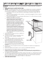
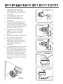
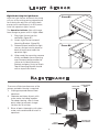
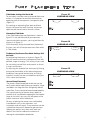
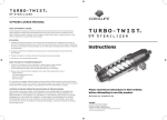
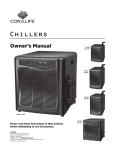
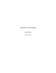
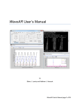
Wavemaker
Instructions
Please read these
instructions in their
entirety before
attempting to use
this product.
Coralife®
A product of Central Aquatics
(Division of Central Garden & Pet Co.)
Franklin, WI 53132 888.255.4527
Coralife® is a registered trademark of Central Garden & Pet
© 2010 Central Garden & Pet
DC2600 and DC5800
Important Safety Instructions
WARNING - To guard against injury, basic safety precautions should be observed, including the
following:
a) READ AND FOLLOW ALL SAFETY INSTRUCTIONS.
b) DANGER - To avoid possible electric shock, special care should be taken since water is employed in the use of aquarium equipment. For each of the following situations, do not attempt repairs by yourself; return the appliance to an authorized serivce facility or service or discard the appliance.
1. If the appliance shows any signs of abnormal water leakage, immediately unplug it from the power source.
2. Carefully examine the appliance after installation. It should not be plugged in if there is water on parts not intended to be wet.
3. Do not operate appliance if it has a damaged cord or plug, or if it is malfunctioning or has been dropped or damaged in any manner.
4. To avoid the possibility of the pump plug or receptacle getting wet, position aquarium stand and tank to one side of a wall-mounted receptacle to prevent water from dripping onto POWER SUPPLY
the receptacle or plug. A "drip loop" shown in CORD
the figure to the right, should be arranged by the user for each cord connecting an aquarium appliance to a receptacle. The "drip loop" is that part of the cord below the level of the receptacle, or the connector if an extension cord AQUARIUM
is used, to prevent water from traveling along cord and coming in contact with the receptacle. If the plug or receptacle does get wet, DO NOT unplug the cord. Disconnect the fuse or circuit breaker that supplies power to the appliance. Then, unplug and examine for presence of water in the receptacle.
c) Close supervision is necessary when any appliance is used by or near children.
d) To avoid injury, do not contact moving parts or hot parts such as heaters, reflectors, lamp bulbs
and the like.
e) Always unplug an appliance from an outlet when not in use, before putting on or taking off parts and before cleaning. Never yank cord to pull plug from DRIP LOOP
outlet. Grasp the plug and pull to disconnect.
f) Do not use an appliance for other than intended use The use of attachments not recommended or sold by the appliance manufacturer may cause an unsafe condition.
g) Do not install or store the appliance where it will be exposed to the weather or to temperatures below freezing.
h) Make sure an appliance mounted on a tank is correctly installed before operating it.
i) Read and observe all the important notices on the appliance.
j) If an extension cord is necessary, a cord with proper rating should be used. A cord rated for less amperes or watts than the appliance may overheat. Care should be taken to arrange the cord so that it will not be tripped over or pulled.
k) This appliance has a polarized plug (one blade is wider than the other). As a safety feature, this plug will fit into a polarized outlet only one way. If the plug does not fit fully into the outlet, reverse the plug. If it still does not fit, contact a qualified electrician. Never use with an extension cord unless plug can be fully inserted. Do not attempt to defeat this safety feature.
l) SAVE THESE INSTRUCTIONS.
2
Installation Instructions
1)
2)
3)
4)
5)
6)
7)
8)
Check pump for any signs of shipping damage. If damaged,
do not operate and return to place of purchase.
Insert pump onto suction cup mounting bracket (fig. A1).
Place pump in desired location
in aquarium.
To install pump securely, first push in firmly on mounting bracket to allow air to be removed from suction cup (fig. A2). Next, flip tab down to lock pump in place (fig. A3).
Plug the pumps into the ports labeled “1” and “2” on the top
of the Wavemaker controller
(fig. A4).
Plug the Wavemaker controller into the AC/DC converter (fig. A5).
Plug AC/DC converter into receptacle. Be sure cord makes a “drip loop” to prevent water from running down and into the receptacle.
If using optional tank mount bracket, position bracket (as shown in fig. A6) on wall in desired location. Mark screw holes with pencil. Drill small pilot holes on marks. Line up holes on bracket with pilot holes and insert screws into pilot holes. Mount wavemaker controller as illustrated in fig. A6.
Figure A1
Figure A2
Figure A3
Figure A4
Figure A5
Figure A6
3
Controller Settings
8
7
4
6
3
2
5
1
11) Settings Dial: Used to select one 51) Pump Power/Time Decrease:
of the four pump modes: #1 Continuous Flow mode, #2 Tidal mode, #3 Turbulence mode or #4 Turbulence/Continuous Flow mode
62) Set Button: Used to select which 22) Pump 1 Indicator: Indicates the amount of power flowing to pump 1 in Continuous Flow mode, or the amount of time pump 1 is at maximum power in Turbulence Mode
amount of power flowing to pump 2 in Continuous Flow mode, or the amount of time pump 2 is at maximum power in Turbulence Mode
reduces to slowest speed from normal operation for 30 minutes or until pressed again. Pump indicator LEDs will flash while the unit is paused.
84) Operation Indicator: Shows current 44) Pump Power/Time Increase:
pump to set the power level for
73) Feed Button: Pauses pumps and 33) Pump 2 Indicator: Indicates the Decreases the amount of power to the selected pump
Increases the amount of power to the selected pump
4
status if the controller - RED for paused, ORANGE for normal operation and GREEN for settings or night mode.
Programming the Controller
3)
4)
A) Continuous Flow Mode: Settings DIal Set to #1
In Continuous Flow mode, the amount of power set for each pump will remain constant.
1) Press the SET button. One LED light will show in the Pump 1 indicator. Using the Pump Power/
Time Increase and Decrease buttons, adjust the pump power up or down from 40-100% of maximum power. Each light indicates an additional 10% more power from 40%.
2) Press the SET button after setting power for Pump 1. Set power for Pump 2 the same way as Pump 1.
3) While setting, the Operation Indicator will blink red and green. If no new entries are made within 30 seconds, the pump will return to normal operation.
4) Press the SET button to begin.
B)
seconds (all lights lit) and goes up in 10 second intervals.
Press the SET button after setting timer for Pump 1. Set timer for Pump 2 the same way as Pump 1.
Press the SET button to begin.
D) Turbulence/Continuous Flow Mode: Settings DIal Set to #4
In Turbulence/Continuous Flow mode, Pump 1 will run at 40% power for five seconds, then build up to maxiumum power for the selected duration of time (10-60 seconds). Pump 2 will constantly run at the power level you have selected.
1) Press the SET button to select Pump 1.
2) Use the Pump Power/Time Increase and Decrease buttons to set the amount of time Pump 1 will run at full power. Timer ranges from 10 seconds (one light lit on the Pump 1 Indicator) to 60 seconds (all lights lit) and goes up in 10 second intervals.
3) Press the SET button. One LED light will show in the Pump 2 Indicator. Using the Pump Power/
Time Increase/Decrease buttons, adjust the pump power up or down from 40-100% of maximum power. Each light indicates an additional 10% more power from 40%.
4) Press the SET button to begin.
Tidal Mode: Settings DIal Set to #2
There is no user control for this mode. Pump 1 will run at full power while Pump 2 runs at low power. Every 12 hours, the two pumps will switch.
C) Turbulence Mode: Settings DIal
Set to #3
In Turbulence mode, the pumps will work at 40% power for five seconds, then build up to maximum power for the selected duration of time (10-60 seconds). A shorter amount of maximum power run time will increase water turbulence, while a longer time increases water flow, but decreases turbulence.
1) Press the SET button to select Pump 1.
2) Use the Pump Power/Time Increase and Decrease buttons to set the amount of time the pump will run at full power. Timer ranges from 10 seconds (one light lit on the Pump 1 Indicator) to 60 5
Light Sensor
Night Mode: Using the Light Sensor
With the Light Sensor attached, the pump
will run at the setting you've programmed
for it during the day, but will adjust both
pumps to run continuously at 40% power
when the aquarium lights are out.
Figure B1
The Operation Indicator light will change
from orange to green when in Night Mode.
1)
2)
3)
4)
Plug Light Sensor into the controller. (figure B1)
Attach Light Sensor to top of Mounting Bracket. (figure B2)
Determine best location for light sensor—for best results place on back of tank frame under the aquarium light.
When ready for mounting, remove all dirt and debris from mounting area. Remove tab from adhesive sticker on inside of Mounting Bracket and press firmly to attach. Top of Mounting Bracket should rest on top of tank frame.
Figure B2
Maintenance
To ensure efficient performance of the
pumps, periodic cleaning is required.
1)
2)
3)
SHAFT AND
BUSHINGS
Unplug pump and remove from aquarium.
Separate and clean all parts with warm water, including impeller. For deep cleaning, soak in three parts water to one part vinegar solution for 10 minutes.
Rinse all parts thoroughly with clean water, re-assemble and re-install in aquarium.
PUMP MOTOR
BODY
IMPELLER
IMPELLER CAGE
ASSIST
LEVER ARM
6
SUCTION CUP
ATTACHMENT
Pump Placement Tips
Figure C1
OVERHEAD VIEW
Tidal Mode: Settings DIal Set to #2
To accurately simulate natural wind and tidal wave
action, it is important to position the pumps on
opposite ends of the aquarium, facing each other
(figure C1).
overflow
overflow
By creating an alternating flow back and forth
across the face of the reef structure, the pumps
replicate tidal wave currents found in nature.
Alternative Tidal Mode
If the Tidal Mode pump configuration as shown in
figure C1 is not possible due to your aquarium
layout or aesthetic concerns, you may position the
pumps as in figure C2.
Figure C2
OVERHEAD VIEW
With the pumps facing outward from the back of
the tank, you will still create some cross flow while
in Tidal mode.
overflow
overflow
Turbulence/Continuous Flow Mode: Settings DIal
Set to #4
By positioning the pumps as shown in figure C3,
they will create a constant unidirectional flow with
periodic surges of energy. This setting is best used
for simulating natural flows and currents as found
in rivers and streams.
Figure C3
OVERHEAD VIEW
By adjusting the speed of the continuously flowing
pump and the duration of the alternating pump,
conditions from gentle lowland river to rushing
mountain streams can be simulated to match your
fish's natural environment.
overflow
General Pump Placement
The pumps should be placed where they can be
easily accessed for repositioning or removal. Algae
and debris can clog the inlets and greatly reduce
water flow, if not maintained and cleaned properly.
For a quick cleaning to remove heavy debris or
particles that may become trapped on the impeller
cage, or the inlets, you may shut off power to the
pumps and clean with a toothbrush.
Be wary of placing the pumps near soft-bodied
invertebrates such as sea anemones, sea
cucumbers and soft corals. These creatures can be
sucked into the pump if allowed to get too close.
Keeping the pumps away from rock work and
décor in the tank can reduce the chances of
damage to soft-bodied invertebrates.
7
overflow
Circulation Pumps
Limited Lifetime Warranty
WHAT THE WARRANTY COVERS:
Central Aquatics (Company) warrants this Coralife product (see Exclusions below) to the original
purchaser against defective material and workmanship that occurs during normal in-home use for
the life of the product. Company will, at Company’s option, either repair or replace same without
charge (but no cash refunds will be made). This warranty is limited to replacement or repair of
product only and does not cover loss of aquarium life, personal injury, property loss, or damage
arising from the use of the product.
EXCLUSIONS:
1. Damage resulting from accident, misuse, abuse, lack of reasonable care, subjecting the product
to any but the specified electrical service, other than the normal and ordinary use of the
product, subjecting the product to abnormal working conditions or any other failure not
resulting from defects in materials or workmanship.
2. Damage resulting from modification, tampering with or attempted repair by anyone other than
the Company.
3. Transfer of product to someone other than the original consumer or purchaser.
WHAT YOU MUST DO TO ENFORCE WARRANTY:
Contact the Company by telephone:
888-255-4527
Or contact the Company by writing:
Central Aquatics
5401 West Oakwood Park Drive, Franklin, WI 53132
Attn.: Warranty
You must pay any postage, shipping charges, insurance costs and other expenses to return the
product along with the original cash register receipt to Central Aquatics. However, if the necessary
repairs are covered by the warranty, Company will pay the return shipping charges to any
destination within the United States or Canada.
LIMITATION OF IMPLIED WARRANTIES AND EXCLUSION OF CERTAIN DAMAGES: THE
COMPANY DISCLAIMS LIABILITY FOR INCIDENTAL AND CONSEQUENTIAL DAMAGES FOR
BREACH OF ANY EXPRESS OR IMPLIED WARRANTY, INCLUDING ANY IMPLIED WARRANTY OF
MERCHANTABILITY, WITH RESPECT TO THIS PRODUCT. THIS WRITING CONSTITUTES THE
ENTIRE AGREEMENT OF THE PARTIES WITH RESPECT TO THE SUBJECT MATTER HEREOF; NO
WAIVER OR AMENDMENT SHALL
BE VALID UNLESS IN WRITING SIGNED BY THE COMPANY.
Some states do not allow the exclusion or limitation of consequential damages, so the above
limitation or exclusion may not apply to you.