1
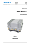
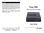
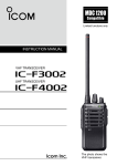
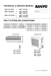
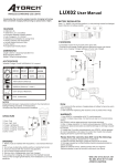
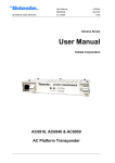
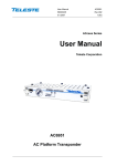
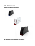
AC-ASP 8000
Access Control
System
AC
C
Single door to multi
door controlled
S
ES
LAN and/or WAN
connection
C
SE
Plug ‘n’ Play directly
in to a laptop,
desktop or tablet
Windows Based
R
U
Instant
adding/deletion of
users
Y
IT
20,000 users
100,000 offline
transactions
Multiple Users
Password Management
C
U
D
O
PR
Multiple Reports to Excel
Access monitoring
(Entry/exit)
Time & Attendance
TS
Timed Profiles
Timed Door Open
LT
Real Time Monitoring
D
Fire Alarm Input
Keypad Operation
Master PIN Code
Instant Lock Out
Anti-Tail Gate
And much more……..
Index
Connection & Drawings
Pages 2 - 5
Login & main software interface layout
Page 6
AC
Changing login password & Software registration
Page7
C
Add controllers
Pages 8 – 10
S
ES
Basic (Without hub or router required), LAN or WAN connection
Access Control
Page 11
Edit/rename doors & lock status
Page 12
C
SE
Check/test controller communication
Adding users and/or departments
Pages 13 – 15
Creating access privileges for users
Pages 16 – 17
U
Editing access privileges for users
Page 19
Y
IT
Query card/fob user records
R
Amending lost cards/fobs
Page 18
Page 20
Monitoring user access & location of users
Extended functions (Password required)
PR
Database backup & restore
Interlock
Pages 34 - 42
Pages 43 - 46
Page 47
Page 48
Pages 49 - 50
LT
Task list (Automatic door control opening)
Pages 31 – 33
TS
Anti-passback
Pages 28 – 30
C
U
D
Peripheral configuration (Fire alarm interface & regulations)
Page 27
O
Time profiles for users, departments & doors
Keypad operation
Pages 21 – 26
Pages 51 - 57
Meal setup
Pages 58 - 62
D
Attendance (Time & Attendance & reports)
1
Typical Layout Drawing
For illustration purposes, the yellow wire for the door reader/s is white
RED WIRE - +12v
BLACK WIRE - GND
GREEN WIRE - DATA OUT
WHITE WIRE - DATA IN
BROWN WIRE - LED
YELLOW WIRE - SOUND
C
AC
S
ES
C
SE
TS
C
U
D
O
PR
2) Ethernet
cable from
AC8000 to
router
Y
IT
R
U
1) Ethernet
cable from
AC8000
direct to PC
D
LT
2
AC8001 (One) Door Controller
For illustration purposes, the yellow wire for the door reader/s is white
C
AC
S
ES
C
SE
Y
IT
R
U
TS
C
U
D
O
PR
D
LT
3
AC8002 (Two) Door Controller
For illustration purposes, the yellow wire for the door reader/s is white
C
AC
S
ES
C
SE
Y
IT
R
U
TS
C
U
D
O
PR
D
LT
4
AC8001/2 Door Controller
Standard connection of a fire alarm input (Optional alarm Board)
C
AC
S
ES
C
SE
Y
IT
R
U
TS
C
U
D
O
PR
D
LT
5
Login
When you first activate the software, it will ask you for a User Name and Password, by default the user name is
“abc” and the password is “123” (without speech marks)
C
AC
S
ES
C
SE
U
Once the user name and password have been entered correctly, you will be displayed with the main interface
screen. At the top left hand side you will see the three main “Getting Started” buttons to set you up and running
in less than 15 minutes. This particular interface can be hidden or deactivated at any time by clicking Tools/Auto
Login
Y
IT
R
A majority of the main buttons also have short cuts to their relevant features by right clicking your mouse button
TS
C
U
D
O
PR
D
LT
6
Change Password
Tools/Edit Operator
If you wish to change the user name and password, click Tools/Edit Operator
You can also bypass the manual login procedure by clicking Tools/Auto Login
C
AC
S
ES
C
SE
Y
IT
R
U
Forgotten user name and password
In the event that you cannot remember your user name and password to login in to the software, please contact
you supplier who will give you full instructions as to what is required. It may take up to 24hrs to reset your
software and a charge may be incurred for this service
TS
C
U
D
O
PR
Software Registration
Help/About
The software provides a timed evaluation period of approximately three months before it expires, in order to
continue the full use, please ensure you register the software. Enter the relevant details and registration code
which can be obtained from your supplier
D
LT
7
Add Controller/s – LAN or WAN Connection
LAN Connection – Local Area Network via hub, router or directly to a PC or laptop
In order to add the access controller/s to the software, simply Click Add Controller By Searching located on the
top left hand side. The software will then locate the controller and provide the required details for you
automatically. This procedure is also required if/when adding additional controllers
You will then be displayed with this screen confirming the controller information. Click Add Found To Database
followed by Close to confirm
C
AC
Click Configure if you require W AN Connection
Port Forwarding is required to be setup for W AN Connection via your hub or router
S
ES
C
SE
Y
IT
R
U
TS
C
U
D
O
PR
D
LT
8
LAN Connection (Local Area Network)
Revert to the main screen and click Configuration/Controllers/Edit and choose Small Network for LAN
communication or Medium/Large Network if you require to control the system via Internet communication
Click Next and you can edit the door names and control status of the doors. When complete, press OK
C
AC
S
ES
C
SE
Y
IT
R
U
TS
C
U
D
O
PR
D
LT
9
WAN Connection (Wide Area Connection)
Revert to the main screen and click Configuration/Controllers/Edit and choose Medium/Large Network for
WAN communication via Internet connection
Port Forwarding is required to be setup for W AN Connection via your hub or router
C
AC
S
ES
C
SE
Y
IT
R
U
TS
C
U
D
O
PR
D
LT
10
Check Communication
When the controller/s have been added to the software click Operation. Right click on the door icon and choose
Check to test the communication between the software and the access controller. You will see a similar image as
below. Click on the Clear Event Window to clear the screen if required. Click Adjust Time followed by
Download to ensure time sycnronisation is correct between the computer and the access controller
C
AC
Upload/Download – ! Important !
Operation/Console/Download
Ensure that you download any changes/edits made to users, door settings or any other setting to the controller
Whilst the changes will be stored within the software database, the controller will not respond to these changes
unless you download them to it. To do this, click Operation/Console/Download Don’t forget to highlight the
door/s
S
ES
C
SE
Y
IT
R
U
TS
C
U
D
O
PR
D
LT
11
Edit door names & Lock status
Configuration/Controllers/Edit
Edit the door names and control status of the doors
Control: Is normal PC control status
Open: Will keep the door open (Treat this facility with care)
Close: Will keep the door locked (Treat this facility with care)
C
AC
S
ES
C
SE
Y
IT
R
U
TS
C
U
D
O
PR
D
LT
12
Adding Departments/Branch/Users/Access Privilege
Configuration/Departments/Add Top
You can create departments and/or branches if required. Enter the name for the department/s and then click OK
C
AC
S
ES
C
SE
Y
IT
R
U
TS
C
U
D
O
PR
D
LT
13
Adding Personnel
Configuration/Personnel
There are four ways in which users can be added to the system, this can be undertaken individually, via a USB
desktop reader, the door reader itself or manual batch input (Manual batch input requires sequential card
numbers)
* USB desktop card reader or door reader Must be used if adding key fobs
** You must issue all new card users Access Privileges before they can access any door/s
AC
To manually enter a card, Click the Add button and insert the 8 digit Wiegand number printed on the right hand
side of the card in to the Card No box and a photo of the user if required
C
Click on Auto Add if using a USB desktop card reader or door reader to enter a card
S
ES
Click Others to allow you to add extra information for the user if you wish
Click OK to exit or Add Next to add more users
C
SE
Y
IT
R
U
TS
C
U
D
O
PR
D
LT
14
C
AC
S
ES
C
SE
Y
IT
R
U
TS
C
U
D
O
PR
D
LT
15
Access Privileges
Configuration/Personnel
In order to allow users through the door/s you need to allocate an Access Privilege
There are two ways to do this, individual users, multiple users and/or by departments
Highlight a user and click Privilege. Using the >> arrow button/s, select the door you wish the user to access
and move it to the right hand side. Once complete, click Confirm And Download
C
AC
S
ES
C
SE
Y
IT
R
U
TS
C
U
D
O
PR
D
LT
16
C
AC
S
ES
C
SE
Y
IT
R
U
TS
C
U
D
O
PR
D
LT
17
Configuration/Personnel
To change the privileges of multiple users and/or by departments, click Access Privilege/Change Privileges
Using the >> arrow button/s, select the user/s or department and move them to the left hand side. Do the same
for the door/s. Once complete, click Allow And Download
C
AC
S
ES
C
SE
Y
IT
R
U
TS
C
U
D
O
PR
D
LT
18
Lost User Card
Configuration/Personnel/Card Lost
It is very easy to locate and rectify a lost user card, navigate to the main software interface screen and click on
Configuration/Personnel/Card Lost
This screen will appear and you simply choose the card user or department for the lost card, issue and enter a new
card number for the user and then click OK
C
AC
S
ES
C
SE
Y
IT
R
U
TS
C
U
D
O
PR
D
LT
19
Query Swipe Records
Operation/Query Swipe Records
Query Swipe Records will maintain 100,000 OFFLINE transactions for all activity. You can filter this information
by users, departments or date/time. This record cannot be deleted, however, it can be printed or exported to an
Excel spread sheet
C
AC
S
ES
C
SE
Y
IT
R
U
TS
C
U
D
O
PR
D
LT
20
Monitoring
Operation/Console/Upload and Monitor
Highlight a door and click Upload and Monitor. This will allow you to monitor real time activity and also upload
the very latest transactions to your computer that can be viewed by clicking Query Swipe Records
You can click on any user for individual information that will be displayed on the right side of the screen, however,
if you want to find the exact location of each user or even who is presently inside or outside the building, right click
the door and choose Location or Persons Inside
C
AC
S
ES
C
SE
Y
IT
R
U
TS
C
U
D
O
PR
D
LT
21
Location
The Location box will appear and you can filter this by either a user or department. Highlight a user and click
Query. We know that Andy had entered the building and exited and also how long he stayed for
C
AC
S
ES
C
SE
Y
IT
R
U
TS
C
U
D
O
PR
D
LT
22
We know that Kev has not exited the building
C
AC
S
ES
C
SE
Y
IT
R
U
TS
C
U
D
O
PR
D
LT
23
Persons Inside
The Persons Inside box will appear box. You can Auto Refresh Cycle this and find out who is inside, who is
outside or via a department. This shows three people inside
C
AC
S
ES
C
SE
Y
IT
R
U
TS
C
U
D
O
PR
D
LT
24
However, Dan has just exited the building which is displayed via the Auto Refresh Cycle of Persons Inside and
Persons Outside which is transaction number 4 and also confirmed by the right hand screen in the back ground
Click on Outside to double check
C
AC
S
ES
C
SE
Y
IT
R
U
TS
C
U
D
O
PR
D
LT
25
This confirms that Dan is now outside
C
AC
S
ES
C
SE
Y
IT
R
U
TS
C
U
D
O
PR
D
LT
26
Backup Database & Restore
File/DB Backup
The software will auto backup the database when you exit the software, however, it is recommended to manually
backup the database by clicking File/DB Backup and choose your required backup folder
This will be required in the event you need to re-install the software but do not wish to re-enter all the user data
You would simply copy and paste the database called iCCard3000 from your backup folder in to the newly
installed AccessControl folder
C
AC
S
ES
C
SE
Y
IT
R
U
TS
C
U
D
O
PR
D
LT
27
Extended Functions
Tools/Extended Functions (Password is 5678)
The extended functions provide six sections offering a multitude of additional options to suit your own
requirements as can be seen below. When you have chosen the options, you will be required to restart the
software and the new options will be displayed. Under the main head sections will also display the shortcuts to the
facility required (Right click mouse)
C
AC
S
ES
C
SE
Y
IT
R
U
TS
C
U
D
O
PR
D
LT
28
C
AC
S
ES
C
SE
Y
IT
R
U
TS
C
U
D
O
PR
D
LT
29
C
AC
S
ES
C
SE
Y
IT
R
U
TS
C
U
D
O
PR
D
LT
30
Time Profile
Configuration/Time Profile/New
Time Profile provides up to 255 time profile ID’s with three timed segments which can be allocated to individual
controllers, door readers, users, or departments. The example below shows how to link one profile to another
Enter the name of the profile in the Description box and choose an Activate/Deactivate, Time Segment and
Week Day as required
C
AC
You will notice that our Time Profile ID 2 is linked to Linked Time Profile 3. This is because users will also
require access during the weekend
S
ES
C
SE
Y
IT
R
U
TS
C
U
D
O
PR
D
LT
31
Note that you do not need to link Time Profile ID 3. When complete, click
Configuration/Access Privilege/Change Privileges to allocate the timed profiles
C
AC
S
ES
C
SE
Y
IT
R
U
TS
C
U
D
O
PR
D
LT
32
Using the >> arrow button/s, select the user/s or department and move them to the right hand side. Do the same
for the door/s. Once complete, click Allow And Download
C
AC
S
ES
C
SE
Y
IT
R
U
TS
C
U
D
O
PR
D
LT
33
Alarm Board (interface)
**Fire Regulations
Please ensure you contact your local Fire Officer with regards to the inter-connection of access control equipment
to your fire alarm system. More often than not, it will be acceptable to connect the fire alarm output to an
independent auxiliary relay or double pole emergency break glass switch in order to deactivate the locking devices
AC
The fire alarm panel manufacturer should always be contacted to ensure the auxiliary relays contained within the
fire alarm panel, which will release the door, are of a suitable quality for life safety.
C
S
ES
The AC-FAB (Alarm Board interface) is an add-on module for the AC8000 PC Access Control System designed to
accept a Normally Open contact input which then provides an alarm signal output via the software and/or
activating any of the four timer relays provided in addition to ensuring the door/s are held in the unlocked state for
as long as the alarm input is present (Certain features of the AC-FAB w ill also require an RFI D k eypad
and locking device fitted w ith door m onitoring contacts) It can also accept additional inputs to activate
individual relays as and when required
C
SE
It has a simple software interface that can be configured to your own requirements supporting one manual
Normally Open trigger input from an alarm system or emergency break glass switch, four timer relay outputs from
0 – 6000 seconds (1.66hrs), all providing Normally Open and Normally Closed outputs that can be connected to
external sounders, flashing beacons or any other device requiring a volt free contact input. Six triggering options
are available that can be programmed to activate one or all four relays
U
Y
IT
R
It supports and registers via the software an emergency threat PIN code (RFI D K eypad is required for this) , if
the door is open too long, door forced open, invalid card used, fire alarm and forced lock
TS
C
U
D
O
PR
D
LT
34
Alarm Board (interface)
C
AC
158l x 43w x 15h
Four x relays providing normally open/closed contacts
S
ES
A Normally Open trigger
is required to activate
C
SE
Y
IT
R
U
Connection port to the AC8000 controller
TS
C
U
D
O
Relay output
LED (Yellow)
PR
Power input
LED (Red)
D
LT
35
Example of the AC-FAB being activated by the alarm input, but also triggering one of the four relay outputs to
activate a strobe light from 0 – 6000 seconds (1.66hrs)
The alarm input will keep the door/s unlocked until it has been reset (Providing the Normally Open input is not
removed)
C
AC
S
ES
Alarm input
C
SE
Y
IT
R
U
TS
C
U
D
O
PR
D
LT
36
AC
Peripheral
Configuration/Peripheral
The auxiliary relay board (Fire Alarm Board interface) has one manual Normally Open trigger input, two triggering
sources (Door or ARM **) and four timer relay outputs from 0 – 6000 seconds (1.66hrs), providing Normally
Open and Normally Closed outputs that can be connected to external sounders or flashing beacons etc. In addition
to this, there are six triggering options that can be programmed to activate one or all four relays
C
The example below shows the standard (Door) configuration setup requiring the software to display when the
door is open too long, if the door has been forced open, if an invalid card is being used to gain entry, if the alarm
input has been activated and if a threat code has been used
S
ES
In order to program the relay outputs, click Hardware Configuration. We have set relay output one to activate
for 10 seconds
C
SE
Y
IT
R
U
TS
C
U
D
O
PR
D
LT
37
C
AC
ARM **
The Auxiliary Relay Method option allows for additional inputs that can be used in conjunction with the
standard DOOR cofiguration setup or independently to trigger the relay outputs (Non timed) and hold them open
until the input has been reset, all of which can be configured by clicking the OPTION button
This example will trigger a Fire Alarm event via the software only and no relays will activate on the
AC-FAB
S
ES
C
SE
Y
IT
R
U
TS
C
U
D
O
PR
D
LT
38
This configuration will trigger a Fire Alarm event via the software and also activate relay output number 1
indefinitely on the AC-FAB until the trigger is reset
Please note that options EXTA1/2/3 do not function on the AC-FAB
C
AC
S
ES
C
SE
Y
IT
R
U
TS
C
U
D
O
PR
D
LT
39
This configuration will trigger a Fire Alarm event via the software, the door status (Open or closed) as well as the
exit button being pressed and activate relay output number 2 indefinitely on the AC-FAB until the trigger is reset
C
AC
S
ES
C
SE
Y
IT
R
U
PR
TS
C
U
D
O
Option Button
An additional three options are provided as to what the relay output does for the timed duration which can be set
from 0 - 6000 seconds (1.66hrs) or if using the ARM option, there are five possible signal inputs available
D
LT
40
Here you can see the relevant ‘Trigger’ input is displayed via the software
This example shows that Sam has entered the building, the door opens, but it is open for too long. We close the
door, however, an invalid card is then presented to the door, followed by a forced entry. We then close the door
again. The fire alarm then activates followed by the threat code
C
AC
S
ES
C
SE
Y
IT
R
U
TS
C
U
D
O
PR
D
LT
41
Change Threat Code
A keypad is required for this and in the event of a threat or emergency access is required, the user would enter
this number exactly without any prefix or suffix in order to gain entry. The threat code can be changed to any 6
digit number required
All users can enter this number. It cannot be ‘Privileged’ to individual users or departments, therefore, treat this
function carefully and who you issue the code number to
C
AC
S
ES
C
SE
Once you are happy with the settings, ensure you download to the controller. Click
Operation/Console/Download. If you wish to monitor the results, click Upload and Monitor
Y
IT
R
U
TS
C
U
D
O
PR
D
LT
42
Keypad Operation (PWD MGT)
Configuration/PWD MGT
A Wiegand keypad will provide more stringent access for all users and/or staff which can be used in four ways:
Card + PIN code
Card only
Wiegand PIN code
Master PIN code
AC
Within the Password Management screen are four sub-sections, Card + PIN, PIN Code, Controller’s Password
and Manual Input Password. Tick each door required for keypad operation
C
S
ES
C
SE
Y
IT
R
U
TS
C
U
D
O
PR
D
LT
43
PIN Code
The PIN Code screen will display all users or you can filter this to individual departments. The default PIN code for
all users/departments is 345678 and displayed as ‘UnChanged’
Change PIN will of course allow you to enter a new 4-6 digit PIN code for each user and will be displayed as
‘Changed’. If you do not enter anything at all, it will display ‘No Password’
C
AC
! Important !
Please ensure you make a note of all allocated PIN numbers for users. The software will not display the user PIN
number at all
In the event that you have lost user PIN numbers, you can either manually change them or please contact you
supplier who will give you full instructions as to what is required. It may take up to 24hrs to provide your original
user PIN numbers and a charge may be incurred for this service
S
ES
With the configurations we have set in the below example (Changed/UnChanged & No Password) will be as
follows:
C
SE
1) Andy & Kev must present their ‘Card + PIN + #’ in order to gain access
2) Dee & Dan must present their ‘Card + (Default PIN 345678)’ in order to gain access (# is not required)
3) Sam, Mick & Dave can present their ‘Card’ or enter ‘* + the 8 digit Wiegand number on their card + #’
in order to gain access
Y
IT
R
U
TS
C
U
D
O
PR
D
LT
44
Controller’s Password
Master PIN codes can also be created for senior staff up to a maximum of 4 PIN codes per door – Users and
Master PIN codes can be 4-6 digits
Enter ‘PIN + #’ in order to gain access
C
AC
S
ES
C
SE
Y
IT
R
U
TS
C
U
D
O
PR
D
LT
45
Manual Input Password
Users who have a ‘No Password’ can present their ‘Card’ or ‘* + the 8 digit Wiegand number on their card
+ #’ in order to gain access
C
AC
S
ES
C
SE
Y
IT
R
U
TS
C
U
D
O
PR
D
LT
46
Anti-Passback
Configuration/Anti-Passback
Anti-passback is a secure feature requiring a card reader for entry and exit in order for it to function correctly. This
facility prevents a card or PIN code from being used twice to gain access through a door without it being used to
exit a door. This prevents users who gain access, then “Passback” their card to another user to gain entry at a
later time. An ideal feature for health clubs, gyms or social clubs who may charge an annual fee for membership
C
AC
S
ES
C
SE
Y
IT
R
U
TS
C
U
D
O
PR
D
LT
47
Interlock
Configuration/Inter Lock
You can create an inter lock facility whereby one door is open and the second door is closed. The second door will
not open until the first door is closed (You will require standard door contacts for this or a monitored magnetic
lock or monitored lock release fitted with monitoring door contacts)
(Not available on single door controllers)
C
AC
Door Contacts: Door contacts connected to the control board will inform the software as to the actual status of
the door in question, in this way, the software can detect if the door is in a physical open or closed state,
regardless if the locking device is actually locked or unlocked
S
ES
C
SE
Y
IT
R
U
TS
C
U
D
O
PR
D
LT
48
Task List
Configuration/Task List
This option is for setting times of the day and/or days of the week where you require to control the door status
automatically, for example, a School may require the door/s to open first thing in the morning or perhaps a
Hospital requires absolute no access for door/s of a night time
Click on the Task drop down menu button to display a variety of available options which can be adapted to
individual or all doors
C
AC
A maximum of 64 settings can be made and can be edited at anytime
S
ES
C
SE
Y
IT
R
U
TS
C
U
D
O
PR
D
LT
49
This example shows all doors will open at 07.00am and then reverting to door controlled status at 07.30am for one
day only
Choose an activation and deactivation date, an activation time, day of the week, which door the task should be
adapted to and finally choose a task. When complete, click Add
C
AC
S
ES
C
SE
Y
IT
R
U
TS
C
U
D
O
PR
D
LT
50
Attendance/Manual Sign In
Attendance (Time Attendance) literally operates in the background for all users and departments and allows you to
create daily and annual leave, work shift hours and manual sign in for individual users and/or departments for
specific days and time. Complex, simplified or filtered reports can be printed directly to your printer or exported to
Excel
Please ensure: User privileges are set for Attendance
AC
Manual Sign In will provide an ON DUTY time for users or departments within the reports. This will only be
required if you have temporary staff for example, if not, then you do not need to enter any details
C
Click the +Add button to create a new Manual Sign In, select the users or departments on the left and then
using the >> arrow button/s, move them to the right. When complete, click Add followed by Close
S
ES
C
SE
Y
IT
R
U
TS
C
U
D
O
PR
D
LT
51
Leave/Business Trip
This will allow you to allocate business, sickness and private leave for users and/or departments
You can also create your own title by clicking on Type Setup
Click the +Add button to create a new “Leave”, select the users or departments on the left and then using the >>
arrow button/s, move them to the right. When complete, click Add followed by Close
C
AC
S
ES
C
SE
Y
IT
R
U
TS
C
U
D
O
PR
D
LT
52
Type Setup
Create your own “Leave” title by clicking Type Setup/Add/New Name
When complete, click OK
C
AC
S
ES
C
SE
Y
IT
R
U
TS
C
U
D
O
PR
D
LT
53
Holiday
This will allow you to allocate Company leave such as Easter, Christmas, New Year, Bank Holidays or whatever you
choose. This will be displayed on the reports as a * for each user/department
C
AC
S
ES
C
SE
Y
IT
R
U
TS
C
U
D
O
PR
D
LT
54
Normal Shift Rules
This will allow you to allocate normal working hour start and finish times as well as an amount of time from 1 –
600 minutes for arriving late or leaving early. It also provides an advanced facility if required. Correctly setting
these options will generate a more enhanced Attendance Report such as time arrived, time arrived late, time left
and time left late
C
AC
S
ES
C
SE
Y
IT
R
U
TS
C
U
D
O
PR
D
LT
55
Attendance Report
Click Create to generate a report – up to date reports will require you to Upload the latest transactions in the first
instance. Click Operation/Console/Upload
The attendance report can be filtered by user or department for all or selected dates. Note that our user Dan is
required for manual sign in, this report shows he is required to sign in at 15.20pm, however, his sign in time was
15.36pm and he left early at 15.49pm by 31 minutes
AC
Right clicking on the report will allow you to select particular configure columns for preferred viewing which can be
saved
C
Query Option will allow you to view specific results of the report. The report can be printed directly to your
printer or exported to Excel
S
ES
C
SE
Y
IT
R
U
TS
C
U
D
O
PR
D
LT
56
Statistics
The statistics button will provide an individual report for days worked, lateness, early leave, sick leave, annual
leave and so on. This can also be printed or exported to Excel
C
AC
S
ES
C
SE
Y
IT
R
U
TS
C
U
D
O
PR
D
LT
57
Const Meal
The Meal Setup is primarily designed for charging entry and/or exit to an on-site or factory canteen to enable a
cost charge per user or department. The facility could be also used for any other requirement needing to make a
charge for entry and/or exit
You can allocate a fixed rate for entry or exit or even allocate a higher rate for individual door readers for special
occasions or “One off events” in addition to charging different amounts for certain times of the day
Click Meal Setup to begin
C
AC
S
ES
C
SE
Y
IT
R
U
TS
C
U
D
O
PR
D
LT
58
In the Meal Setup, you have three sections, Readers, Rules and Meal Period
Readers
Choose the door/s on the left and then using the >> arrow button/s, move them to the right. When complete,
click OK. Readers chosen will of course be chargeable when accessed
C
AC
Rules
There are three options
1) One swipe counts as one meal (Or entry)
2) More swipes within the same Meal Period as ONLY one meal (Or entry)
3) More swipes as one meal if the interval between them is less than the allocated time (With the Meal Period Default is 60 seconds)
S
ES
C
SE
Y
IT
R
U
TS
C
U
D
O
PR
D
LT
59
Meal Period
There are four timed options available for morning, lunch, evening and other. This is where you choose the
amount to charge for entry and/or exit
C
AC
Option
Choosing this option allows you to make an overridden cost for the selected door reader for either one or all of the
four timed options available
Choose the door/s on the left and then using the >> arrow button/s, move them to the right. When complete,
click OK
S
ES
C
SE
Y
IT
R
U
TS
C
U
D
O
PR
Department Method (According To Group)
Using the According To Group option allows you to make a single cost charge per department. Double click on the
‘Enable’ button to display an additional box allowing you to enter the desired amount to charge or disable the
department
When complete, click OK
D
LT
60
Meal Reports
Click Create to generate a report – up to date reports will require you to Upload the latest transactions in the first
instance. Click Operation/Console/Upload
The meal report can be filtered by user or department for all or selected dates and can be printed directly to your
printer or exported to Excel
C
AC
Examples: (1-3)
This example shows Mick entering twice (The default time for this particular example was 5 seconds) which has
incurred £2
S
ES
C
SE
Y
IT
R
U
TS
C
U
D
O
PR
2) This example shows Mick entering twice (We have used the Option box to make an overridden cost for the
selected door reader) which has incurred £10
D
LT
61
3) This example shows Mick entering twice (We have the option of Department Method (According To Group)
to make an overridden cost for the selected door reader) which has incurred £200
C
AC
S
ES
C
SE
Y
IT
R
U
TS
C
U
D
O
PR
D
LT
62