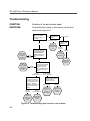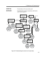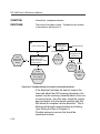
1
B
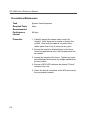
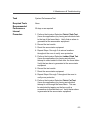
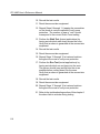
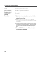
Terminating Optical Fiber
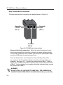
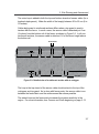
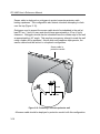
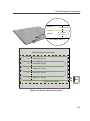
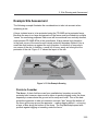
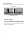
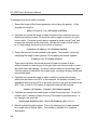
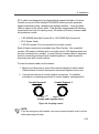
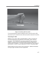
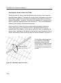
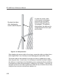
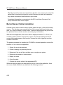
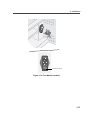
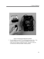
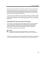
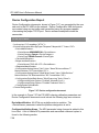
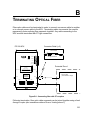
Fiber optic cable must be terminated in order to connect one sensor cable to another
or to connect sensor cable to the APU. Terminating cable circumvents the need for
permanently fusion splicing fiber segments together. Any cable connecting to the
APU must be terminated with ST-type connectors.
Connector Detail (x 2)
FD-332 APU
Sensor Cable
ALARM B
RS-232
DC 12-24 V
POWER
ALARM A
FAULT
TAMPER
12-24 VDC
12
11
10
9
8
7
6
5
4
3
GND 2
+1
Fiber SenSys, Inc.
Fiber Defender
FD-332 Alarm Processor
Anemometer
503-692-4430
Sensor Cable
(5 km Maximum Length)
CLASS 1
LASER OUTPUT
This product complies
with 21 CFR 1040.10
CH B
Protected Zone 1
Anemometer
Fiber Optic Intrusion Detection System
MADE IN U.S.A.
Output
ST-Type Connector
Power
Fault
Output
CH A
Event
Input
Alarm
Test
Input
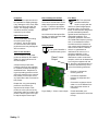
Figure B-1: Connecting fiber with ST couplers
Following termination, fiber optic cable segments can be joined together using a feed
through coupler (also sometimes referred to as a "mating sleeve").
B-1