1
March 2005
Clamp-on Transducer Problems (cont.)
2. MISALIGNMENT
The transducer transmits relatively narrow beams of ultrasound,
and therefore transducer alignment is critical to assure that the
beam can travel from one transducer to the other without undue
attenuation. Be sure to exactly follow the instructions that came
with your transducers and clamping fixtures. Also, be sure that
the transducer spacing agrees with the calculated spacing (S).
3. INTERNAL DAMAGE
Ultrasonic transducers consist of a ceramic “crystal” bonded to
the transducer case. The bond between the crystal and the case
may be damaged by extreme shock and by temperature extremes.
The crystal itself can also be damaged by the same conditions.
The internal wiring can be corroded or shorted if contaminants
enter the transducer housing.
4. PHYSICAL DAMAGE
Transducers may be physically damaged by dropping them onto a
hard surface or striking them against another object. Usually the
connector on the transducer is the part that is damaged, as it is the
most fragile. Minor damage may be repaired by carefully bending
the connector back into shape. If the connector cannot be
repaired, replace the transducers. Note that transducers must be
replaced in pairs, and that after replacement the flowmeter
parameters should be checked (see Chapter 3, Programming Site
Data).
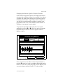
5. CYCLE SKIP CONDITION
A cycle skip is usually caused by a distorted or altered signal due
to poor couplant, bad wall, or unusual fluid disturbances. To
resolve a cycle skip, recouple both transducers with proper
couplant. Try standard CPL-1 couplant that is good to 212°F
(100°C) or CPL-2 for up to 500°F (260°C). In addition, make
sure the pipe wall is free of paint and rust.
Contact GE Infrastructure Sensing if you cannot solve a
transducer-related problem.
Diagnostics and Troubleshooting
9-13