1
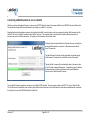
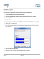
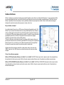
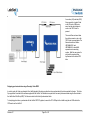
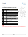
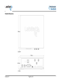
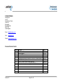
Instruction Manual LabSat 2 Multi Constellation GNSS Simulator Version 2.0 Contents Contents .............................................................................................................................................................................................. 2 Introduction ........................................................................................................................................................................................ 3 Operation ............................................................................................................................................................................................ 4 LabSat 2 Equipment ........................................................................................................................................................................... 5 Connector Overview .......................................................................................................................................................................... 6 PC Requirements ............................................................................................................................................................................... 7 Installing LabSat Software ................................................................................................................................................................ 7 Software Overview ............................................................................................................................................................................. 9 LabSat 2 Settings Menu ................................................................................................................................................................... 10 Recording GNSS Data with LabSat 2.............................................................................................................................................. 12 Recording Data with a Brake Trigger Input or other event ........................................................................................................... 18 Replaying GPS Data with LabSat 2 ................................................................................................................................................. 19 Converting LabSat Scenarios to run on LabSat 2 ......................................................................................................................... 26 LabSat Firmware Upgrade ............................................................................................................................................................... 27 SatGen v2 Software.......................................................................................................................................................................... 28 Interface Modules ............................................................................................................................................................................. 29 Video Synchronisation .................................................................................................................................................................... 30 Advanced Functions ........................................................................................................................................................................ 33 Troubleshooting Guide .................................................................................................................................................................... 34 LabSat Specifications ...................................................................................................................................................................... 36 LabSat Software Development Kit (SDK) ....................................................................................................................................... 37 Connector Pin Data .......................................................................................................................................................................... 38 Contact Details ................................................................................................................................................................................. 41 Revision 2.7 Page 2 of 42 Introduction The LabSat 2 is a dedicated Global Navigation Satellite System (GNSS) signal generator with RF record and playback facilities, enabling real world GNSS RF testing to take place in the laboratory. The LabSat is small and rugged, allowing it to be used in the field to continuously record the Global Positioning System (GPS), Galileo, BeiDou Navigation Satellite System (BDS) and GLONASS RF signals in a digital form which can then be replayed at a later date. LabSat 2 is ideal for almost any kind of GNSS development, e.g. GPS/Galileo/BDS/GLONASS engines, GNSS enabled Smartphones, Portable Navigation Devices (PND), tracking systems and much more. It is also very well suited to production line testing as it can represent a real world test as well as a carefully simulated scenario. LabSat 2 works with the GPS/Galileo L1 (1575.42MHz) signal, BDS B1 (1561.098 MHz) signal and GLONASS L1 (Channels 06 to -7 or approximately 1606MHz down to 1598MHz) signal and has no limit to the number of satellites that can be logged. In addition to recorded data, the Labsat 2 can replay simulated, GPS L1 and or GLONASS L1 scenarios generated using the optional Racelogic SatGen v2 software. Real world GNSS effects can be seen in test scenarios - Multipath - Drop-outs - Tree coverage - Adverse terrain effects - Atmospheric effects Revision 2.7 Page 3 of 42 Ability to replay data allows repeatable testing of GNSS receiver capabilities such as: - Sensitivity – Tracking and Acquisition - Time To First Fix (TTFF) – Cold, Warm and Hot Start - Position Accuracy and Repeatability - Tracking Accuracy and Repeatability - Reacquisition Time Operation Depending on model type, the LabSat 2 is able to record RF data directly from an active antenna and store the data on a hard drive or generate GNSS RF signals from data stored on a hard drive. There are three RF ports on the LabSat 2 these are marked CLOCK IN, RF IN, RF OUT. The RF IN socket is used to connect an active GNSS antenna when recording data. During recording, the RF OUT port is switched off to ensure that it does not interfere with the recorded data. The RF OUT port is used to connect the LabSat 2 to the GNSS system under test. The output signal of the LabSat 2 is at a nominal level of -83 dB when replaying previously recorded data. Using the PC software, it is possible to attenuate the LabSat 2 output by approximately 24dB giving a signal power range of -83 dBm down to -107dBm. Adjustment to the output attenuation is made using the slider controls which is accessed from the RF Attenuation tab in the LabSat software. With the slider positioned to the left on the screen, attenuation is 0dB meaning 0dB of attenuation on the nominal -83dBm output. As the slider is moved to the right, in 0.5 dB steps, the attenuation increases, and the RF output level is reduced accordingly. The tick boxes allow for each channel to be muted simulating GNSS dropout. See page 23 for details When replaying RF data into a GNSS engine, it may be necessary to increase attenuation in order for the GNSS engine to acquire satellite data. It is also important to note when replaying previously recorded GNSS data, that it may be required to cold start the GNSS engine under test. This is because GNSS engines often rely on downloaded almanac data to determine which satellites to look for at a given date and time. A cold start of the GNSS engine should clear any stored almanac data, forcing the GNSS engine to look for all satellites. Revision 2.7 Page 4 of 42 LabSat 2 Equipment Standard equipment Part Number RLLSx02-GNL1 LS02 LS02HDD RLVBACS020 RLCAB042 RLCAB066-2 RLCAB010L RLACS156 RLACS154 RLCAB071-1 RLCAB082-1 RLCAB083-1 RLCAB084-1 CDRLLS LS02MAN RLLSCAL Description LabSat 2 Main Unit LabSat Scenario Hard Disk Drive 500GB USB Drive Mains Power Supply USB ‘A’ to USB ‘B’ Lead - 2M USB ‘A’ to USB Mini ‘B’ Lead - 2M Power Cable - 2 Way LEMO to vehicle 12V socket GNSS Magnetic Mount Active Antenna (not applicable to replay-only LabSat 2) LabSat 2 Carry Case RG174 - 1M (SMA Plug to SMA Plug) Cable RG174 - 1M (SMA Plug to MCX Plug) Cable RG174 - 1M (SMA Plug to MMCX Plug) Cable RG174 - 1M (SMA Plug to TNC Plug) Cable LabSat Software CD LabSat 2 Manual Calibration Certificate Optional equipment Part Number RLLSIM01 RLLSIM02 RLLSIM03 RLLSIM04 RLLSSGSW02 RLLSSGSWG Revision 2.7 Description Interface Module for CAN Bus Input / Output Interface Module for RS-232 Input / Output Interface Module for RS-422 or RS-485 Input / Output Dual CAN Bus Interface Module SatGen v2 Software - GPS only scenario creation software. (Please contact your LabSat distributor or Racelogic for details) SatGen Software – GPS / GLONASS scenario creation software. (Please contact your LabSat distributor or Racelogic for details) Page 5 of 42 Connector Overview Connector DATA GPS MONITOR PWR AUX RF OUT RF IN CLOCK IN DIGITAL I/O Description High speed USB 2.0 link GPS Monitor - NMEA 12 Volt DC 5 Pin LEMO GNSS Simulation RF Output GNSS Active Antenna Input 10 MHz Reference 26 Way D-Type Connector Comment Transfers data to and from PC Outputs NMEA from internal GPS engine during Replay and Record Power Supply Input to LabSat 2 Digital In / Out – For connection of Interface Modules such as RLLSIM01 GNSS signal output during replay mode Used when recording GNSS signals External reference clock input 1 – PPS Output ( refer to Connector Pin Data section for further pin out details) LEDS PWR PLAY REC BUFFER Description Power status Replay Indication Record Indication Memory Buffer status Comment Green LED indicates power good Indicates that LabSat 2 is in Replay Mode Indicates that LabSat 2 is in Record Mode Indicates buffer status. If status reaches F (Full Buffer) during record or replay, this indicates that the PC cannot maintain the required transfer rate. Recorded data may be corrupt if full buffer occurs during record Revision 2.7 Page 6 of 42 PC Requirements The LabSat 2 uses a USB 2.0 HI-SPEED interface for data transfer. When recording RF signals, the sustained USB transfer rate is in excess of 8Mbytes/s. It is therefore important to ensure that all intensive background tasks such as anti-virus scans are switched off to avoid interruption of data transfer to and from the hard drive. It may also be required to configure the laptop power settings to ensure maximum processor speed when using battery power as it is common for laptop PCs to reduce their processing speed when running without an external power supply. Minimum recommended specification for the desktop or laptop PC to be used with the LabSat 2. ® Intel Core2™ Duo 1.8GHz 2GB RAM 250GB Hard Drive ® ® ® ® Microsoft Windows XP Pro or Windows Vista Business or Windows 7 Professional, Windows 8 Pro Minimum recommended specification for the desktop or laptop PC to be used with SatGen v2 software. ® Intel Core™ i5 2.27GHz 4GB RAM 250GB Hard Drive ® ® ® Microsoft Windows Vista Business or Windows 7 Professional, Windows 8 Pro Installing LabSat Software Configuration and control of the LabSat 2 is performed using the supplied LabSat Software. Before using your LabSat 2 it is necessary to install the software which also contains the USB drivers required for communication. Once this has been done the USB cables should be connected to the LabSat 2 prior to it being powered, this allows the configuration of the USB connection from LabSat 2 to the computer. When you connect to the LabSat 2 via USB for the first time you will be required to install USB drivers, please see the section ‘Connecting LabSat 2 USB’ below. Insert the supplied CD-ROM into the CD drive of your computer. An installation dialog will automatically appear; follow the onscreen instructions to complete the installation of the setup software. After installation the CD-ROM can be removed and an icon should have appeared on your desktop that will allow you to start the LabSat software. Revision 2.7 Page 7 of 42 Connecting LabSat 2 USB and installing drivers 1. Connect the USB A to B cable between the LabSat 2 and the computer. If you intend to use the GNSS monitor connect the Mini USB as well. 2. The computer should now recognise the presence of a new USB device; after a short period of time a ‘Found New Hardware Wizard’ window will appear. Click Next to continue the installation. 3. Click ‘next’, with the option ‘Install the software automatically (Recommended)’ Selected. (See image right) 4. At the last window click ‘Finish’ to complete the installation. 5. This process will then repeat a second time beginning with step 2. Now connect the LabSat 2 to its power supply. Your computer should now recognise the unit, and the USB connections will be recognised by the LabSat Setup software when started. Double-click the LabSat software icon to start the software See the Troubleshooting section if the installation process fails at any stage. Revision 2.7 Page 8 of 42 Software Overview The LabSat software is used to control record or replay functions of the LabSat. The picture below shows the LabSat Replay screen. Scenario File Name Stop Replay Replay Progress Bar Display Buffer Status Display Advanced Playback Control Start Replay Record Mode LabSat 2 Settings Display RF Attenuation Display Digital Noise GNSS Monitor Display Video Sync Serial Number of Connected LabSat and Options Revision 2.7 Page 9 of 42 LabSat 2 Settings Menu The LabSat V 2.2.0 software can be used to control the multi-GNSS LabSat 2, as well as LabSat hardware. When a LabSat is connected to the PC the LabSat software will auto-detect the type of hardware connected and configure LabSat accordingly. In the example shown, left, a LabSat 2 Replay and Record unit has been connected to the PC. The LabSat software has been started and the Settings menus accessed. LabSat 2 Replay and Record (010509) Revision 2.7 Hardware Settings: LabSat 2 is a Multi GNSS Replay and Record Simulator. Each Channel is selectable to record and replay from the GPS L1, Galileo E1, BDS B1 or GLONASS L1 RF signals. The system can be set to record a single constellation at 2 bit or in pairs at 1 bit and one constellation with the second channel set to record DIO. Setting channel A will determine which constellation can be used with the DIO. See channel mode in advanced recording control for detailed selection on page16. The Reference Clock can be set to use the optional OCXO (if installed) or the TCXO. If required external timing can be selected, either a 10MHz or 16.368MHz source. The Clock Output can be enabled or disabled for 16.368MHZ output to the 26 way connector. The GNSS Monitor is set to Internal LabSat 2. This uses the internal GPS engine to monitor GPS signals during Replay or Record, on the LabSat software GUI. The monitor can be set to Internal LabSat 2 (10Hz) which will use up to to eight satellites only in this mode. The NVS NVO8C setting refers to an external monitor for GPS & GLONASS signals. An external Serial Monitor may also be selected, to display NMEA data (if available) from the GNSS receiver under test (DUT) on the LabSat software. The GPS Monitor may also be disabled Note the Video Sync and Serial Proxy tick boxes. Video Sync allows for the synchronisation of the LabSat scenario with a video VBOX recording of the route. Serial Proxy allows for the serial NMEA data from the internal receiver to be redirected to another port. The Turntable Control is part of the LabSat Turntable application. Please contact your LabSat distributor or Racelogic for details. Page 10 of 42 The Upgrade Button is used for specific software upgrades such as input of data to allow for a Replay Only LabSat to be set up for a rental record period. Please contact Racelogic or your LabSat distributer for details. Note: The Upgrade Button is not to be used for firmware upgrades, please refer to the LabSat Firmware section on page 27. Upgrade button TXCO Reference Clock Selected Constellation selection Clock Output Selected Enable auto configuration of LabSat 2 Selected GNSS Monitor selected, Video Sync & Serial Proxy deselected Revision 2.7 Turntable control Page 11 of 42 Recording GNSS Data with LabSat 2 NB: Applicable to RLLSC02-GNL1 and RLLSR02-GNL1 LabSat 2 Models Only The GNSS antenna supplied with the LabSat 2 is a 3V active antenna with 28dB gain. For the best possible signal quality, it is important to maintain a good RF connection between the antenna and the LabSat. Before fixing the antenna to the LabSat, ensure that there are no dust particles in either connector. Replacement antennas are available by contacting your LabSat distributor. The antenna is a magnetic mounting type for quick and simple mounting to the vehicle roof. For optimum GNSS signal reception, make sure that the antenna is fitted to the highest point of the vehicle away from any obstructions that may block satellite reception. The GNSS antenna works best with a metal ground plane underneath (a metallic vehicle roof is perfect for this). Please also note that when using any GNSS equipment, a clear view of the sky, without physical obscuration, is important. Objects in the surrounding area such as tall buildings or trees can block the GNSS signal causing a reduction in the number of satellites being tracked, or introducing reflected signals that can decrease the accuracy of the system. Note that clouds and other atmospheric conditions do not affect the LabSat’s performance. GNSS antennae require a ground plane to operate correctly. This helps to reduce unwanted reflections of the GNSS signals caused by nearby objects, and usually the metal roof of a vehicle performs this function. However, if a test requires an antenna to be placed either off the vehicle, or on a vehicle that does not have a metallic roof, a special ground plane antenna must be used. This has an internal ground plane and can operate perfectly without the need for mounting on a metal surface. Ground plane antennas are available from your LabSat distributor. Revision 2.7 Page 12 of 42 The LabSat 2 is set up according to the diagram opposite. 1. Connect the Active GNSS antenna to the RF IN port of the LabSat 2. 2. Connect the high speed USB cable to the computer on which the Scenario data file is to be recorded. It is possible to connect an external USB drive to the computer and stream the recorded file directly onto this drive. 3. Connect power to the LabSat 2. 4. Start the LabSat software. Before recording Scenario data it is important to observe certain criteria, failure to follow these precautions may result in satellite data dropouts or corrupt data contained within the recorded file. Very Important: Running Background Applications if Logging to Computer The LabSat 2 has a two second USB buffer, but due to the exceptionally high data rates and processing power utilised by the LabSat 2 USB bus when recording GNSS data, it is important to have no other applications running on the computer and not to start any other applications whilst the LabSat 2 is recording data. Also make sure you do not start to move windows around, or do anything which takes processing power away from the LabSat 2 application, as Windows can occasionally stall for more than 2 seconds when launching/running other applications. Even though you may have multiple USB ports on your computer, in most cases they all share the same bus. Therefore try to limit any activity using additional USB devices. Recording Data to an External Drive: It is recommended that any external drive used to record scenarios is formatted in the NTFS format. The FAT32 format has a file size limit of 4 GB, which is equivalent to about 34 minutes of recording. The USB drives supplied with the LabSat 2 are pre-formatted using the NTFS file format. 5. Once the LabSat software is running, LabSat 2 is now ready to record data. 6. Click the Browse Button. The user will be prompted to enter the filename and choose the location of the recorded file. Revision 2.7 Page 13 of 42 7. Click the Record Button. The REC Light on the front panel of LabSat 2 will start to flash, indicating that LabSat 2 is recording GNSS RF data. 8. As the LabSat 2 begins to record data the Duration timer will indicate the length of scenario recorded and file size will begin to increase. Browse Button Scenario Path and File Name Scenario Duration Timer Recording Mode Description Scenario File Size Indicator Record Button Record Mode Selected Revision 2.7 Page 14 of 42 9. During Record, the Buffer display may be selected, to show that the buffer is not becoming overloaded. The illuminated bar graph indicates buffer level and there is also a moving line graph showing buffer level over time. The LED display on the LabSat 2 front panel also indicates the status of the buffer. Buffer Condition Buffer Level with Time Buffer Level Indicator Revision 2.7 Page 15 of 42 10. The Advanced Recording Control allows users to pre-select either a fixed recording time or a fixed recording file size. The default option is continuous recording. In the example, below, a fixed scenario time of 2 minutes 10 seconds has been selected. The scenario record time may also be limited by selecting a maximum file size, for the recorded scenario. The Description box allows for a detailed description of the recording to be entered. 11. The channel mode selector determines which channels are used and the quantisation level. Channel Mode Selector This drop down selector will display the options available depending upon the constellations selected in the Setting menu under Hardware Settings. The system can be set to record a single constellation at 2 bit or in pairs at 1 bit or one constellation with the second channel set to record DIO. Advanced Recording Control Recording Description Entry Recording Type selector Revision 2.7 Page 16 of 42 12. GNSS Monitor displays the NMEA Output from the internal GPS Receiver within LabSat 2. Connect the GNSS Monitor Port (USB Mini ‘B’) to a spare USB Port on your PC. The GPS data being recorded is simultaneously displayed by LabSat 2’s internal GPS receiver engine, on the GNSS Monitor display, as shown below. Internal Receiver Information Place mouse over histogram to see individual satellite information Graphic Showing Time v Speed 13. Click Stop, to halt recording GNSS RF data. Revision 2.7 Page 17 of 42 NB: Satellite Lock There is no ‘acquisition time’ as such when recording data with the LabSat 2 as it is recording the complete RF signal rather than tracking individual satellites. However, when recording data, we recommend that you allow around 5 - 10 minutes of stationary recording in an open location with good unrestricted visibility of the entire sky before moving off. In this way any GNSS engine receiving the LabSat scenario data will have plenty of time to lock onto satellites and begin storing almanac data. NB: LabSat 2 Data Rate LabSat 2 records RF data over high speed USB at a data rate in excess of 8MB/sec, this means the data files created by LabSat 2 become large very quickly. It is important to ensure that there is sufficient space on the computer or USB hard drive where the recorded data file is to be stored. Recording Data with a Brake Trigger Input or other event The AUX connection on the front panel of the LabSat 2 carries a digital input which can be used to mark an event such as a brake trigger event. Contact Racelogic for details of hand-held or pedal mounted switches that can be used with LabSat 2 to record events. When a change occurs on the digital input during a record session, a marker is placed in the recorded GPS data. Two marker types are used; one to signal a negative transition on the digital input and the other to signal a positive transition. The digital input and digital output signals on the AUX connector allow connection of the optional interface modules to enable sampling of CAN Bus or RS232 data in synchronisation with the RF recording. See section Interface Modules for more details. Note: It is not possible to use a separate digital input when using one of the interface modules. Revision 2.7 Page 18 of 42 Replaying GPS Data with LabSat 2 NB: Applicable to RLLSP02-GNL1 and RLLSR02-GNL1 LabSat 2 Models. Any LabSat 2 unit can replay a recorded scenario file to any connected GNSS device capable of receiving the L1 GPS signal, E1 Galileo, B1 BDS, L1 GLONASS signals. So that the receiver under test can accept the LabSat scenario it is strongly recommended that the receiver is cold started prior to each replay. This will remove and almanac and ephemeris data from the receiver to allow for the data contained in the scenario to be used. NB: LabSat 2 is designed for direct connection to a GNSS receiver via a suitably screened cable. If testing is to be performed on GNSS equipment without an external GNSS antenna connection, it is the responsibility of the user to ensure that this is done in a fully RF screened environment, such as an anechoic chamber to avoid interference with other GPS/GLONASS receivers. Contact Racelogic for more information. The LabSat 2 is connected as illustrated in the diagram below: 1. Connect the high speed USB cable from the LabSat 2 to the computer the Scenario data file will be replayed from. 2. Connect power to the LabSat 2, and the recipient GNSS device. 3. The LabSat 2 comes supplied with a number of adaptor cables which allow connection to a number of GNSS devices. Select the appropriate antenna cable for the device to be connected. 4. Connect the RF-OUT connector of the LabSat 2 (illustrated left) to the GNSS antenna input of the device. 5. Start the LabSat software. Revision 2.7 Page 19 of 42 6. The LabSat 2 is now ready to replay GNSS data to the DUT (Device under Test). Select the Replay Mode tab on the LabSat 2. The LabSat 2 is now ready to replay GNSS RF data. 7. Once the GNSS device is powered and ready to receive data and has been cold started, press the Browse button to locate the scenario required for the test. The Info button will display a full description of the scenario as entered in the description box display on the record screen. Information is also displayed about the LabSat recorder used and its configuration settings. Browse Button Info Button Play Button 8. Click the Play button to start scenario replay on LabSat 2. 9. The progress bar gives a visual indication of the current progress through the scenario file being replayed. 10. The total duration of the scenario selected, and the progress of the scenario replay are also shown on the LabSat software, above. 11. The replay of the file can be stopped and restarted by pressing the ‘Stop’ button then the ‘Play’ button at any point during Playback. Revision 2.7 Page 20 of 42 12. .During Replay the Buffer display may be selected, to display memory buffer loading. The LED display on the LabSat 2 front panel also indicates the status of the buffer Buffer Status Buffer Display 13. The Advanced Playback Control feature on LabSat 2 contains a feature that allows you to repeat the same scenario over again, so that at the end of the scenario replay the LabSat 2 will loop back to the start of the scenario, and start replaying the scenario over again. The user can specify the number if repeats, or set the scenario to repeat indefinitely. You can also specify a time delay between repeats, for example to allow time for a coldstart of the DUT before the scenario re-starts. In the example shown below, four repeats have been selected, with a delay of 30 seconds between each repeat of the scenario replay. Note: At least 30 seconds of constant satellite data is required for the receiver to collect the necessary data to use that satellite so choose sections of the recording with good view of the sky reflect the real world situation when commencing replaying a section of the scenario. Revision 2.7 Page 21 of 42 Channel Mode Selector Repeat Type Setting 14. The Advanced Playback Control also allows users to define a specific start point, end point, or duration of a scenario. In the example shown previously the scenario is set to start 28 seconds from the beginning, and the end point has been set to 1 minute 50 seconds into the scenario, giving a total scenario replay time of 1 minute 22 seconds.The slider position, on Advanced Playback Control indicates progress along the specified scenario length. The scenario may also be fast forwarded, and rewound, by clicking on the progress pointer, and dragging it along the blue progress bar. If you wish to start replaying a scenario at some point other than the start of the file. The Start Point setting may be used to specify the time to advance the replay start point. By combining the ‘Start Point’ and ‘End Point’ or ‘Length’ functions, it is possible to select a particular time segment out of any given scenario. The LabSat 2 will stop replaying the scenario when the replay duration has reached the time specified on the scenario length setting. Revision 2.7 Page 22 of 42 15. The Channel Mode selector will allow for the replay to separate out the data recorded. For example a Channel A+B 1 bit recorded scenario can be replayed as a GPS and GLONASS file, GPS only or GLONASS only. A Channel A 2bit GPS only - 2bit I & 2bit Q recorded file will play the 2 bit file as recorded or can be set to replay GPS 1bit only. 16. Depending on the sensitivity of the GNSS engine under test, it may be necessary to adjust the output attenuation control slider. This can be used to vary the output power of the LabSat 2 from a nominal -83dBm down to -107dB. In the example below, the digital output attenuator has been set to provide 15.5 dB of attenuation on channel A and 8.5 dB on Channel B. It is recommended to try the 0dB slider setting (-83dBm output) first. If the GNSS engine under test does not lock onto the LabSat 2 signal at 0dB then increase the attenuation slider by 0.5dB at a time and replay the file. It is also advisable to cold start the GPS / GLONASS device under test after starting each replay to clear any almanac data that the GNSS engine may have stored. By ticking the Linked Box the relationship between the attenuation on each channel is linked and fixed to each other. Attenuation Control Slider Relationship can be linked Attenuation Control Slider Individual Channels can be muted Revision 2.7 Page 23 of 42 17. The digital noise function allows degradation of the replayed GNSS signals by mixing a noise source with the original recorded/simulated file. The Digital Noise slider in the LabSat software is used to adjust the output signal from 0% noise to 100% noise. At the 0% noise setting, the signal output is 100% of the original signal. Digital Noise Control Slider Reduced carrier to noise results 18. For GNSS Monitor details please refer to page 17 in the previous section 19. The Video Sync is a powerful way of using a video recording of your live route to replay in synchronisation with the LabSat scenario file. For a full descriptions please go the the Video Synchronisation section. To play a LabSat scenario with the recorded video VBOX recording please tick the video sync tick box in the plug-in section of settings. The video sync drop down section will appear in the relay section of the software. Locate the Revision 2.7 Page 24 of 42 LabSat file as normal using the browse button and then locate the browse button in the video sync drop down menu. Click on the vbo file located in the same folder as the Video recording file. Wait for the file to load in the software and then click on the play button as normal. The LabSat scenario file will then play in synchronisation with the Video VBOX video. Please ensure that the GPS monitor is enabled and is showing the live data from the LabSat scenario. LabSat Scenario file recorded at the same time as the video Start and Stop the synchronised LabSat and video VBOX files Video VBOX File replay is synchronised with the LabSat scenario replay Video Replay Click on screen to expand to full screen size Sync time difference The video VBOX video shown in the software can be expanded by clicking on it to the full screen size of the computer screen. 20. Click Stop, to halt replay of GNSS RF data and the video replay. Revision 2.7 Page 25 of 42 Converting LabSat Scenarios to run on LabSat 2 LabSat uses a binary Intermediate Frequency, to down convert GPS RF data into a binary file, whereas LabSat 2 stores GNSS RF data as an IQ binary file. This means that existing LabSat scenarios cannot be run natively on a LabSat 2 or vice versa. Racelogic has therefore developed a conversion utility which allows LabSat 2 users to perform a one-time conversion of existing LabSat scenarios into the LabSat 2 *.ls2 format or LabSat 2 scenarios into the LabSat *.bin format. The conversion utility is provided with the LabSat software and provides for automatic conversion of LabSat scenario files. The operation of the conversion utility is shown, below. Clicking the browse button beside Source Scenario allows you to specify the existing LabSat scenario for conversion. LabSat scenarios have the file format: Filename.bin The LabSat Scenario Converter tool will automatically convert the existing LabSat scenario, Filename.bin into a LabSat 2 scenario, Filename.ls2 The new LabSat 2 scenario will be automatically saved in the same location on the PC as the existing LabSat scenario. It is possible to specify a different location and filename by clicking the browse button beside Destination Scenario, on the LabSat Scenario Converter. The new LabSat 2 scenario created can now be run on a LabSat 2 GNSS simulator. This new scenario contains only GPS L1 RF and or Galileo E1 data. The RF data for other Constellations is not created by the LabSat Scenario Conversion tool as LabSat does not record those constellations data. Conversely the utility will only convert the GPS/Galileo data for LabSat files. Revision 2.7 Page 26 of 42 LabSat Firmware Upgrade LabSat 2 units are capable of firmware upgrades. Please follow the following instructions carefully to upgrade your LabSat 2. 1. Start LabSat 2 with only the GPS monitor Mini USB and power cables connected. 2. Confirm that the current firmware installed in the LabSat 2 is older than the new firmware supplied by clicking on the ‘About’ button. 3. Close the LabSat software. 4. Power off the LabSat 2. 5. Using the correct jumper connector (Racelogic part number RLACS161) connect pins 22 and 14 on the 26 way D-type connector (see page 39). 6. Power up the LabSat 2, it now in upgrade mode. 7. Click on .RUF (Racelogic Upgrade File) supplied. This file will automatically use the Upgrader.exe file located in the Racelogic Utilities folder in Program Files on your PC. 8. Confirm that the Upgrader has completed the upgrade. 9. Power off and on the LabSat 2 – Confirm your firmware is now upgraded by clicking on the About Button. Revision 2.7 Page 27 of 42 SatGen v2 Software SatGen v2 software is a powerful tool for defining and creating RF playback scenario files for use with the LabSat Simulator. For many applications LabSat can record and playback real world, live sky data, but there may be times when you need a more controlled, user definable signal. When this is the case, SatGen v2 provides all of the tools necessary to create a predictable, stable and accurate output from LabSat. SatGen v2 has the distinct advantage of allowing for the creation of scenarios with any dynamics, location, date or time. Why use SatGen v2 software? You might be based in Europe, but your GPS devices will be deployed throughout the world. With SatGen v2 you can create a test scenario based on a user-generated trajectory file for virtually any location, including hostile areas for which live-sky field testing might be impossible. This allows you to verify that your GPS equipment design performs as required, in a variety of locations that may be geographically remote from your facility. It also means the same scenario can be replayed repeatedly to see how the device under test (DUT) performs. Of course, LabSat can record and replay live data, but creating an artificial scenario allows you to precisely control the data content, and create a ‘gold standard’ file for carrying out true comparisons between receivers. From your bench you can try different acceleration levels, crossing different time zones, the equator, leap second roll-overs and many hard to replicate tests. Artificial scenario files can easily be created from a static position, draw a route, import a file (NMEA, Google.kml, Video VBOX.vbo) and user defined instructions with inclusive pre defined examples. Choice of two software programmes SatGen v2 GPS Only Simulation Software with ‘LabSat’ 1bit and ‘LabSat 2’ 2bit GPS RF data output in static or dynamic modes: User configurable time, date and duration for static scenario creation. SatGen v2 dynamic scenario creation with draw a route, file upload and user defined command options. SatGen v2 GPS & GLONASS Simulation Software with ‘LabSat’ 1bit and ‘LabSat 2’ 2bit GPS and GLONASS RF data output in static or dynamic modes: User configurable time, date and duration input for static scenario creation. SatGen v2 dynamic scenario creation with draw a route, file upload and user defined command options Revision 2.7 Page 28 of 42 Interface Modules During recording, the LabSat monitors the digital input pin, precisely recording the event time of LOW to HIGH or HIGH to LOW transitions. The event times are synchronised to the recorded GPS data with a resolution of around 60nS. As data is replayed with the LabSat, any digital event markers in the data are used to drive the digital output to re-create the original event signal. The Interface modules available for LabSat allow recording and playback of GPS synchronous CAN Bus, RS-232, RS-422 or RS-485 data. All of the interface modules connect directly to the AUX socket on the LabSat. Order Code RLLSIM01 RLLSIM02 RLLSIM03 RLLSIM04 Description CAN Bus Interface module RS-232 Interface module RS-422 / RS-485 Interface module Dual CAN Bus Interface Module Because the LabSat is recording the transitions in the signal data and not intelligently interpreting the data, it is not necessary to configure baud rates for any of the modules. During replay of data that has been recorded with one of the interface modules, the interface module will output the data as it was recorded. Example Application 1; Development of GPS+IMU integration. Using the RLLSIM02 to record RS-232 data from an IMU during GPS recording. When replaying the GPS data, the LabSat Interface module will transmit the RS-232 IMU data exactly as it was recorded, in sync with the GPS data. Example Application 2; Development of Navigation software using GPS+CAN Bus. Using the RLLSIM01 to record CAN Bus data from a vehicle while recording GPS on a test drive with the LabSat. When the GPS data is replayed, the RLLSIM01 outputs the CAN Data as it was recorded. One important point to remember in replaying CAN bus data is that the LabSat is playing the CAN Data in the exact sequence and with the exact timing that it was recorded. This means that if replaying CAN Data onto a CAN bus with other transmitting nodes, the LabSat will try to transmit data even if another node is already sending a message causing corruption of data on the CAN bus. For this reason, we do not recommend that the LabSat is used to replay CAN data onto a vehicle or any other CAN Bus in a safety critical application. Note: It is not possible to use a separate digital input when using one of the interface modules. Revision 2.7 Page 29 of 42 Video Synchronisation A unique feature of LabSat is the ability to synchronise RF data recording with video from the optional Racelogic Video VBOX GPS data logger. To record video, the Racelogic Video VBOX is simply placed in the test vehicle at the same time as LabSat. The Video VBOX contains its own high performance GPS engine for time stamping the video so that the RF data can be synchronised with the video when replayed on the bench. Not only is the video perfectly synchronised, but GPS data can be graphically superimposed on the image during recording. Synchronous replay is made possible because LabSat contains an internal GPS engine which is connected to its RF output channel. Therefore, during a replay, this GPS engine tracks satellites contained in the original recording, with the time-stamp from this GPS engine sent over the mini usb connection to a PC. The PC automatically synchronises the video with the UTC time embedded in the Video data. A range of Video VBOX products is available from Racelogic, all of which will enable the recording of GPS time stamped video. Order Code RLVD10P2P RLVD10P4P RLVBVD10LT1 RLVBVD10LT2 Description Video VBOX Pro 10Hz with 2 cameras Video VBOX Pro 10Hz with 4 cameras Video VBOX Lite – 1 camera option Video VBOX Lite – 2 camera option Recording video using a Racelogic Video VBOX To use the video synchronization feature, put the Video VBOX and the LabSat into the test vehicle at the same time. The Video VBOX should be set to ‘Log all of the time’ by pressing the front panel button after it has booted. Please refer to the Video VBOX manual, for full details on how to set up your Racelogic Video VBOX. To record GPS data on the LabSat, please refer to the earlier section: Recording GPS Data with LabSat. The Video VBOX is now recording the video, and the LabSat is recording the GPS data. Revision 2.7 Page 30 of 42 A new video (AVI) and data (VBO) file are created in a ‘media’ folder on the SD card or USB device every time the vehicle begins to move or the ‘REC’ button is pressed. The current files are closed when the vehicle comes to a stop or the ‘REC’ button is pressed again. The filename format is as follows: VBOX####.VBO, and VBOX####.AVI, where #### represents an incrementing number. Both files are required to play back the recorded video, synchronised to the Labsat GPS data. Replaying synchronised video using a Racelogic Video VBOX In order to replay the Video synchronised to the LabSat playback, Racelogic provides free video synchronisation files to demonstrate this feature. The Video Sync application is included in the software supplied with the LabSat. No installation is required and it can easily be demonstrated using the files included in the LabSat Hard Disk Drive (HDD). The files are included in the Video Synchronisation folder. To start playing back video, synchronised with the LabSat 2 GPS RF playback, connect the PC’s USB port to the LabSat using the mini USB cable to the GPS monitor on the LabSat 2. Revision 2.7 Page 31 of 42 To replay a LabSat scenario, synchronised with video playback, you must first make sure that the VBOX####.VBO, and VBOX####.AVI are in the same folder. The LabSat scenario file #####.ls2 can be located in any location To run the Video VBOX synchronisation demonstration: 1. First start the LabSat software and ensure that the GPS monitor function is enabled and the Video Sync is ticked in the Settings menu. Click the Replay button and select the LabSat 2 scenario that was recorded at the same time as the Video VBOX file. This file is located on the LabSat HDD in the Video Synchronisation folder called vidSync3.ls2. 2. Click the dropdown menu Video Sync, and locate the Video VBOX file called VBOX0003.vbo (This ###.vbo file file must be located in the same folder as the ###.avi file). Wait for the file to load. 3. Click the Play button and both the LabSat 2 scenario file and the Video VBOX file will play together in synchronisation. 4. Cold start the device under test (DUT). 5. The files have a four minute stationary period to allow for DUT to acquire the RF signals and start navigating. 6. The Video will show the vehicle driving off and the speed display in the GPS Monitor will show the speed increasing. 7. You can click the video screen in the software to maximise to the computer screen size. Click escape to return to normal size display. 8. Both files can be stopped by clicking the Stop button. Because the Video VBOX is also a GPS data-logger with CAN Bus connectivity, it is possible to record many other signals at the same time, and overlay these on the video, producing a very powerful test environment. All overlaid graphics are user-customisable. The LabSat video synchronisation example playing into a DUT is shown below. VBOX Video replaying in sync with the LabSat scenario. Video maximised on the PC screen Personal Navigation Device under Test (DUT) replaying the GNSS scenario Revision 2.7 Page 32 of 42 Advanced Functions Pause Control To allow for synchronised record or replay by LabSat 2 the pause input pin (see page 46. 26 Way D – Type Connector information) is normally pulled high to 3.3v. When this pin is driven to 0v the LabSat 2 will pause the record or replay start until 3.3v is restored. The pause function can be used to start record or relay in synchronisation with other devices. This feature can also be used to enable multiple LabSat 2’s to synchronise record and replay. The Advanced Recording Control and the Advanced Playback Control features can be set to further control GNSS device testing. Digital Input /Output The selection of the Channel A 1 bit + 2 Channel DIO in the Advanced Recording Control will allow recording of 3.3V logic signals in synchronisation with the GPS-L1 signal. Since the extended digital inputs replace the GLONASS channel in the recorded data, it is not possible to record GLONASS signals at the same time as the extended digital inputs. Digital inputs are sampled at 16.368MHz. Inputs are internally pulled up to 3.3V and can be used to sample logic level serial data, synchronisation signals or for marking events. (see page 39. 26 Way D – Type Connector information) Caution! The Digital I/O connector uses 3.3Volt logic levels. Connection of any of the IO signals to levels above 3.3 Volts will cause permanent damage to the internal logic. Revision 2.7 Page 33 of 42 Troubleshooting Guide USB Installation failure Due to the nature of USB communications, the installation of the USB drivers may occasionally fail at various stages. Should this happen the procedure should be repeated three or four times if necessary, prior to requesting technical support. Trouble Locking onto Satellites If the GNSS engine under test is having trouble locking onto satellites when replaying recorded data then please follow the checklist below for typical solutions: During recording of LabSat data, ensure that the antenna is placed in a position where it has an unobstructed view of the sky. (See ‘GNSS Antenna Placement’ below) Check the antenna connection with the LabSat; only small amounts of dirt in the socket can cause a significant reduction in signal strength. Also check the cable at the plug and along its length for any damage. Check that the power supply is connected and free from damage. If possible try another known working antenna, to confirm antenna functionality. Perform a Cold Start of the device under test after starting the replay of data. This is because a GNSS receiver will normally download and store almanac information to help it re-acquire satellite signals from power up. Therefore, when a recorded GNSS test signal is replayed, it is possible that any almanac data previously stored in the GNSS engine will cause it to look for the wrong satellite signals. No Communication with PC If the power LED on the front of the LabSat is not illuminated then there is no power to the unit; check that battery is fresh or, if using a cigar lighter, check internal cigar lighter fuse. Check that the USB cable (RLCAB042) is plugged into the ‘USB’ socket on the front panel of the LabSat. Try disconnecting then reconnecting the USB cable with the LabSat powered. Check that the USB cable is plugged into the COM port of the PC. Check that no other programs are using the same COM port. Disconnect the power to the LabSat then reconnect it. Revision 2.7 Page 34 of 42 COM Port Unavailable Another software package installed on your computer may have reserved the COM port. For example if VBOX Tools is open it may be using the COM port, preventing the LabSat from using it. Optimising USB Connection Speed LabSat 2 uses a high speed USB 2.0 connection to stream digitised GNSS data from LabSat 2 to the PC during replay and record To ensure optimal USB connection speed and to ensure reliable operation of both the GPS + GLONASS replay and record functions it is important to ensure that other programs and devices are not accessing the USB Bus at the same time as Labsat 2. During replay and record it is recommended that other programs running on the PC are shut down so that Windows does not attempt to service other applications, or utilise the USB Bus at the same time as LabSat 2. The buffer loading display on the LabSat software should be used to display buffer loading on the PC. This is shown during record on Page 13 and during replay on page 21 of this manual. During normal replay and record operation the buffer loading display will be close to 0% If buffer overloading is a problem try shutting down other applications on the PC and ensure that devices other than LabSat are not also connected to USB ports on the PC. If buffer underflow occurs try replaying scenarios from the PC’s own hard disk drive, rather that the external 500 GB USB-HDD supplied with LabSat 2. The 500 GB USB-HDD is useful for storing scenarios but it will help to limit the risk of buffer underflow if scenarios are first saved to the PC’s HDD before replay. In a similar way, whilst recording new scenarios, it is best to record to the PC’s HDD, and then back up to the external 500 GB USBHDD afterwards. When recording or replaying large scenarios it is advisable to use a separate internal hard drive to the drive that the windows system is installed. Windows OS can use the system drive in an irregular manner and may interrupt smooth data flow. If recording to a laptop that is running from an internal battery, make sure that the power manager settings in windows are configured such that the processor is running at full-power. In some cases, the standard settings will reduce the processor speed after one or two minutes of inactivity. Buffer Overflow / Buffer Underflow Buffer Overflow messages can occur in Record mode if the PC is not managing the data correctly. Please refer to the previous section Optimising UBS Connection Speed. Buffer Underflow messages can occur in Replay mode if the PC is not managing the data correctly. Please refer to the previous section Optimising UBS Connection Speed. Revision 2.7 Page 35 of 42 LabSat Specifications PC Interface to PC PC Requirements USB 2.0 Hi-speed 480mbit/s Minimum Core i5 with XP/Vista/Win7/Win 8 STD Reference Oscillator 16.368MHz Temperature controlled +/-2.5 ppm options Input Connector RF Channels RF Channel 1 Centre Frequency Single SMA 2 Approx 1561.098 MHz or 1575.42 MHz or 1602.00 MHZ RF Channel 2 Centre Frequency Approx 1561.098 MHz or 1575.42 MHz or 1602.00 MHZ Sample Frequency Data format Quantisation Channel bandwidth Input LNA Gain Input LNA Noise 16.368MHz IQ 1-bit / 2-bit 16MHz 13dB 1.14dB RF Replay Output Connector Channels Channel 1 Centre Frequency Channel 2 Centre Frequency RF Power Range Single SMA 2 Approx 1561.098 MHz or 1575.42 MHz or 1602.00 MHZ Approx 1561.098 MHz or 1575.42 MHz or 1602.00 MHZ Approx -83dBm to -107dBm Digital Input Capture Resolution Approx 62 ns 1 PPS Output Yes – When Internal GPS Locked to Input / Output External Reference Clock Input 10 MHz OCXO Frequency Stability <+/-1x10-9 Record Only Replay Only Record GPS, Galileo, GLONASS, BDS Replay GPS, Galileo, GLONASS, BDS RF Record Options Revision 2.7 Page 36 of 42 LabSat Specifications - Continued Future Options Dual Input / Output RF ports GPS L1 P / L2 P Stand alone For dual antenna operation GPS Dual frequency operation Integrated hard drive and screen Ethernet connectivity Device management over a network Power Operating Voltage Power 8V to 30V DC 7W Weight & Dimensions Weight Size Approx 750g Approx 170mm x 128mm x 46mm LabSat Software Development Kit (SDK) All LabSat functionality available through the graphical user interface is also made available by way of an API for customers to integrate into their own production testing or laboratory environment. The LabSat API is provided as a managed C# assembly requiring the Microsoft .Net 4.0 Client Profile runtime. As well as being accessible from managed .Net code, the API is made COM visible allowing a wide range of programming environments to access the full LabSat API functionality. Samples are provided in C#, Windows Powershell, VBScript and C++. A full description, code samples and manual are included with your LabSat software in the folder located at C:\Program Files\Racelogic\LabSat 2\SDK\. Revision 2.7 Page 37 of 42 Connector Pin Data Connector 1: PWR PIN In/Out 1 I 2 I Type: LEMO 2 pin Description Power + Ground Range 5.4V to 30V 0V Connector 2: AUX PIN In/Out 1 O 2 I 3 I 4 O 5 O Type: LEMO 5 pin Description Module Direction Control Reserved Digital Input 1 (DIG IN) Digital Output 1 +V Power Range 12v 12v 0V to 5V 0V to 5V Same as Power + SMA connectors: RF OUT, RF IN and CLOCK IN Connector: SMA PIN NAME Centre RF IN RF OUT CLOCK IN Chassis Revision 2.7 - Type: SMA Description RF Signal including 3v DC bias for active antenna RF Output 10MHz Reference clock. Must be enabled in LabSat software Ground Page 38 of 42 Range 10.000MHz 0dB 26 Way D – Type Connector The functionality available from the 26 Way D-Type connector on the front panel of LabSat 2, is described in the table below. Pin 1 2 3 4 5 6 7 8 9 10~18 19 20 21 I/O O O I I I O O O O O O O Name DIO 0 DIO 1 DIO 2 DIO 3 DIO 4 DIO 5 DIO 6 DIO 7 DIO 8 GND DIO 9 DIO 10 DIO 11 22 23 24 25 26 I O O Update V_PWR GND Default Function 1-PPS (From Internal GPS when locked to rec/play signal) Rec/Play (Rec=1,Play=0) Pause. Ground to Pause Rec/Rep Extended Digital Input 1 (Replaces Second RF Channel) Extended Digital Input 2 (Replaces Second RF Channel) Extended Digital Output 1 (Replaces Second RF Channel) Extended Digital Output 2 (Replaces Second RF Channel) 16.368MHz Clock Signal (Direct from Osc) 16.368MHz Reference signal output (must be enabled in software) Signal Ground Reserved for factory test Record/Replay activity output. 0=Inactive / 1=Recording Active Trigger Output (Recorded Trigger Output during replay or passthrough of Trig In during record) Connect to pin 14(GND) to Enable firmware update mode on power-on Not used Not used Connected to PWR input (max 200mA) Caution! The Digital I/O connector uses 3.3Volt logic levels. Connection of any of the IO signals to levels above 3.3 Volts will cause permanent damage to the internal logic. Revision 2.7 Page 39 of 42 Module Dimensions Revision 2.7 Page 40 of 42 Contact Details Racelogic Ltd Unit 10 Swan Business Centre Osier Way Buckingham Buckinghamshire MK18 1TB United Kingdom Email: [email protected] Web: www.labsat.co.uk Support: [email protected] Document Version Control Revision 2.0 2.1 2.2 2.3 2.4 2.5 2.6 2.7 Revision 2.7 Description First Release - SJ Updated diagrams Revised SatGen Instructions Revised LabSat software V2.1.1 Instructions Revised LabSat Scenario Converter tool, LabSat V2.2 software included LabSat V2 software update LabSat V2 software update including Video Sync LabSat V2 software update including BDS & GNSS Monitor Page 41 of 42 Date 30/11/10 23/12/10 15/12/10 31/1/2011 15/3/2011 27/5/2011 20/4/2012 20/12/2012 Notes: Revision 2.7 Page 42 of 42