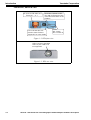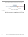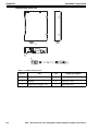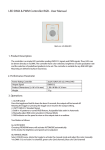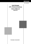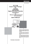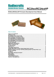
1
Heat Value Gas Chromatograph
Fieldbus Adapter Hardware Description
Model: HFA100
User’s Manual
CM2-HFA100-2001
First issue: Jan. 2003
Copyright, Notices and Trademarks
Printed in Japan - ©Copyright 2003 by Yamatake Corporation.
While this information is presented in good faith and believed to be
accurate, Yamatake Corporation disclaims the implied warranties of
merchantability and fitness for a particular purpose and makes no
express warranties except as may be stated in its written agreement
with and for its customer.
In no event is Yamatake Corporation liable to anyone for any indirect,
special or consequential damages. This information and specifications
in this document are subject to change without notice.
Copyright 2003 by Yamatake Corporation
All Rights Reserved
Table of Contents
Chapter 1 :Introduction
1-1 :Definition of term........................................................................................... 1-1
General ...................................................................................................... 1-1
Chapter 2 :Installation
2-1 :Connecting the fieldbus cable to the terminal block...................................... 2-1
2-2 : Connecting the USB and the terminal block to HFA .................................... 2-1
2-3 :Conforming operation ................................................................................... 2-2
Appendix.............................................................................A-1
List of Figure
Figure 1-1
Figure 1-2
Figure 1-3
Figure 2-1
Figure 2-2
Figure 2-3
HFA............................................................................................................................1-1
HFA front view ..........................................................................................................1-2
HFA rear view............................................................................................................1-2
Front view ..................................................................................................................2-1
Top view ....................................................................................................................2-1
Cable connections ......................................................................................................2-2
List of Table
Table 1-1
Table 2-1
Table A-1
Table A-2
Box Contents........................................................................................................ 1-1
Fieldbus cable description.................................................................................... 2-1
LAS LED ............................................................................................................. 2-1
Replacement parts list .......................................................................................... 2-2
Chapter 1 :
Introduction
1-1 : Definition of term
Heat Value Gas Chromatograph Fieldbus Adapter (HFA)
HFA is an interface used to connect the HGM (HGC monitor) , Windows-based PC
application, to Yamatake's state of the art analyzer, HGC (Heat value Gas Chromatograph) that operates on FOUNDATION™ fieldbus H1 network. Users are able to configure, monitor and maintain the HGC all from the PC by simply connecting the HFA to
the Fieldbus network.
1-2: General
Please confirm the following items are contained in the box.
Fieldbus adapter
Terminal block
Figure 1-1 HFA
Table 1-1 Box Contents
Name
Quantity
Fieldbus Adapter
1
USB Cable A-B type 1m
1
Terminal Block
1
Fieldbus Cable TypeA
1
CD-ROM
1
HFA100 - Heat Value Gas Chromatograph Fieldbus Adapter Hardware Description
1-1
Introduction
Yamatake Corporation
Connection, Switch & LED
FB: Connect FB cable here.
Terminal 1: -, 2: +
Terminator: Default is OFF.
Turn ON if HFA must be one
of the two terminators on the
Fieldbus.
LAS: Indicates the LAS
function status. Refer to
"Appendix" for more details.
Power
ON: Green
OFF: Turned off
Figure 1-2 HFA front view
USB: Connect to standard
USB 1.0 port. USB 2.0 is
not supported.
Figure 1-3 HFA rear view
1-2
HFA100 - Heat Value Gas Chromatograph Fieldbus Adapter Hardware Description
Chapter 2 :
Installation
To setup the Fieldbus connection, prepare a Fieldbus cable with following specifications:
Table 2-1 Fieldbus cable description
Type
Cable Description
Size
Maximum Length
A
Shielded, Twisted Pair
#18 AWG 0.8 mm2
1900 m (6232 ft)
Make sure the Terminator is switched to OFF.
2-1 : Connecting the fieldbus cable to the terminal block
(1) Detach the orange terminal block from the FB terminal of the HFA by unscrewing
the 2 screws located in front of the terminal block. See Figure 2-1.
Screws
Figure 2-1 Front view
(2) Loosen the 2 screws located on the top of the terminal block. See Figure 2-2.
Screws
Figure 2-2 Top view
(3) Connect the Fieldbus cable to the terminal block. Negative Fieldbus cable goes
into terminal '1' and the positive goes into terminal '2'
(4) Tighten the two screws on the top of terminal block to secure the connection.
Lightly pull on the cable to make sure the cable does not slip off
2-2 : Connecting the USB and the terminal block to HFA
Plug in the terminal block into the socket labeled 'FB'. Tighten the screws to secure the
terminal block. Then Connect the B-plug of the USB Cable to the USB connector of
HFA100 - Heat Value Gas Chromatograph Fieldbus Adapter Hardware Description
2-1
Installation
Yamatake Corporation
HFA. Next, connect the A-plug of the cable to the USB port of your computer. See
Figure 2-3 below.
USB cable
Terminal block
Figure 2-3 Cable connections
2-3 : Conforming operation
If your computer is not on at this point, turn it on. After connecting the USB cable,
make sure that the LED for POWER is ON, and LED for LAS is OFF. If not, check
your connections.
2-2
HFA100 - Heat Value Gas Chromatograph Fieldbus Adapter Hardware Description
Appendix
About Terminator Switch
In most cases, Terminator should be turned OFF. Turn it ON only if HFA must be one
of the two terminators on the Fieldbus.
About Link Active Schedule (LAS) LED
The table below summarizes the meaning LAS LED
Table A-1 LAS LED
LED Condition
Meaning
OFF
HFA is set as "Basic Device." LAS function is not available
ON
HFA is set as "Link Master Device." LAS function is available
and the function is active.
Blinking
HFA is set as "Link Master Device." LAS function is available
but the function is not active.
~Note
1. When HFA is powered up, it takes approximately 6~7 seconds to
complete initialization. The current status of LAS will be shown
on the LED after the completion of the initialization process.
2. When HFA is powered up, address value and HFA setup will be
initialized into their default values. Default address is FC, and
HFA will be set as "Basic device."
3. For HGM installation and operation, refer to HGC User's Manual (CM2-HG100-2001).
4. For HFA specifications, refer to HFA Specification Sheet (SS2HFA-100-0100).
HFA - Heat Value Gas Chromatograph Fieldbus Adapter Hardware Description
A-1
Appendix
Yamatake Corporation
Replacement Parts List
1
2
3
Table A-2 Replacement parts list
Key no.
A-2
Part
Qty.
Diaphragm number
1
Terminal block
1
80344399-001
2
Rubber
4
80340707-001
3
USB cable (length: 1 m)
1
80344409-001
HFA - Heat Value Gas Chromatograph Fieldbus Adapter Hardware Description
Document Number:
CM2-HFA100-2001
Document Name:
Heat Value Gas Chromatograph Fieldbus
Adapter Hardware Description
Model: HFA100
User’s Manual
Date:
Jan. 2003 (First issue)
Issued/Edited by:
Yamatake Corporation
Savemation
Totate international Building
2-12-19 Shibuya
Shibuya-ku, Tokyo 150-8316
Japan
Tel : 81-3-3486-2310
Fax : 81-3-3486-2593
Saving through Automation
http://www.yamatake.com/
This has been printed on recycled paper.