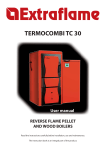
Download Manual Infrared camera PCE-TC 30
Transcript
PCE Americas Inc.
711 Commerce Way
Suite 8
Jupiter
FL-33458
USA
Tel: 410-387-7703
Fax: 410-387-7714
PCE Instruments UK Ltd.
Units 12/13
Southpoint Business Park
Ensign way
Southampton
Hampshire
United Kingdom, SO31 4RF
Tel: 02380 98703 0
Fax: 02380 98703 9
[email protected]
[email protected]
www.pce-instruments.com/us
www.pce-instruments.com/english
www.industrial-needs.com
Manual
Infrared camera PCE-TC 30
Version 1.0
Date of creation: 05/12/2014
Date of last change: 29.12.2014
Manual
Table of contents
1
Introduction ............................................................................................................. 3
2
Safety information ................................................................................................... 3
3
Specifications .......................................................................................................... 4
4
Device description .................................................................................................. 5
4.1
Camera components .................................................................................................................. 5
4.2
Buttons........................................................................................................................................ 5
4.3
Display ........................................................................................................................................ 5
5
Instructions.............................................................................................................. 6
5.1
5.1.1
5.1.2
To charge the battery ................................................................................................................. 6
To charge via the USB interface .................................................................................................... 6
To charge via a charger ................................................................................................................. 6
5.2
Data transfer ............................................................................................................................... 6
5.3
Reference numbers of the most common material emissivities ................................................. 6
5.4
Start-up procedure ...................................................................................................................... 7
5.5
Display ........................................................................................................................................ 7
5.6
To save images .......................................................................................................................... 7
5.7
5.7.1
5.7.2
5.7.3
5.7.4
5.7.5
5.7.6
Settings ....................................................................................................................................... 7
Main display ................................................................................................................................... 7
Temperature analysis..................................................................................................................... 7
Emissivity setting............................................................................................................................ 7
Palette ............................................................................................................................................ 8
Temperature setting ....................................................................................................................... 8
System setting................................................................................................................................ 8
5.8
Focussing ................................................................................................................................... 8
5.9
Colour scale ................................................................................................................................ 8
5.10
To display images ....................................................................................................................... 8
5.11
Switch-off .................................................................................................................................... 8
5.12
5.12.1
5.12.2
5.12.3
Software...................................................................................................................................... 9
Quick start of the software ............................................................................................................. 9
Hardware and software configuration ............................................................................................ 9
To operate the software ............................................................................................................... 10
6
Disposal ................................................................................................................. 24
7
Contact ................................................................................................................... 24
7.1
PCE Instruments UK ................................................................................................................ 24
7.2
PCE Americas .......................................................................................................................... 24
2
Manual
1
Introduction
Thank you for purchasing a PCE-TC30 infrared camera from PCE Instruments.
The PCE-TC 30 thermographic camera is perfect for beginners. Its structure is very simple, which makes
it very uncomplicated to use. Therefore, users need little time to get used to the device. Its favourable
price is one of the many advantages of this infrared camera.
The device is commonly used in construction, electrical installation and diagnostics, as well as production
and maintenance processes.
The fact that the camera has only very few buttons makes it easily possible to operate it with only one
hand.
2
Safety notes
Please read this manual carefully and completely before you use the device for the first time. The device
may only be used by qualified personnel and repaired by PCE Instruments personnel. There is no
warranty of damages or injuries caused by non-observance of the manual and particularly of the safety
information. In addition to the local rules at your workplace, the following safety notes must be observed
at any time.
- The device may only be used in approved temperature range. Do not make any measurements if the
ambient temperature is higher than the one stated in the specifications.
- Avoid exposure to extreme radiation, e. g. from sunlight, carbon dioxide lasers or arc welders.
- Protect the device from dust and water. If you work in an environment which is close to water, make
sure that the device is also protected from splashing water.
- The case must only be opened by qualified personnel of PCE Instruments. Otherwise, the warranty will
become void.
- The instrument should never be placed with the user interface facing an object (e.g. keyboard side on a
table).
- You should not make any technical changes to the device.
- The non-optical parts of the camera should be cleaned with a soft cloth which has been dipped into
water. The optical parts should only be cleaned if they are visibly dirty. Use a lens cleaning cloth.
- Always hold the camera tightly when using it.
- Whenever you do not wish to use the camera or want to transport it, ensure that it is in the carrying bag
designed for this purpose.
- Always make sure that the holes in the infrared camera are open and not blocked by any foreign
objects.
- Do not switch the camera back on within 15 seconds after switching it off.
- Do not expose the camera to impact, shock or strong vibration as this can cause damage to the camera
or parts of the camera.
- Only use the SD card with the infrared camera.
- Never attempt to disassemble or open the rechargeable battery and never expose it to fire or high
temperatures.
- Do not short-circuit the battery.
- Keep the battery away from water or moisture.
- For charging, only use the accessories you received along with this product.
- Do not touch the lens with your fingers.
This manual is published by PCE Instruments without any guarantee.
We expressly refer to our general guarantee terms, they can be found in our general terms of business.
If you have any questions please contact PCE Instruments.
3
Manual
3
Specifications
Resolution of sensor
Measurement range
Analysis functions
Display
Thermal sensitivity
80 x 80
0 ... +250 °C
specific point temperature measurement
temperature area measurement (Tmax / Tmin)
HOLD function (Tmax / Tmin)
LCD 320 x 240 pixels
80 mK
Lens
8 mm
Digital zoom
3x
Field of view (FOV)
18.5 x 18.5 "
Frequency
50 Hz
Working temperature
0 ... +50 °C
Interface
Measurement parameters
Power supply
micro USB
adjustable emissivity
replaceable battery
Battery life
approx. 4 hours
Dimensions
103 x 98 x 258 mm
Weight
755 g
Protection class
IP43
4
Manual
4
Device description
4.1
Camera components
4.3
Display
4.2
Buttons
5
Manual
5
Instructions
5.1
To charge the battery
When the device is in charging mode, the red LED next to the micro USB interface glows permanently. In
case the battery is not fixed properly or completely missing, the red LED will flash until it has been
inserted correctly. Please bear in mind that the battery must be locked at its bottom side by means of the
locking mechanism so that it cannot be removed and can be charged properly.
5.1.1 To charge via the USB interface
It is possible to charge the device via the USB interface. To do so, connect the USB cable to the USB port
and the other end of the cable to the USB charging adapter included in the delivery. Then connect the
charging adapter to a socket. When first using the appliance, it must have been charged for at least four
hours, until the red charging signal turns off.
5.1.2 To charge via a charger
There is also the possibility to charge the battery via a charger which is, however, not included in the
delivery and can be purchased separately.
5.2
Data transfer
You can easily transfer your measured data to a suitable computer. You can remove the SD card from
the camera and insert it into an appropriate card reader which is connected to the computer. This is an
easy way to transfer the images from the camera to the computer.
The second possibility is to connect the camera to a computer directly via USB. Then you can transfer the
images to images to the computer. Please note that the display freezes when the camera is connected to
a computer.
5.3
Reference numbers of the most common material emissivities
Material
Water
Stainless steel
Polished aluminium
Black aluminium
Asphalt
Black paper
Concrete
Cast iron
Plaster
Rubber
Wood
Brick
Rubber belt
Polished copper
Human skin
PVC
Polycarbonate
Oxidised copper
Rust
Paint
Soil
Emissivity
0.96
0.14
0.09
0.95
0.96
0.86
0.97
0.81
0.75
0.95
0.85
0.75
0.95
0.06
0.98
0.93
0.80
0.78
0.80
0.90
0.93
6
Manual
5.4
Start-up procedure
Before using the device for the first time, charge the battery sufficiently (for at least 4 hours). Insert the
battery correctly into the camera until you hear a clear clicking sound. Then connect the fuse to the
bottom side of the battery. Open the cap in front of the lens and put it on the top side of the camera. Due
to magnetism, the cap will not fall down during the measurement and interfere with it. After this, push the
power button on the right-hand side below the LC display for approx. 4 seconds. When the device is
completely switched on, you can start with your measurement.
5.5
Display
The display then shows the infrared image along with the colour palette on the right-hand side and the
adjustable emission rate in the upper left corner of the display. On the right next to the emission rate, the
temperature of the object pointed at by the hair cross in the middle of the display is indicated. On the
upper right-hand side, time and battery level are displayed.
5.6
To save images
By pushing the Trigger button on the front side of the infrared camera, the image shown on the display
can be saved on the SD card if an SD card is inserted. Make sure that the SD card is inserted if you want
to save your images. If this is not the case and the user still pushes the Trigger button, the display will
indicate “! No SD card”. If the images have been successfully saved on the SD card, the device will
indicate “Saving”.
5.7
Settings
You can make various settings to the device. To get to the menu, push the select left button directly under
the LCD. After this, the menu will open and you can decide what settings you wish to make by selecting
with the “+” and “-” buttons. By pushing the select button again, you can select the appropriate adjustment
range and use the sub-menus in the same way as the main menu. The following sub-menus are
available:
5.7.1 Main display
In this menu, the display only shows the image, the colour palette, the emissivity, the hair cross and the
battery level. If you want to make a measurement where the hair cross is located, you must pull the
trigger. The temperature measured at that point will also be indicated. This will remain on the LCD until a
new measurement is triggered. If you push the select left button again, the device will show all information
on the display again.
5.7.2 Temperature analysis
For temperature analysis, you can choose between different measurement functions. You can select the
functions “point” (standard), “range max.”, “range min.”, “over” and “below”. If you choose point
measurement, you measure the point shown by the hair cross. When you choose “range max.”, the
display will show a range in the form of a square. Inside the square, the hair cross will now appear and
jump to the warmest spot inside the square. The measurement function “range min.” works the same way
with the only difference that the hair cross will show the coldest spot in the image. The functions “over”
and “below” are set point measurements. The user can set the measurement value. If you have selected
the “over” function, the range above the chosen temperature is indicated in green. When you have
selected the “below” function, the opposite is the case. If the camera detects objects the temperature of
which is below the set value, these objects are indicated in red.
5.7.3 Emissivity setting
The emissivity is set by the user here. The most common materials are already pre-set. In case you wish
to set another emissivity, you must choose “user setting”. Here you can set an emissivity yourself.
7
Manual
5.7.4 Palette
Here the user can set the palette shown on the display during the measurement. Different palettes are
available for different purposes. You can navigate through the palettes by means of the arrow buttons.
5.7.5 Temperature setting
Here you can select the temperature unit, either °C or °F.
5.7.6 System setting
Via the system settings you can change or set various functions, for instance you can set automatic
switch-off or functions like date, time, language or brightness. You can also reset the device to factory
defaults. Furthermore, you can find a help function which makes it easier for the user to handle the
device.
5.8
Focussing
To get a high-resolution image, you can find a focusing wheel at the front side of the camera which is
used to adjust the resolution of the images in line with different distances.
5.9
Colour scale
The colour scale is on the right-hand side of the display and runs vertically. The colours of the scale
change in line with the palette used for the measurement. It gives an approximate outline of the
temperatures measured outside the hair cross. In relation to the ambient temperatures, the colour scale
can be very detailed. There are two different modes for this purpose: the “auto” mode and the “lock” mode
(factory default setting). If “lock” mode is on, the scale has fixed extremes. In “auto” mode, the limits are
variable and adapt to their environment.
5.10 To display images
To display the images, you must push the play button below the select left button so that the saved
images are shown on the display. You can then have a look at them again or delete them. If you push the
play button and the display shows the text “”! No SD card”, the SD card has been removed and must be
inserted again. In this case, the display will also show a symbol on the left side of the time indication
which looks like a stylised SD card along with an exclamation mark.
5.11 Switch-off
There are several possibilities to switch the device off. Firstly, it is possible to switch the device off for
only a short time to save battery power. To do so, you must only push and release the power button. To
unfreeze the display, you must push the power button again or pull the trigger.
To switch the device off completely and permanently, you must push and hold the power button. The
switch-off process is then indicated on the display. Hold the button until the indication “POWER OFF” is
complete and the device switches off as otherwise the process would be interrupted and the device would
remain switched on.
After switching the device off, the cover should be closed again to ensure protection of the lens.
8
Manual
5.12 Software
5.12.1 Installation of the software
Insert the SD card included in the delivery content into an SD card reader or directly into the SD card slot.
The automatic playback of your computer will then open. The software is on the SD card and can be
installed via “setup”.
5.12.2 Hardware and software configuration
5.12.2.1 Hardware configuration – minimum requirements
Requirement
CPU
RAM
Graphic card
Hard disc
Mouse and keyboard
Network adapter
Details
Pentium 4 2.4 GHz
512 MB and more
NVIDIA GeForce 5200 125 MB
40 GB and more
Mouse with 3 keys, PS/2 keypad
100 MB
5.12.2.2 Software configuration – minimum requirements
Requirement
Environment
Operating system
Other software
Details
.net framework 3.5 SP1
Microsoft Visual C++2010 x86
Windows Installer 3_1 report viewer
Windows XP 32/64 Bit
Adobe Reader
9
Manual
5.12.3 To operate the software
5.12.3.1 To open data
5.12.3.2 Picture analysis
5.12.3.2.1 Import of the data
To open the saved thermal images in the software, it is necessary to connect the camera to a computer
via USB. Your computer will then show an additional virtual drive called “GUIDE_IR”. The pictures taken
by the camera are saved under “DCIM” under “PICTURE”: You must then copy the data from that location
and save them in the folder “Guide Files”. You can find the folder “Guide Files” where you have saved the
device software on your computer. Start the software then. The pictures in the folder “Guide Files” are
automatically recognised by the software.
10
Manual
5.12.3.2.2 To create new folders
To create a new folder, click on the “+” in the directory on the left-hand side. Enter the folder name and
click on “confirm” to create the folder. You can create a subfolder under each folder.
5.12.3.2.3 To delete folders
Click to select the folder to be deleted… The symbols “+” and “-” appear next to the folder. When you
click on “-”, you start the deleting process. A window will then open and ask whether you really want to
delete the folder. By clicking n “confirm”, you delete the folder irrevocably.
11
Manual
5.12.3.2.4 Image properties
Select the thumbnail display in the software to get an overview of all important image properties on the
right-hand side, including the type of device and the size of the image.
5.12.3.2.5 Note on commented images
In case you see a
in connection with the
image properties, this means that there is a
comment along with the selected image.
If the selected image comes with a
, this
means that an audio recording has been added to
the image.
It is also possible that the symbol
is shown
in connection with an image. In this case,
information about the place where the image has
been taken has been added.
12
Manual
5.12.3.3 Picture analysis
5.12.3.3.1 To load an image
1. When all images are displayed, you must double-click on the picture you would like to select.
2. If an image has already been loaded, you can click on
to choose another one.
3. Select an image in normal mode and pull it to the analysis interface with the mouse. The
programme then recognises the image automatically and displays the corresponding image
information and properties.
13
Manual
5.12.3.3.2 To add analysis tools
You have the possibility to add analysis tools to the image by means of the software
To add spots:
Click on
. The spot will then be displayed like this:
To add lines:
Click on
. The line will then be displayed like this:
14
Manual
Dashed line:
Click on
. The dashed line will be displayed like this:
Rectangle:
Click on .
The rectangle will be displayed like this:
Circle:
Click on
. The circle will be displayed like this:
Polygon:
Click on
. The polygon will be displayed like this:
15
Manual
5.12.3.3.3 Three-dimensional display
When you click on
, the image is displayed three-dimensionally. This makes it possible for you to
turn it by means of the mouse. You can also increase or decrease the size of the image. This looks as
follows:
16
Manual
5.12.3.3.4 To set the colour palette and the display
You can choose between nine different colour palettes. To do so, click on
be shown and the palette can be changed.
. The colour palettes will
The slide controls in the software can be set individually to set the colour effect in the image as desired.
When you click on “Auto”, the default limits are restored.
Click on
to save the colour palette as you have set it.
5.12.3.3.5 Emissivity
You can choose a value from the analysis information which you have to double-click on. Then, a new
window will open in which the emissivity value of the measurement can be adjusted. This emissivity value
is adopted and saved after you have clicked on “confirm”.
If you would like to change the emissivity value of all analysis tools, you must double-click on the
emissivity value in the infrared settings and then change and save this value correspondingly.
17
Manual
5.12.3.4 Report creation
18
Manual
5.12.3.4.1 To load an image
When you double-click on an image on the left-hand side, the document will be automatically created.
The images taken before are also displayed as an infrared image as well as a normal image.
5.12.3.4.2 To add letters
The user can easily make changes to the template.
: adds texts fields to the template.
: adds a comment to the template.
: adds a highlight to the template.
NOTE: The inserted letters can be removed by pushing the “Del.” button when they are highlighted.
5.12.3.4.3 Page settings
Click on “Search” to choose an image as logo.
19
Manual
5.12.3.4.4 To insert templates
Click on
to open the template database. You can create a new template by clicking on
can delete it by clicking on
. The template currently used is highlighted in green:
5.12.3.4.5 To export reports
By clicking on “Export”, you can save reports as Word, Excel or PDF files.
20
. You
Manual
5.12.3.5 Settings
5.12.3.5.1 Language
You can choose between German, English. Polish, Spanish and Chinese as software language.
5.12.3.5.2 Units
The software offers the possibility to adjust temperature and length units in line with user needs and
purposes. As temperature units, you can choose between degrees Celsius, degrees Fahrenheit and
Kelvin. As length units, meters and inches are available.
21
Manual
5.12.3.5.3 Show
Here, you can set what is displayed in what way. You can select either both extremes, the maximum
temperature, the minimum, temperature or none.
5.12.3.5.4 Report
Here, you can make a standard setting of what is to be shown in the report. You can determine the
standard logo as well as header and footer.
22
Manual
5.12.3.5.5 Others
Further settings regarding updates and popup windows can be adjusted here.
23
Manual
6
Disposal
Due to the contained pollutants, batteries must not be disposed of as household waste. They must be
given to collection points designed for that purpose.
In order to comply with the ElektroG (German Electrical Equipment Act), we take our devices back. We
either re-use them or give them to a recycling company which disposes of the devices in line with law.
If you have any questions, please contact PCE Instruments.
All products are CE and RoHs approved.
7
Contact
If you have any questions about our range of products or measuring instruments please contact PCE
Instruments.
7.1
PCE Instruments UK
By post:
PCE Instruments UK Ltd.
Units 12/13 Southpoint Business Park
Ensign Way, Southampton
Hampshire
United Kingdom, SO31 4RF
By phone:
Support: 02380 987 035
Sales: 02380 987 030
7.2
PCE Americas
By post:
PCE Americas Inc.
711 Commerce Way
Suite 8
Jupiter
33458 FL
USA
By phone:
Phone: 410-387-7703
Fax: 410-387-7714
You can find an overview of our measuring instruments here: http://www.industrial-needs.com/measuring-instruments.htm
You can find an overview of our scales here http://www.industrial-needs.com/balances.htm
24


