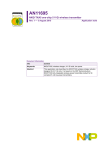
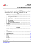
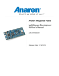
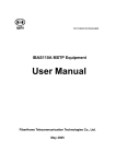
1
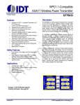
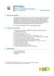
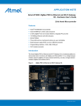
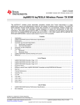
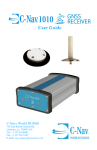
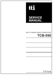
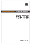
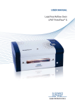
UM10917 NXQ1TXA5DB1340 one-chip 5 V Qi wireless transmitter demo board Rev. 1 — 3 August 2015 User manual Document information Info Content Keywords NXQ1TXA5DB1340, NXQ1TXA5, wireless charger, high efficiency, CoolFlux DSP, A5, A11 Qi Abstract This user manual describes the NXQ1TXA5DB1340 wireless power transmitter WPC1.1 demo board. It is designed for A11 Qi coils, based on the NXP Semiconductors NXQ1TXA5 fully integrated wireless power transmitter IC for Qi compliant 5 V low-power transmitters. The hardware is described and a brief description for operating the board is given. UM10917 NXP Semiconductors NXQ1TXA5DB1340 one-chip 5 V Qi wireless transmitter demo board Revision history Rev Date Description v.1 20150803 first issue Contact information For more information, please visit: http://www.nxp.com For sales office addresses, please send an email to: [email protected] UM10917 User manual All information provided in this document is subject to legal disclaimers. Rev. 1 — 3 August 2015 © NXP Semiconductors N.V. 2015. All rights reserved. 2 of 32 UM10917 NXP Semiconductors NXQ1TXA5DB1340 one-chip 5 V Qi wireless transmitter demo board 1. Introduction Fig 1. NXQ1TXA5DB1340 demo board This user manual describes the NXQ1TXA5DB1340 wireless power transmitter WPC1.1 demo board. The demo board is designed for A11 Qi coils, based on the NXP Semiconductors NXQ1TXA5 fully integrated wireless power transmitter IC for Qi compliant 5 V low-power transmitters. The NXQ1TXA5 comes in a 5 mm 5 mm HVQFN32 package. Necessary information is given for a quick start-up of the demo board (see Chapter 2 Setup and operation of the NXQ1TXA5DB1340 demo board). Additional general information about the NXQ1TXA5 IC can be found in the “One-chip 5 V Qi wireless transmitter” data sheet (Ref. 1). All relevant general application information can be found in the “NXQ1TXA5 one-chip 5 V Qi wireless transmitter” application note (Ref. 2). 1.1 NXQ1TXA5 features • Single-chip WPC 1.1.2 Qi-compliant device for A5/A11/A12/A16 5 V single-coil low-power transmitter • Operates from 5 V supply • Integrated high-efficiency full-bridge power stage with low EMI radiation meeting EN55022 radiated and conducted emission limits • • • • • • UM10917 User manual Very few external components required, minimizing cost and board space Extremely low-power receiver detection circuitry; standby power 10 mW (typical) Power stage fully protected against overcurrent and overtemperature Fully integrated accurate coil current measurement Demodulates and decodes communication packages from Qi-compliant receivers PID regulation for closed-loop power drive and control All information provided in this document is subject to legal disclaimers. Rev. 1 — 3 August 2015 © NXP Semiconductors N.V. 2015. All rights reserved. 3 of 32 UM10917 NXP Semiconductors NXQ1TXA5DB1340 one-chip 5 V Qi wireless transmitter demo board • • • • • • Internal 1.8 V digital supply generation LED (2) and buzzer outputs NTC input for external temperature check and protection On-chip thermal protection Small HVQFN 32-pin package (5 mm 5 mm) with a 0.5 mm pitch Foreign Object Detection (FOD) with automatic switching between version 1.1 and version 1.0 for legacy receiver support • FOD levels can be adjusted using external resistors to compensate for application differences to meet Qi certification requirements • Smart Power Limiting (SPL) function to adapt to power-limited 5 V supplies • Static Power Reduction (SPR) function to limit power consumption • Supports Near Field Communication (NFC) TAG applications with a delayed start-up 1.2 NXQ1TXA5DB1340 demo board features The NXQ1TXA5DB1340 demo board is designed in such a way that it is easy to operate the NXQ1TXA5 device for demonstration and development purposes. The demo board is a good starting point for a fully qualified NXQ1TXA5-based application that can be mass-produced. The demo board contains the following components and features: • • • • NXQ1TXA5 integrated wireless power transmitter IC A blue LED serving as power indicator A red and green LED serving as functional (user interface) indicators Resonant capacitors (NP0 type) which together with the Qi transmitter coil make up the LC tank • A female micro USB receptacle for powering the board with a standard USB charger with rating of 1500 mA or more • • • • A11 Qi transmitter coil Resistors for FOD calibration settings Resistors for LED mode settings Solder jumpers for Smart Power Limiting (SPL) and Static Power Reduction (SPR) settings • Optional Negative Temperature Coefficient (NTC) connections to measure the coil temperature • Optional buzzer connection • Optional communication interface (beyond the scope of this manual) UM10917 User manual All information provided in this document is subject to legal disclaimers. Rev. 1 — 3 August 2015 © NXP Semiconductors N.V. 2015. All rights reserved. 4 of 32 UM10917 NXP Semiconductors NXQ1TXA5DB1340 one-chip 5 V Qi wireless transmitter demo board 2. Setup and operation of the NXQ1TXA5DB1340 demo board 2.1 NXQ1TXA5DB1340 board overview Fig 2. NXQ1TXA5DB1340 demo board assembly - top side 2.2 Connectors The NXQ1TXA5DB1340 demo board incorporates an on-board female micro-USB receptacle. Via this connector 5 V is supplied to the board. A standard USB adapter (5 V, minimum 1.5 A) can be used to feed the board. Optionally, a 10-pole dual-in-line connector can be mounted in the X2 position. With this connector, it is possible to communicate with the NXQ1TXA5 IC via I2C. Because communication with the NXQ1TXA5 IC is outside the scope of this manual, no further details are given here. The two-wire connection X14 can be used to connect a buzzer. In that case, resistor R34 (1 k) must also be mounted. The voltage on the CONFIG pin (pin 12) defines the behavior of the buzzer (See Section 2.4 and “NXQ1TXA5 one-chip 5 V Qi wireless transmitter” application note (Ref. 2)). UM10917 User manual All information provided in this document is subject to legal disclaimers. Rev. 1 — 3 August 2015 © NXP Semiconductors N.V. 2015. All rights reserved. 5 of 32 UM10917 NXP Semiconductors NXQ1TXA5DB1340 one-chip 5 V Qi wireless transmitter demo board 2.3 Jumpers The NXQ1TXA5DB1340 demo board contains two mounting positions for very low-ohmic 0805-size jumpers in the 5 V supply section (R43 and R44). By default these jumpers are mounted. When the jumpers are removed, a common-mode choke must be mounted in the L3 position. The mounted common-mode choke offers the opportunity to suppress residual conducted EMI that originates from the NXQ1TXA5 operation. However, in most applications using the L3 common mode choke is not necessary. SPR and SPL can be configured with the solder jumpers in the R30, R31, R32 and R33 position. By default, R30 and R32 are open and R31 and R33 are closed (SPR1 and SPR2 pins both grounded). Consequently, on delivery the SPR function is disabled. Details about alternative options are given in the “NXQ1TXA5 one-chip 5 V Qi wireless transmitter” application note (Ref. 2). Table 1. SPL status and SPR level SPR1 SPR2 SPL status and SPR level 0 (ground) 0 (ground) SPL on; no SPR limiting 0 (ground) 1 (VDDP) SPL on; 500 mA 1 (VDDP) 0 (ground) SPL on; 1000 mA 1 (VDDP) 1 (VDDP) SPL off; no SPR limiting By default, the 0603-size jumper in position R15 sets the logic level on the NFC_FD_N pin (pin 6) high. By this setting there is no start-up delay that would allow NFC communication to finalize before power transfer begins. 2.4 Configuration and FOD settings To set the LED/buzzer mode configuration and the FOD parameters, four pairs of resistors are used: • The R5/R6 pair sets the voltage level on the CONFIG pin (pin 12). The voltage on this pin defines the operation mode of LEDs and the buzzer (see also Section 2.5). In the default configuration mode, "Two LED 1" is selected. Table 2 lists the modes that are available. Table 3 and Table 4 describe the behavior of the LEDs and the buzzer for each of these modes. • The R11/R12 pair sets the voltage on the FOD1 pin (pin 9). The voltage on the FOD1 pin sets the FOD threshold level. In the default configuration (R11 = 390 k; R12 = 68 k), the FOD threshold level is set to 0.5 W. Table 5 gives an overview of the selectable FOD1 voltage levels and the consequences for FOD behavior. • The R9/R10 pair sets the voltage on the FOD2 pin (pin 10). The voltage on the FOD2 pin sets the B-coefficient in FOD power loss estimation equation. For details, see the “One-chip 5 V Qi wireless transmitter” data sheet (Ref. 1) and the “NXQ1TXA5 one-chip 5 V Qi wireless transmitter” application note (Ref. 2). In the default configuration (R9 = 390 k; R10 = 82 k), the B-coefficient is set to 0.108. Table 6 gives an overview of the selectable FOD2 voltage levels and the consequences for FOD behavior. • The R7/R8 pair sets the voltage on the FOD3 pin (pin 11). The voltage on the FOD3 pin sets the C-coefficient in FOD power loss estimation equation. For details, see the “One-chip 5 V Qi wireless transmitter” data sheet (Ref. 1) and the “NXQ1TXA5 one-chip 5 V Qi wireless transmitter” application note (Ref. 2). In the default UM10917 User manual All information provided in this document is subject to legal disclaimers. Rev. 1 — 3 August 2015 © NXP Semiconductors N.V. 2015. All rights reserved. 6 of 32 UM10917 NXP Semiconductors NXQ1TXA5DB1340 one-chip 5 V Qi wireless transmitter demo board configuration (R7 = 390 k; R10 = OPEN), the C-coefficient is set to 0.012. Table 7 gives an overview of the selectable FOD3 voltage levels and the consequences for FOD behavior. Summary Upon delivery, FOD is enabled with the FOD threshold level set to 0.5 W, B = 0.108, and C = 0.012. Additional details concerning FOD (FOD1, FOD2 and FOD3) settings and calibration can be found in the “One-chip 5 V Qi wireless transmitter” data sheet (Ref. 1) and the “NXQ1TXA5 one-chip 5 V Qi wireless transmitter” application note (Ref. 2). Table 2. UM10917 User manual Mode selection Input voltage on pin CONFIG Mode name VCONFIG < 40 mV two LED 1 85 mV < VCONFIG < 165 mV two LED 2 210 mV < VCONFIG < 290 mV two LED 3 335 mV < VCONFIG < 415 mV two LED 4 460 mV < VCONFIG < 540 mV two LED 5 585 mV < VCONFIG < 665 mV two LED 6 710 mV < VCONFIG < 790 mV two LED 7 835 mV < VCONFIG < 915 mV two LED 8 960 mV < VCONFIG < 1040 mV one LED 1 & 2 1085 mV < VCONFIG < 1165 mV one LED 3 & 4 1210 mV < VCONFIG < 1290 mV one LED 5 & 6 VCONFIG > 1335 mV debug LED All information provided in this document is subject to legal disclaimers. Rev. 1 — 3 August 2015 © NXP Semiconductors N.V. 2015. All rights reserved. 7 of 32 xxxxxxxxxxxxxxxxxxxxx xxxxxxxxxxxxxxxxxxxxxxxxxx xxxxxxx x x x xxxxxxxxxxxxxxxxxxxxxxxxxxxxxx xxxxxxxxxxxxxxxxxxx xx xx xxxxx xxxxxxxxxxxxxxxxxxxxxxxxxxx xxxxxxxxxxxxxxxxxxx xxxxxx xxxxxxxxxxxxxxxxxxxxxxxxxxxxxxxxxxx xxxxxxxxxxxx x x xxxxxxxxxxxxxxxxxxxxx xxxxxxxxxxxxxxxxxxxxxxxxxxxxxx xxxxx xxxxxxxxxxxxxxxxxxxxxxxxxxxxxxxxxxxxxxxxxxxxxxxxxx xxxxxxxx xxxxxxxxxxxxxxxxxxxxxxxxx xxxxxxxxxxxxxxxxxxxx xxx LED modes LED Mode Digital_Ping - LED_G Charging - LED_G (Power_Transfer mode) Receiver Fault detected[2] [1] charged LED_R LED_G Two LED 1 blink for 100 ms every 4 seconds blink for 100 ms every 400 ms when object detected on: full power blink at 0.5 Hz: limited power (SPL, SPR or average current exceeds 2 A) off Two LED 2 off Two LED 3 blink for 100 ms every 4 seconds blink for 100 ms every 400 ms when device detected blink at 1 Hz off off off off Two LED 5 blink for 100 ms every 4 seconds blink for 100 ms every 400 ms when device detected off Two LED 6 off off Two LED 7 off blink at 0.5 Hz blink at 1 Hz blink at 1 Hz off blink at 2 Hz blink at 2 Hz off x blink at 2 Hz for TX/RX error; no blink on FOD off off x LED_G: off off x blink at 2 Hz for TX/RX error; no blink on FOD LED_R Two LED 8 reserved LED_G: blink for 100 ms every 4 seconds on: full power blink for 100 ms every 400 ms when device detected blink at 0.5 Hz: limited power (SPL, SPR or average current exceeds 2 A) LED_R blink for 100 ms every 4 seconds blink for 100 ms every 400 ms when device detected One LED 3 & 4[3] One LED 5 & 6[3] off off x LED_G: blink for 100 ms every 4 seconds blink at 0.5 Hz blink for 100 ms every 400 ms when device detected off on x blink at 2 Hz for TX/RX error; no blink on FOD LED_R on off x off [1] ‘charge complete’ or ‘charge status 100 %’ message received via RX (NXQ1TXA5 remains in Power_Transfer mode while ‘charge status 100 %’ is reported; it switches to Charged mode when a ‘charge complete’ message is received). [2] Receiver reports ‘internal fault’, ‘overtemperature’, ‘battery failure’, or ‘no response’. Transmitter reports OTP or FOD. If the receiver reports ‘overcurrent’, ‘overvoltage’, or ‘unknown’, the device restarts and goes back to ping state. [3] User can connect LED to either LED_R or LED_G; so the voltage on CONFIG could be used to enable two separate One LED modes. UM10917 8 of 32 © NXP Semiconductors N.V. 2015. All rights reserved. Debug LED reserved NXQ1TXA5DB1340 one-chip 5 V Qi wireless transmitter demo board Rev. 1 — 3 August 2015 All information provided in this document is subject to legal disclaimers. Two LED 4 off One LED 1 & 2[3] NXP Semiconductors UM10917 User manual Table 3. xxxxxxxxxxxxxxxxxxxxx xxxxxxxxxxxxxxxxxxxxxxxxxx xxxxxxx x x x xxxxxxxxxxxxxxxxxxxxxxxxxxxxxx xxxxxxxxxxxxxxxxxxx xx xx xxxxx xxxxxxxxxxxxxxxxxxxxxxxxxxx xxxxxxxxxxxxxxxxxxx xxxxxx xxxxxxxxxxxxxxxxxxxxxxxxxxxxxxxxxxx xxxxxxxxxxxx x x xxxxxxxxxxxxxxxxxxxxx xxxxxxxxxxxxxxxxxxxxxxxxxxxxxx xxxxx xxxxxxxxxxxxxxxxxxxxxxxxxxxxxxxxxxxxxxxxxxxxxxxxxx xxxxxxxx xxxxxxxxxxxxxxxxxxxxxxxxx xxxxxxxxxxxxxxxxxxxx xxx NXP Semiconductors UM10917 User manual Table 4. Buzzer modes LED mode Buzzer mode Receiver fully charged Error (FOD, OTP, RX); ASK time-out not an error Two LED 1 two short beeps on entering state off one short beep every 4 S while in state Two LED 2 two short beeps on entering state off one short beep every 4 S while in state Two LED 3 two short beeps on entering state 4 short beeps on entering state one short beep every 4 S while in state Two LED 4 two short beeps on entering state 4 short beeps on entering state one short beep every 4 S while in state Two LED 5 two short beeps on entering state off one short beep every 4 S while in state Two LED 6 two short beeps on entering state off one short beep every 4 S while in state Two LED 7 two short beeps on entering state 4 short beeps on entering state one short beep every 4 S while in state Two LED 8 two short beeps on entering state 4 short beeps on entering state one short beep every 4 S while in state One LED 1&2 two short beeps on entering state off one short beep every 4 S while in state One LED 3&4 two short beeps on entering state 4 short beeps on entering state one short beep every 4 S while in state One LED 5&6 two short beeps on entering state off one short beep every 4 S while in state Debug LED two short beeps on entering state 4 short beeps on entering state one short beep every 4 S while in state UM10917 9 of 32 © NXP Semiconductors N.V. 2015. All rights reserved. NXQ1TXA5DB1340 one-chip 5 V Qi wireless transmitter demo board Rev. 1 — 3 August 2015 All information provided in this document is subject to legal disclaimers. Start charging UM10917 NXP Semiconductors NXQ1TXA5DB1340 one-chip 5 V Qi wireless transmitter demo board Table 5. FOD threshold difference Input voltage on pin FOD1 FOD threshold level VFOD1 < 0.04 V no FOD 0.25 V < VFOD1 1.29 V VFOD1 (V) / 1.5 W[1] 1.335 V < VFOD1 VDDP (VDDP is maximum input level) 0.5 W (default value) [1] This equation assumes VDDP = 5 V. To compensate for changes in the supply voltage level, the results are automatically adjusted. Table 6. B-coefficient value set via FOD2 Input voltage on pin FOD2 FOD parameter B VFOD2 < 0.04 V default value for parameters B and C: B = 0.11 and C = 0.012 0.085 V < VFOD2 1.29 V 0.067 VFOD2 (V) + 0.05[1] 1.335 V < VFOD2 VDDP (VDDP is maximum input level) reserved [1] This equation assumes VDDP = 5 V. To compensate for changes in the supply voltage level, the results are automatically adjusted. Table 7. C-coefficient value set via FOD3 Input voltage on pin FOD3 FOD parameter C 0.210 V < VFOD3 < 0.290 V[1] 0.006 0.585 V < VFOD3 < 0.665 V[1] 0.008 0.960 V < VFOD3 < 1.040 V[1] 0.010 VFOD3 > 1.335 V (VDDP is maximum input level)[1] 0.012 other voltage levels reserved [1] This condition assumes VDDP = 5 V. To compensate for changes in the supply voltage level, the conditions are automatically adjusted. 2.5 Indicators The NXQ1TXA5DB1340 demo board incorporates 3 on-board LED indicators: • H1: Green LED; user interface information (see Table 3) • H2: Red LED; user interface information (see Table 3) • H3: Blue LED; Power-on status (ON when 5 V supply present) Optionally, a buzzer can be connected to X14. When the buzzer is connected, resistor R34 (1 k) must be mounted as well. Table 4 gives the behavior of the buzzer. When the NXQ1TXA5DB1340 demo board is powered on, the green and red LEDs blink alternately followed by both LEDs being turned on and turned off. After that sequence, the NXQ1TXA5 enters analog ping mode. It checks once every 400 ms if a device is placed on the charger. The green LED H1 blinks every 4 s (indicating a digital ping being performed). Once a Qi compliant receiver is put on top of the Qi transmitter coil and the NXQ1TXA5 detects the receiver, it starts wireless power transmission. The green LED H2 turns on permanently until the receiver is removed again. If the power supply capability is UM10917 User manual All information provided in this document is subject to legal disclaimers. Rev. 1 — 3 August 2015 © NXP Semiconductors N.V. 2015. All rights reserved. 10 of 32 UM10917 NXP Semiconductors NXQ1TXA5DB1340 one-chip 5 V Qi wireless transmitter demo board limited, the NXQ1TXA5 enters Smart Power Limiting mode. To avoid that the supply voltage drops below 4.2 V, SPL reduces the output power. The green LED H2 then blinks with 1 s intervals. When a fault is detected, the red LED H2 blinks once every 1 s. UM10917 User manual All information provided in this document is subject to legal disclaimers. Rev. 1 — 3 August 2015 © NXP Semiconductors N.V. 2015. All rights reserved. 11 of 32 UM10917 NXP Semiconductors NXQ1TXA5DB1340 one-chip 5 V Qi wireless transmitter demo board 3. Schematic 9 9 5 Nȍ QP 9 5 Nȍ QP 5 0ȍ QP 'QP %$:6 9 9 + + *5((1 5(' 9 5 Nȍ 5 Nȍ 9 5 Nȍ 5 Nȍ QP FORVHWR LQGXFWRU 5 Nȍ .3++6685&. /('B5 /('B* 1)&B)'B1 %8== 6&/ 6&/ 635 635 6 1)&B',6 6'$ 6 9 ' ,' *1' 6 Fig 3. & Q) 9 & ) 9 5 6 9''3 9''3 67%< 5 5 ȍ ȍ QP 5 5 ȍ ȍ QP 9 9 * QP N+] & Q) 9 & Q) 9 & Q) 9 *1'3 *1'3 *1'3 & Q) 9 ( ,1' LQGXFWRU ( ,1' *1'3 287 287 & Q) 9 287 5 & ȍ Q) 9 9 * N+] & S) 9 & Q) 9 & Q) 9 & ) 9 ȍ ' 9 5 /QP '/:%70,6*/ 287 ; /) 1;47;$ 5 ȍ 287 287 9''3 9''3 635 635 &'(& 635 635 & ) 9 9 *1'' 5 0ȍ ;7$/B,1 1)&B',6 K9 6&/ & Q) 9 QP 966 6'$ 6'$ 17& 5 ȍ &21),* 5 Nȍ QP 5 Nȍ )2' 5 Nȍ )2' 5 ȍ 1 ;QP 0 5 Nȍ QP FORVHWR 1;47;$ & Q) 9 5 Nȍ K9 7(67 .3++660*&. 5 ȍ 9 ;7$/B287 5 Nȍ QP %8==(5 9 )2' 9 1)&B',6 9 ; QP 'QP %$:6 .3++64%&'9 & ) 9 QP 5 Nȍ DDD ȍ NXQ1TXA5DB1340 demo board schematic diagram UM10917 User manual All information provided in this document is subject to legal disclaimers. Rev. 1 — 3 August 2015 © NXP Semiconductors N.V. 2015. All rights reserved. 12 of 32 UM10917 NXP Semiconductors NXQ1TXA5DB1340 one-chip 5 V Qi wireless transmitter demo board 4. Bill Of Materials (BOM) Table 8. NXQ1TXA5 bill of materials Reference Description and values Part number Manufacturer C1; C2 capacitor; 6.8 nF; 50 V; 0603 - - C3; C4 capacitor; 82 nF; 50 V; NP0; 1206 GRM31C5C1H823JA01L Murata C5; C6 capacitor; 100 nF; 50 V; NP0; 1206 CGA5L2C0G1H104J160AA TDK C7; C8 capacitor; 10 nF; 50 V; NP0; 0603 - - C9; C10 capacitor; 22 F; 10 V; X7R; 1206 GRM31CR61A226KE19L Murata C11 capacitor; 100 nF; 50 V; X7R; 0603 - - C12 capacitor; 2.2 pF; 50 V; 0603 - - C13 capacitor; 100 F; 6.3 V; X5R; 1206 GRM31CR60J107ME39L Murata C26 capacitor; 10 nF; 50 V; X7R; 0805 - - C27 capacitor; not mounted; 100 nF; 25 V; X7R; 0603 - - C28 capacitor; not mounted; 1 F; 25 V; X7R; 0805 - - D4 diode; array; not mounted; CA; SOT363 BAW56S NXP Semiconductors G1 crystal; XTAL; 32.768 kHz; SMT S3215 Yoketan Corporation G2 crystal; XTAL; not mounted; 32.768 kHz; SMT AB26TRQ-32.768kHz-T Abracon Corporation H1 LED (green); 0402 KPHHS-1005MGCK Allied Electronics H2 LED (red); 0402 KPHHS-1005SURCK Allied Electronics H3 LED (blue); 0402 KPHHS-1005QBC-D-V Allied Electronics L3 inductor; common-mode choke; not mounted DLW5BTM251SQ2L Murata N1 IC NXQ1TXA5 NXP Semiconductors R1; R2 resistor; 1 ; 0603 - - R3 resistor; not mounted; 215 k; 1 %; 0603 R4 thermistor; NTC; not mounted; 100 k; NXFT15WF104FA2B050 1 %; 4250 K Murata R5; R7; R9; R11 resistor; 390 k; 1 %; 0603 - - R6; R15 resistor; 0 ; 0805 - - R8 resistor; not mounted; 22 k; 1 %; 0805 - - R10 resistor; 82 k; 1 %; 0805 - - R12 resistor; 68 k; 1 %; 0805 - - R13 resistor; 820 ; 0603 - - R14 resistor; 1 k; 0603 - - R30; R32 resistor; not mounted; 0 - - R31; R33 resistor; 0 ; solder closed - - R34 resistor; not mounted; 1 k; 1 %; 0603 - - UM10917 User manual All information provided in this document is subject to legal disclaimers. Rev. 1 — 3 August 2015 © NXP Semiconductors N.V. 2015. All rights reserved. 13 of 32 UM10917 NXP Semiconductors NXQ1TXA5DB1340 one-chip 5 V Qi wireless transmitter demo board Table 8. NXQ1TXA5 bill of materials …continued Reference Description and values R35 thermistor; NTC; not mounted; 100 k; NCP18WF104J03RB 5 %; 4250 K Part number Manufacturer Murata R36 resistor; not mounted; 100 k; 1 %; 0603 - - R37 resistor; not mounted; 2 M; 1 %; 0603 - - R38 resistor; 1 M; 1 %; 0603 - - R42 resistor; 3.9 k; 1 %; 0603 - - R43; R44 resistor; true 0 ; 0805 5106 Keystone X1 connector; micro-USB PCB socket 10104111-0001LF FCI X2 receptacle; straight; not mounted; 2 5-way; 2.54 mm M20-7830546 Harwin X14 header; straight; not mounted; 1 2-way; 2.54 mm - Molex UM10917 User manual All information provided in this document is subject to legal disclaimers. Rev. 1 — 3 August 2015 © NXP Semiconductors N.V. 2015. All rights reserved. 14 of 32 UM10917 NXP Semiconductors NXQ1TXA5DB1340 one-chip 5 V Qi wireless transmitter demo board 5. PCB layout The layout of an NXQ1TXA5 wireless power transmitter application is critical from an electrical and a thermal point of view. The PCB layout of the NXQ1TXA5DB1340 demo board as well as the aspects that are essential for proper operation are briefly explained below. More detailed explanations are given in the “NXQ1TXA5 one-chip 5 V Qi wireless transmitter” application note (Ref. 2). a. Top copper Fig 4. b. Component silk screen c. Bottom copper NXQ1TXA5DB1340 demo board layout UM10917 User manual All information provided in this document is subject to legal disclaimers. Rev. 1 — 3 August 2015 © NXP Semiconductors N.V. 2015. All rights reserved. 15 of 32 UM10917 NXP Semiconductors NXQ1TXA5DB1340 one-chip 5 V Qi wireless transmitter demo board Fig 5. UM10917 User manual Top side with silk screen All information provided in this document is subject to legal disclaimers. Rev. 1 — 3 August 2015 © NXP Semiconductors N.V. 2015. All rights reserved. 16 of 32 UM10917 NXP Semiconductors NXQ1TXA5DB1340 one-chip 5 V Qi wireless transmitter demo board Fig 6. Top side with via pattern 5.1 Electrical layout aspects • To enhance electrical conduction, the top and the bottom copper layer have a thickness of 70 m (2 Oz.). • The bottom layer is a shielding GND plane. It has been made maximally uninterrupted. • Shielding (non-current conducting) GND planes in the top copper layer are stitched to the non-current conducting GND areas of the bottom layer GND plane. The stitching is done with vias on the edges of the planes. It can easily be recognized on the right-hand side of Figure 6. • To prevent unnecessary power loss, VDD power traces to pins 15 and 16 and to pins 25 and 26 are wide low-impedance/low-loss traces. • Decoupling capacitors C10 and C8 are placed very close to pins 15 and 16. They have a low-impedance connection to GND. The same applies to capacitors C9 and C7 which are very close to pins 25 and 26. In this way, the two supply loops (see Figure 5) are kept as small as possible. • Snubber circuit capacitor C1 and resistor R1 and capacitor C2 and resistor R2 are mounted close to the output pins (pins 17 and 18; pins 23 and 24). The GND connections of the snubber circuits are close to IC GNDP pins 19, 20, 21, and 22. In this way, the two snubber loops (see Figure 5) are kept as small as possible. • The output pins of the NXQ1TXA5 IC have very wide (low-impedance) traces to the LC-tank. UM10917 User manual All information provided in this document is subject to legal disclaimers. Rev. 1 — 3 August 2015 © NXP Semiconductors N.V. 2015. All rights reserved. 17 of 32 UM10917 NXP Semiconductors NXQ1TXA5DB1340 one-chip 5 V Qi wireless transmitter demo board • Decoupling capacitor C11 is placed very close to pin 28. It has a low-impedance connection to GND. • To prevent overtones, the length of the traces leading to the crystal in series with the C12 capacitor is approximately 1 cm. 5.2 Thermal layout aspects • The NXQ1TXA5 IC is placed more or less in the center of the PCB. In that way, the IC benefits most from its cooling circle. • To ensure good thermal conduction, the GND pins and the power conducting pins of the IC are attached to large copper areas. • Underneath the NXQ1TXA5 IC, a pattern of 16 copper-filled thermal vias (see Figure 6) conducts heat from the top side to the bottom side of the PCB. Figure 7 shows the footprint that was used for soldering. • Many thermal vias surround the NXQ1TXA5 IC. The IC is the dominant dissipating component. • The top and bottom layers of the PCB are covered with standard solder resist. Standard solder resist has a fairly good emissivity, which enhances thermal radiation. Uncovered and shiny areas on the PCB are kept to a minimum. UM10917 User manual All information provided in this document is subject to legal disclaimers. Rev. 1 — 3 August 2015 © NXP Semiconductors N.V. 2015. All rights reserved. 18 of 32 UM10917 NXP Semiconductors NXQ1TXA5DB1340 one-chip 5 V Qi wireless transmitter demo board )RRWSULQWLQIRUPDWLRQIRUUHIORZVROGHULQJRI+94)1SDFNDJH 1;47;$ +[ WHUPLQDO LQGH[DUHD *[ ' & *\ 63\ WRW VROGHUPDVN +\ VROGHUPDVN VROGHUPDVN 6/\ %\ 63[WRW $\ VHHGHWDLO; 6/[ %[ $[ VROGHUODQG VROGHUODQGSOXVVROGHUSDVWH VROGHUPDVN GHWDLO; VROGHUSDVWH FRSSHUFRQQHFWSOXVVROGHUPDVN RFFXSLHGDUHD 5HFRPPHQGHGVWHQFLOWKLFNQHVVPP 'LPHQVLRQVLQPP 3 $[ $\ %[ %\ & ' 6/[ 6/\ ,VVXHGDWH Fig 7. 63[WRW 63\WRW 63[ 63\ Q63[ Q63\ *[ *\ +[ +\ Q[TW[DBIU Application-specific reflow soldering footprint UM10917 User manual All information provided in this document is subject to legal disclaimers. Rev. 1 — 3 August 2015 © NXP Semiconductors N.V. 2015. All rights reserved. 19 of 32 UM10917 NXP Semiconductors NXQ1TXA5DB1340 one-chip 5 V Qi wireless transmitter demo board 6. Performance 6.1 Efficiency In the power transfer path from the USB receptacle input to the load/battery at the output of the Qi receiver, power is lost due to conversion and transfer mechanisms. Below in blue the typical efficiency of the NXQ1TXA5DB1340 demo board alone is shown. The typical efficiency of the demo board is the fraction of input power that the NXQ1TXA5 application manages to convert into magnetic energy for transfer to the Qi receiver. Typically, this efficiency level is approximately 87 %. However, the system efficiency is more important to the end user. The system efficiency concerns the efficiency of the whole power chain from the USB input receptacle up to the load/battery. The typical system efficiency is shown in the gray curve in Figure 8. Typically, the system efficiency is approximately 74 % when the transmitter and receiver coils are aligned properly. DDD Ș 3R: (1) TX efficiency (RX_Pin/TX_Pin) (2) RX efficiency (RX_Pout/RX_Pin) (3) System efficiency (RX_Pout/TX_Pin) Fig 8. NXQ1TXA5DB1340 efficiency plots Figure 9 shows the system efficiency plot for a Samsung Galaxy S5 back cover Qi receiver (Ref. 3) with the NXQ1TXA5DB1340 demo board. For this combination, the system efficiency is also approximately 74 % (typical). UM10917 User manual All information provided in this document is subject to legal disclaimers. Rev. 1 — 3 August 2015 © NXP Semiconductors N.V. 2015. All rights reserved. 20 of 32 UM10917 NXP Semiconductors NXQ1TXA5DB1340 one-chip 5 V Qi wireless transmitter demo board DDD Ș Fig 9. 3R: System efficiency for the combination of the NXQ1TXA5DB1340 demo board and a Samsung Galaxy S5 back cover Qi receiver 6.2 Thermal performance When operating under maximum load conditions (5 W transferred to the load/battery on the Qi receiver side), the maximum temperature on the NXQ1TXA5DB1340 demo board is an important performance parameter. Figure 10 shows a thermal image (FLIR infrared thermal imaging camera) of the NXQ1TXA5DB1340 demo board under maximum load conditions and optimal alignment between the transmitter and the receiver coil. The Samsung Galaxy S5 back cover Qi receiver was used as the receiver. The maximum temperature difference (between the ambient and the hottest spot on the board) was 21.2 C. If the transmitter coil and the receiver coil are misaligned approximately 1 cm and the delivered power is still 5 W, the maximum temperature difference increases to 43.0 C. UM10917 User manual All information provided in this document is subject to legal disclaimers. Rev. 1 — 3 August 2015 © NXP Semiconductors N.V. 2015. All rights reserved. 21 of 32 UM10917 NXP Semiconductors NXQ1TXA5DB1340 one-chip 5 V Qi wireless transmitter demo board Fig 10. Thermal image at 5 W delivered power and optimal alignment Fig 11. Thermal image at 5 W delivered power and approximately 1 cm misalignment UM10917 User manual All information provided in this document is subject to legal disclaimers. Rev. 1 — 3 August 2015 © NXP Semiconductors N.V. 2015. All rights reserved. 22 of 32 UM10917 NXP Semiconductors NXQ1TXA5DB1340 one-chip 5 V Qi wireless transmitter demo board 6.3 EMI performance The NXQ1TXA5DB1340 demo board meets the CISPR22 (EN55022) requirements for both conducted and radiated emissions. All measurements were done at 5 W delivered to a load connected to the Samsung Galaxy S5 back cover Qi receiver under optimal alignment conditions. Figure 12 shows the conducted EMI spectrum for the NXQ1TXA5DB1340 demo board only. The 5 V supply to the board was from an EMI free linear power supply. Both the peak and the average emissions have over 30 dB margin compared to the limits. Figure 13 shows the radiated EMI under the same conditions. For radiated EMI, the margin compared to the limit is typically 20 dB and at no frequency less than 10 dB. Fig 12. Conducted EMI for the NXQ1TXA5DB1340 demo board only Fig 13. Radiated EMI for the NXQ1TXA5DB1340 demo board only EMI performance was also measured in combination with two regular 5 V USB adapters: • Samsung EP-TA10 • Nokia AC-60E UM10917 User manual All information provided in this document is subject to legal disclaimers. Rev. 1 — 3 August 2015 © NXP Semiconductors N.V. 2015. All rights reserved. 23 of 32 UM10917 NXP Semiconductors NXQ1TXA5DB1340 one-chip 5 V Qi wireless transmitter demo board Figure 14 shows the conducted EMI spectrum for the NXQ1TXA5DB1340 demo board in combination with the Samsung EP-TA10 USB adapter. Both peak and average emission have typically around 20 dB margin compared to the limits. At no frequency, the margin is less than 10 dB. Figure 15 shows the radiated EMI under the same conditions. For radiated EMI, the margin compared to the limit is typically in the range of 15 dB to 20 dB. At no frequency, it is less than 8 dB. Fig 14. Conducted EMI for the NXQ1TXA5DB1340 board with the Samsung EP-TA10 Fig 15. Radiated EMI for the NXQ1TXA5DB1340 board with the Samsung EP-TA10 Figure 16 shows the conducted EMI spectrum for the NXQ1TXA5DB1340 demo board in combination with the Nokia AC-60E USB adapter. The peak and the average emissions typically have an approximately 15 dB margin compared to the limits. At no frequency, the margin is less than 10 dB. Figure 17 shows the radiated EMI under the same conditions. For radiated EMI, the margin compared to the limit is typically in the range of 15 dB to 20 dB. At no frequency, it is less than 10 dB. UM10917 User manual All information provided in this document is subject to legal disclaimers. Rev. 1 — 3 August 2015 © NXP Semiconductors N.V. 2015. All rights reserved. 24 of 32 UM10917 NXP Semiconductors NXQ1TXA5DB1340 one-chip 5 V Qi wireless transmitter demo board Fig 16. Conducted EMI for the NXQ1TXA5DB1340 board with the Nokia AC-60E Fig 17. Radiated EMI for the NXQ1TXA5DB1340 board with the Nokia AC-60E The NXQ1TXA5DB1340 demo board mainly contributes to the radiated EMI spectrum of above 100 MHz. Most of the other noise can usually be attributed to the USB adapter. UM10917 User manual All information provided in this document is subject to legal disclaimers. Rev. 1 — 3 August 2015 © NXP Semiconductors N.V. 2015. All rights reserved. 25 of 32 UM10917 NXP Semiconductors NXQ1TXA5DB1340 one-chip 5 V Qi wireless transmitter demo board 7. NXQ1TXA5DB1340 demo board options and modifications Various alternative circuit options exist that can be realized on the NXQ1TXA5DB1340 demo board. 7.1 Smart Power Limiting (SPL) and Smart Power Reduction (SPR) Alternative Smart Power Limiting and Smart Power Reduction levels can be set with the jumpers in the R30, R31, R32 and R33 position. Details about the settings are given in Table 1 and in the “NXQ1TXA5 one-chip 5 V Qi wireless transmitter” application note (Ref. 2). Never install the (solder) jumpers in position R30 and R31 or the jumpers in position R32 and R33 simultaneously. 7.2 NFC The NXQ1TXA5 can also be used with an NFC (reader) enabled receiver. When the NFC_FD_N pin is LOW, a start-up delay of about 2 s is inserted when an NFC enabled receiver is placed on the charger. This delay allows the NFC enabled receiver to finalize communication with an NFC TAG before charging begins. The NXQ1TXA5 starts up after this delay. When it has detected a WPC-compliant Qi receiver, it starts to charge this device and disables the NFC functionality in the NFC reader via the NFC_DIS pin. If this feature is required, the jumper in position R15 must be removed and pin 6 of the IC must be connected to GND. 7.3 LEDs and buzzer By default, the user interface is built with 3 LEDs: • The blue LED indicates the power status • The green LED gives information about the operational status of the NXQ1TXA5DB1340 demo board • The red LED informs the user about faults that occur 7.3.1 Blue LED The blue power status LED can be eliminated when no presentation of the power status information is required. When the blue LED is eliminated, R42 can be eliminated as well. Adapting the R42 resistor value can change the brightness level of the blue LED. Do not select a value below 150 because the dissipation level in the blue LED can become too high. 7.3.2 Green LED The green LED can be eliminated when no information about the operational status is required. When the green LED is eliminated, R14 can be eliminated as well. The green LED can be set to behave differently by selecting another mode on the CONFIG pin (pin 12) of the NXQ1TXA5 IC. A specific mode is selected by presenting a specific voltage level (VCONFIG) to pin 12. UM10917 User manual All information provided in this document is subject to legal disclaimers. Rev. 1 — 3 August 2015 © NXP Semiconductors N.V. 2015. All rights reserved. 26 of 32 UM10917 NXP Semiconductors NXQ1TXA5DB1340 one-chip 5 V Qi wireless transmitter demo board Table 2 gives an overview of the available modes and related voltage levels (VCONFIG). Table 3 gives an overview of the way the green LED behaves for a specific mode. Set a specific mode by selecting a different resistance value for resistor R6. R6 V CONFIG = -------------------- 5.0 R5 + R6 (1) Adapting the R14 resistor value can change the brightness level of the green LED. Do not select a value below 150 because the dissipation level in the green LED can become too high. 7.3.3 Red LED The red LED can be eliminated when no information about fault conditions is required or when the fault condition information is combined with operational information. The latter is implemented through selecting one of the One LED x & y modes listed in Table 2. When the red LED is eliminated, R13 can be eliminated as well. The way the red LED behaves is selected through the CONFIG pin (pin 12; see Table 3). Adapting the R13 resistor value can change the brightness level of the red LED. Do not select a value below 150 because the dissipation level in the red LED can become too high. 7.3.4 Buzzer If, in addition to visual information, audial information is required, a buzzer can be connected to the X14 connector. If a buzzer is connected, resistor R34 must be mounted as well. Table 4 gives an overview of how the buzzer behaves when a certain mode is selected through the CONFIG pin. 7.4 FOD The NXQ1TXA5DB1340 demo board is delivered with the FOD threshold level set to 0.5 W (with VFOD1), the B-coefficient set to 0.108 (with VFOD2), and the C-coefficient set to 0.012 (with VFOD3). By applying other voltage levels to pins FOD1 (pin 9), FOD2 (pin 10), and FOD3 (pin 11), other settings can be realized. See Table 5 to Table 7 and the “NXQ1TXA5 one-chip 5 V Qi wireless transmitter” application note (Ref. 2). If no FOD is required, pin FOD1 can be connected to GND. Consequently, pins FOD2 and FOD3 can be grounded as well. Resistors R5, R6, R7, R8, R9, and R10 can be eliminated. If no flexibility in setting the threshold level is required and the 0.5 W level is appropriate, pin FOD1 can be connected to VDDP. So, resistors R11 and R12 can be eliminated. When the coefficients B = 0.11 and C = 0.012 are appropriate, pin FOD2 can be connected to GND and pin FOD3 to VDDP. Resistors R5, R6, R7 and R8 can be eliminated. In this way, two 'standard' configurations (No FOD and default FOD) can be implemented without using configuration resistors. UM10917 User manual All information provided in this document is subject to legal disclaimers. Rev. 1 — 3 August 2015 © NXP Semiconductors N.V. 2015. All rights reserved. 27 of 32 UM10917 NXP Semiconductors NXQ1TXA5DB1340 one-chip 5 V Qi wireless transmitter demo board 7.5 NTC One or two temperature sensors can be used on the NXQ1TXA5DB1340 demo board. One sensor is intended to measure the temperature on the NXQ1TXA5DB1340 board close to the NXQ1TXA5 IC. The other sensor is intended to measure the temperature of the transmitter coil. 7.5.1 Monitoring NXQ1TXA5 temperature If monitoring the NXQ1TXA5 IC temperature is required and if the application must react to that temperature accordingly, an SMT thermistor must to be mounted in the R35 position. Additionally, R36 and C27 must be mounted as well. Resistor R38 must be eliminated from the board. Finally, all 6 contacts of the D4 diode array must be shorted with a drop of solder. The values of resistor R36 and thermistor R35 determine the trip and resume temperature levels. For details and instructions regarding the calculation, see the “NXQ1TXA5 one-chip 5 V Qi wireless transmitter” application note (Ref. 2). 1 T trip = ----------------------------------------------------------------------------1 1 4 R36 ---------------- + --- ln ------ + ln ---------- R35 298.15 21 1 T res = ----------------------------------------------------------------------------1 1 11 R36 ---------------- + --- ln ------ + ln ---------- R35 298.15 39 (2) (3) Example: • R36 = 100 k • R35 = 100 k (at 25 C) • = 4250 K The trip temperature (Ttrip) is 64 C and the resume temperature (Tres) is 54 C. For more information, see the “NXQ1TXA5 one-chip 5 V Qi wireless transmitter” application note (Ref. 2) 7.5.2 Monitoring transmitter coil temperature If monitoring the transmitter coil temperature is required and if the application must react to that temperature accordingly, a wired thermistor must to be connected to the R4 wire holes (physically located between the transmitter coil soldering islands). Additionally, R3 and C27 must be mounted. Resistor R38 must be eliminated from the board. Finally, all 6 contacts of the D4 diode array must be shorted with a drop of solder. The values of resistor R3 and thermistor R4 determine the trip and resume temperature levels. For details and instructions regarding the calculation, see the “NXQ1TXA5 one-chip 5 V Qi wireless transmitter” application note (Ref. 2). 1 T trip = -------------------------------------------------------------------------1 1 4 R3 ---------------- + --- ln ------ + ln ------- R4 298.15 21 UM10917 User manual All information provided in this document is subject to legal disclaimers. Rev. 1 — 3 August 2015 (4) © NXP Semiconductors N.V. 2015. All rights reserved. 28 of 32 UM10917 NXP Semiconductors NXQ1TXA5DB1340 one-chip 5 V Qi wireless transmitter demo board 1 T res = -------------------------------------------------------------------------1 1 11 R3 ---------------- + --- ln ------ + ln ------- R4 298.15 39 (5) Example: • R3 = 215 k • R4 = 100 k (at 25 C) • = 4250 K The trip temperature (Ttrip) is 45 C and the resume temperature (Tres) is 36 C. 7.5.3 Monitoring the NXQ1TXA5 and transmitter coil temperature If monitoring both the NXQ1TXA5 IC and the transmitter coil temperature is required and if the application must react to these temperatures accordingly, an SMT thermistor must to be mounted in position R35. A wired thermistor must be connected to the R4 wire holes. Resistors R3, R36, R37, and capacitor C27 must be mounted as well. Finally, the D4 diode array must be mounted. The diode array operates as an "OR-ing" circuit for the two monitored temperatures. The values of resistor R36 and thermistor R35 determine the trip and resume temperature levels for the NXQ1TXA5 IC temperature. The values of resistor R3 and thermistor R4 determine the trip and resume temperature levels for the coil temperature. For details and instructions regarding the calculation, see the “NXQ1TXA5 one-chip 5 V Qi wireless transmitter” application note (Ref. 2). UM10917 User manual All information provided in this document is subject to legal disclaimers. Rev. 1 — 3 August 2015 © NXP Semiconductors N.V. 2015. All rights reserved. 29 of 32 UM10917 NXP Semiconductors NXQ1TXA5DB1340 one-chip 5 V Qi wireless transmitter demo board 8. Abbreviations Table 9. Abbreviations Acronym Description EMI ElectroMagnetic Interference FOD Foreign Object Detection LED Light-Emitting Diode NFC Near Field Communication NTC Negative Temperature Coefficient SPL Smart Power Limiting SPR Static Power Reduction WPC Wireless Power Consortium 9. References UM10917 User manual [1] One-chip 5 V Qi wireless transmitter — Data sheet, NXP Semiconductors, 2015 [2] NXQ1TXA5 one-chip 5 V Qi wireless transmitter — Application note, NXP Semiconductors, 2015 [3] Samsung Wireless charging cover — Model EP-CG900IBE All information provided in this document is subject to legal disclaimers. Rev. 1 — 3 August 2015 © NXP Semiconductors N.V. 2015. All rights reserved. 30 of 32 UM10917 NXP Semiconductors NXQ1TXA5DB1340 one-chip 5 V Qi wireless transmitter demo board 10. Legal information 10.1 Definitions Draft — The document is a draft version only. The content is still under internal review and subject to formal approval, which may result in modifications or additions. NXP Semiconductors does not give any representations or warranties as to the accuracy or completeness of information included herein and shall have no liability for the consequences of use of such information. 10.2 Disclaimers Limited warranty and liability — Information in this document is believed to be accurate and reliable. However, NXP Semiconductors does not give any representations or warranties, expressed or implied, as to the accuracy or completeness of such information and shall have no liability for the consequences of use of such information. NXP Semiconductors takes no responsibility for the content in this document if provided by an information source outside of NXP Semiconductors. In no event shall NXP Semiconductors be liable for any indirect, incidental, punitive, special or consequential damages (including - without limitation - lost profits, lost savings, business interruption, costs related to the removal or replacement of any products or rework charges) whether or not such damages are based on tort (including negligence), warranty, breach of contract or any other legal theory. Notwithstanding any damages that customer might incur for any reason whatsoever, NXP Semiconductors’ aggregate and cumulative liability towards customer for the products described herein shall be limited in accordance with the Terms and conditions of commercial sale of NXP Semiconductors. Right to make changes — NXP Semiconductors reserves the right to make changes to information published in this document, including without limitation specifications and product descriptions, at any time and without notice. This document supersedes and replaces all information supplied prior to the publication hereof. Suitability for use — NXP Semiconductors products are not designed, authorized or warranted to be suitable for use in life support, life-critical or safety-critical systems or equipment, nor in applications where failure or malfunction of an NXP Semiconductors product can reasonably be expected to result in personal injury, death or severe property or environmental damage. NXP Semiconductors and its suppliers accept no liability for inclusion and/or use of NXP Semiconductors products in such equipment or applications and therefore such inclusion and/or use is at the customer’s own risk. design. It is customer’s sole responsibility to determine whether the NXP Semiconductors product is suitable and fit for the customer’s applications and products planned, as well as for the planned application and use of customer’s third party customer(s). Customers should provide appropriate design and operating safeguards to minimize the risks associated with their applications and products. NXP Semiconductors does not accept any liability related to any default, damage, costs or problem which is based on any weakness or default in the customer’s applications or products, or the application or use by customer’s third party customer(s). Customer is responsible for doing all necessary testing for the customer’s applications and products using NXP Semiconductors products in order to avoid a default of the applications and the products or of the application or use by customer’s third party customer(s). NXP does not accept any liability in this respect. Export control — This document as well as the item(s) described herein may be subject to export control regulations. Export might require a prior authorization from competent authorities. Evaluation products — This product is provided on an “as is” and “with all faults” basis for evaluation purposes only. NXP Semiconductors, its affiliates and their suppliers expressly disclaim all warranties, whether express, implied or statutory, including but not limited to the implied warranties of non-infringement, merchantability and fitness for a particular purpose. The entire risk as to the quality, or arising out of the use or performance, of this product remains with customer. In no event shall NXP Semiconductors, its affiliates or their suppliers be liable to customer for any special, indirect, consequential, punitive or incidental damages (including without limitation damages for loss of business, business interruption, loss of use, loss of data or information, and the like) arising out the use of or inability to use the product, whether or not based on tort (including negligence), strict liability, breach of contract, breach of warranty or any other theory, even if advised of the possibility of such damages. Notwithstanding any damages that customer might incur for any reason whatsoever (including without limitation, all damages referenced above and all direct or general damages), the entire liability of NXP Semiconductors, its affiliates and their suppliers and customer’s exclusive remedy for all of the foregoing shall be limited to actual damages incurred by customer based on reasonable reliance up to the greater of the amount actually paid by customer for the product or five dollars (US$5.00). The foregoing limitations, exclusions and disclaimers shall apply to the maximum extent permitted by applicable law, even if any remedy fails of its essential purpose. Translations — A non-English (translated) version of a document is for reference only. The English version shall prevail in case of any discrepancy between the translated and English versions. Applications — Applications that are described herein for any of these products are for illustrative purposes only. NXP Semiconductors makes no representation or warranty that such applications will be suitable for the specified use without further testing or modification. 10.3 Trademarks Customers are responsible for the design and operation of their applications and products using NXP Semiconductors products, and NXP Semiconductors accepts no liability for any assistance with applications or customer product GreenChip — is a trademark of NXP Semiconductors N.V. UM10917 User manual Notice: All referenced brands, product names, service names and trademarks are the property of their respective owners. All information provided in this document is subject to legal disclaimers. Rev. 1 — 3 August 2015 © NXP Semiconductors N.V. 2015. All rights reserved. 31 of 32 UM10917 NXP Semiconductors NXQ1TXA5DB1340 one-chip 5 V Qi wireless transmitter demo board 11. Contents 1 1.1 1.2 2 2.1 2.2 2.3 2.4 2.5 3 4 5 5.1 5.2 6 6.1 6.2 6.3 7 7.1 7.2 7.3 7.3.1 7.3.2 7.3.3 7.3.4 7.4 7.5 7.5.1 7.5.2 7.5.3 8 9 10 10.1 10.2 10.3 11 Introduction . . . . . . . . . . . . . . . . . . . . . . . . . . . . 3 NXQ1TXA5 features . . . . . . . . . . . . . . . . . . . . . 3 NXQ1TXA5DB1340 demo board features . . . . 4 Setup and operation of the NXQ1TXA5DB1340 demo board . . . . . . . . . . . . . . . . . . . . . . . . . . . . 5 NXQ1TXA5DB1340 board overview. . . . . . . . . 5 Connectors . . . . . . . . . . . . . . . . . . . . . . . . . . . . 5 Jumpers . . . . . . . . . . . . . . . . . . . . . . . . . . . . . . 6 Configuration and FOD settings . . . . . . . . . . . . 6 Indicators . . . . . . . . . . . . . . . . . . . . . . . . . . . . 10 Schematic . . . . . . . . . . . . . . . . . . . . . . . . . . . . . 12 Bill Of Materials (BOM) . . . . . . . . . . . . . . . . . . 13 PCB layout . . . . . . . . . . . . . . . . . . . . . . . . . . . . 15 Electrical layout aspects . . . . . . . . . . . . . . . . . 17 Thermal layout aspects. . . . . . . . . . . . . . . . . . 18 Performance . . . . . . . . . . . . . . . . . . . . . . . . . . . 20 Efficiency . . . . . . . . . . . . . . . . . . . . . . . . . . . . 20 Thermal performance . . . . . . . . . . . . . . . . . . . 21 EMI performance . . . . . . . . . . . . . . . . . . . . . . 23 NXQ1TXA5DB1340 demo board options and modifications . . . . . . . . . . . . . . . . . . . . . . . . . . 26 Smart Power Limiting (SPL) and Smart Power Reduction (SPR) . . . . . . . . . . . . . . . . . 26 NFC . . . . . . . . . . . . . . . . . . . . . . . . . . . . . . . . 26 LEDs and buzzer . . . . . . . . . . . . . . . . . . . . . . 26 Blue LED . . . . . . . . . . . . . . . . . . . . . . . . . . . . 26 Green LED . . . . . . . . . . . . . . . . . . . . . . . . . . . 26 Red LED . . . . . . . . . . . . . . . . . . . . . . . . . . . . . 27 Buzzer . . . . . . . . . . . . . . . . . . . . . . . . . . . . . . 27 FOD . . . . . . . . . . . . . . . . . . . . . . . . . . . . . . . . 27 NTC . . . . . . . . . . . . . . . . . . . . . . . . . . . . . . . . 28 Monitoring NXQ1TXA5 temperature. . . . . . . . 28 Monitoring transmitter coil temperature . . . . . 28 Monitoring the NXQ1TXA5 and transmitter coil temperature . . . . . . . . . . . . . . . . . . . . . . . 29 Abbreviations . . . . . . . . . . . . . . . . . . . . . . . . . . 30 References . . . . . . . . . . . . . . . . . . . . . . . . . . . . 30 Legal information. . . . . . . . . . . . . . . . . . . . . . . 31 Definitions . . . . . . . . . . . . . . . . . . . . . . . . . . . . 31 Disclaimers . . . . . . . . . . . . . . . . . . . . . . . . . . . 31 Trademarks. . . . . . . . . . . . . . . . . . . . . . . . . . . 31 Contents . . . . . . . . . . . . . . . . . . . . . . . . . . . . . . 32 Please be aware that important notices concerning this document and the product(s) described herein, have been included in section ‘Legal information’. © NXP Semiconductors N.V. 2015. All rights reserved. For more information, please visit: http://www.nxp.com For sales office addresses, please send an email to: [email protected] Date of release: 3 August 2015 Document identifier: UM10917