1
CANCELLI AUTOMATICI
INTRODUCTION
TCA series
RBM8 SYSTEM
INDEX
topics
page
What is CameTCA RBM8? ........................................................................................ 2
Where to apply the CameTCA RBM8 ....................................................................... 3
What the CameTCA RBM8 can do ........................................................................... 4
RBM8 - INTRODUCTION
CANCELLI AUTOMATICI
RBM8 - INSTALLATION MANUAL
-§
1.1
What is CameTCA RBM8?
RBM8 is an integrated access-control system totally managed from a Personal Computer
The basic configuration is made up of two items of equipment: the RBM8 and PC30, and of a
proprietary software which is simply installed and easy to use on any computer with the Windows
Disk Operating System.
The RBM8 board is the heart of the system, and can be installed at a distance from the computer
(max. 1000 m) in that all the work of functions programming/modification/control, is managed by the
software.
The PC30 instead must be installed close to the computer (max 5 m) because it is the essential tool
for programming the code-command devices. The PC30 dialog indeed brings together all the
decodings necessary for save the CAME-compatible command devices:
- radio-controls series ATOMO, TAM and TOP;
- keyboards S5000, S6000 and S7000;
- Transponder-card readers TSP00 (proximity) and Magnetic cards LT001.
These devices, which are present also simultaneously, must be quantified depending on the system
set-up and are then supplied upon request.
The basic configuration can manage and test up to 8 access automations (doors, gates, bars, etc)
through 4 command devices or; 8 digital entrances are also available for uncoded devices
(alarms, emergency blocks, sensitive boards, etc.) which broaden the functions applied to the access
automations.
This configuration can support the addition of up to 32 REM expansion items, which allow the
system to expand its capacity of management and control up to 72 access automations through
68 code-command devices and 72 digital inputs.
The REM is an expansion board designed to increase the capacity of RBM8 in terms of equipment
and/or devices connected (not necessarily both); they are connected to each other by way of a
serial cable the total length of which can be 1,000 m and where the RBM8 can be at the start
(single-section connection) or in an intermediate position (two-section connection).
ENGLISH
introduction - page < 2 >
RBM8 - INTRODUCTION
CANCELLI AUTOMATICI
RBM8 - MANUALE D’INSTALLAZIONE
-§
1.1
Where to apply the CameTCA RBM8
The RBM58 system is adaptable to all situations requiring accesses to be controlled with reference
to:
- entry authorization
- entry/exit recording
- monitoring of entry/stay/exit
- enabling and selection of the entrances and exits
- times and costs of stay
- block/release of the system and/or of the authorisations in real time
- centralised system management
This means that the areas being use are extremely varied, and, among them, the main ones are:
PUBLIC CAR PARKS
PRIVATE CAR PARKS
COMPANY BUILDINGS AND CAR PARKS
PERSONNEL MANAGEMENT
HISTORIC TOWN CENTRES
SPORTS FACILITIES
PUBLIC HEALTH SERVICES
RECYCLING/RECOVERY PLANT
CEMETERY SERVICES
ENGLISH
introduction - page < 3 >
RBM8 - INTRODUCTION
CANCELLI AUTOMATICI
RBM8 - MANUALE D’INSTALLAZIONE
-§
1.1
What the CameTCA RBM8 can do
For all these situations and for all other systems that have access and/or exit routes to authorise/
test/record/monitor, it offers the following functions:
> For the system as a whole
- The possibility of configuring, in the system, code-command devices of different types,
also for the same automation: keyboards, radio-controls or transponder cards (magnetic
or swipe-type)
- Enabling/disabling of the access automations
- Enabling/disabling of the digital entrances
- Definition of 8 uniform groups of users for collective enablings/disablings
- Setting of 4 traffic-light checks clear/busy, with a maximum number of places allowed
and possible fixed booking/occupying
- Choice of the relay-function type, bistable/monostable (with setting of the monostable
closing time)
- Choice of contact type, NO/NC, for all the digital entrances
- Programming of 8 different timebands according to day
- Enabling/disabling of the timebands
- Programming of hourly costs according to timeband and day
- Setting of 4 discount levels
- Programming of a minimum free stay
- Setting of the duration of timed AntipassBack
- Programmed opening and closing of the entrances
- Definition of "Blocked Days" - fully or partly - for the system as a whole
- Block/release of the whole system
- Saving/recording of 1500 different users with personal data and code of the assigned
command device
- Printout of users list
- Printout or display of all movements of the total users per period
> For each individual user
- Association to a uniform group
- Enabling/disabling, modification or final cancellation of the user
- Definition of the access type: normal, prepaid depending on quantity or time limit, with
subscription with calculation of validity in days
- Selection of AntipassBack type: normal or timed
- Setting of hourly costs or personalised credits
- Assigning the discounts and free stay
- Assigning the timebands according to day
- Monitoring of the current user status: if present, last entrance and last exit, total length of
stay, total visits, remaining credits
- Printout of the user configuration
- Printout or display of the user's movements according to period
All the above mentioned functions may be enabled/blocked/changed at any time through the software;
also, all the automations connected to the RBM8 and the REMs may be blocked/unblocked with the
safety buttons connected to the digital entrances
ENGLISH
introduction - page < 4 >
CANCELLI AUTOMATICI
C H A P T E R
1
RBM8 - hardware
CONNECTIONS
INDEX
topics
page
RBM8 Motherboard - description .............................................................................. 2
REM Motherboard - description ................................................................................ 3
PC30 - description ...................................................................................................... 4
General layout of the RBM8 system ......................................................................... 5
Connection: RBM8 <----> PC30 <----> Personal Computer ..................................... 6
Connection: RBM8 <----> REM (single section) ......................................................... 7
Connection: RBM8 <----> REM (two sections) ........................................................... 8
Connection: RBM8/REM <----> REMOTE CONTROL sensor .................................... 9
Connection: RBM8/REM <----> KEYPAD sensor ..................................................... 10
Connection: RBM8/REM <----> CARD READER sensor ......................................... 12
List of REM addresses............................................................................................ 14
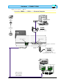
Hardware - CONNECTIONS
CANCELLI AUTOMATICI
-§
RBM8 - INSTALLATION MANUAL
1.1
RBM8 Motherboard - description
LINE FUSE 1,6A
CONTROL BOARD
FUSE 1,6A
MODEM
2
R700 - R800
R700 - R800
4
R501N
R502N
TSP00
LT001
S5000
S6000
S7000
6
3
R700 - R800
2
R700 - R800
1
9
1
A
B
S1 GND OUT
A
B
S1 GND OUT
P1 P2 P3 P4 COM P5 P6 P7 P8 COM
A
B GND
A
B GND
A
B GND
3
A
B
S1 GND OUT
A
B
S1 GND OUT
4
L1 L2
A
3
REM
PC30
4
B
C
10
D
NC NO
BATTERY CHARGER BN1 BATTERY
1
REM
CANCELLI AUTOMATICI
5
DIGITAL INPUT
RBM8
CONTROL BOARD
2
C
OUT1
NC NO
C
OUT2
NC NO
OUT3
C
NC NO
C
NO
OUT4
C
OUT5
NO
C
OUT6
NO
C
OUT7
NO
C
OUT8
7
8
1 - Terminals for powering 230V AC/DC board
2 - Power supply protection fuses (Line) and circuit (Control Board)
3 - Terminals for connecting the BN1 battery charger(optional)
4 - Terminals for connecting the PC30
5 - Terminals for connecting the sensors (radio-controls, keyboards, Card)
6 - Connectors for R700 and R800 boards
7 - Terminals for connecting the input digital devices
8 - Terminals for connecting the devices to control(automations, alarms, traffic lights, etc.)
9 - LED notifying "active circuit" and "communication in progress"
10 - Terminals for connecting the REM extensions
ENGLISH
chapter < 1 > page < 2 >
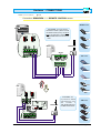
Hardware - CONNECTIONS
CANCELLI AUTOMATICI
RBM8 - INSTALLATION MANUAL
-§
1.2
REM Motherboard - description
9
10
ON
3
4
5
1 - AF43S/AF150/R700/R800
CONTROL BOARD
FUSE 630mA
2
2 - AF43S/AF150/R700/R800
1
3
5
TSP00/LT001
S1 GND S1 GND
2
1
1
2
LINE FUSE 1,6A
REM
4
REM
6
CANCELLI AUTOMATICI
CONTROL
BOARD
A
B GND A
B GND
1
2
REM
11
2
S5000/S6000/S7000
L1 L2
NC NO
C
OUT1
1
NC NO
A
C
OUT2
8
1
2
7
B
1
A
B
2
4
1 - Terminals for 230V ac/dc board powering
2 - Power supply protection fuse
3 - Circuit protection fuse
4 - Terminals for connecting the sensors (keyboards, Card)
5 - Connectors for signal decoding boards (for selectors and sensors) and frequency (radio-controls)
6 - Terminals for antenna connection
7 - Terminals for connecting the input digital devices
8 - Terminals for connecting the devices to control(automations, alarms, traffic lights, etc.)
9 - LED notifying "active circuit"
10 - REM address selector
11 - Terminals for connecting to the RBM8 and/or to another REM
ENGLISH
chapter < 1 > page < 3 >
Hardware - CONNECTIONS
CANCELLI AUTOMATICI
RBM8 -INSTALLATION MANUAL
-§
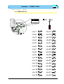
1.3
PC30 - description
10
9
6
8
5
7
11
GND B
A
3
2
1
4
1 - Input power supply, 12/24V AC/DC
2 - 232 serial port for connecting to Personal Computer
3 - Terminals for connecting to RBM8 (RS485 serial port)
4 - 12V AC transformer
5 - Cable complete with 5 m 232 connectors
6 - Keyboard for saving S5000/S6000/S7000 selector codes
7 - Area for saving TOP/TAM/ATOMO transmitters
8 - Area for saving TST01 Card (proximity card)
9 - Area for saving TST02 Card (magnetic swipe cards)
10 - LED notifying "power supply present"
11 - LED notifying "code registered" and "code already present"
ENGLISH
chapter < 1 > page < 4 >
Hardware - CONNECTIONS
CANCELLI AUTOMATICI
RBM8 -INSTALLATION MANUAL
-§
1.4
General layout of the RBM8 system
PC30
A
B B
A
B
B
A
A
C
C
B
RBM8
C
B
B
B
B
B
C
C C
C C
A
A
C
A
C
REM
C
A
B
C
REM
B
SINGLE-SECTION
CONNECTION
max 1000 m
DOUBLE-SECTION
CONNECTION
max 1000 m
A
max 32 REM units for both
types (alternative) of serial
connection, see following
pages
A
B
B
B
C
A
REM
C
B
C
A
REM
C
ENGLISH
chapter < 1 > page < 5 >
Hardware - CONNECTIONS
CANCELLI AUTOMATICI
RBM8 - INSTALLATION MANUAL
-§
1.5
Connection: RBM8 <----> PC30 <----> Personal Computer
Personal Computer
max 5 m
5 m cable
INCLUDING
max 1000 m
RS 232
• for RS232 serial ports
• complete with connectors
PC30
RS485 serial port
GND B
RS232 serial port
A
Power supply input: 12/24V AC/DC
• Use the red
connector
12V AC transformer
INCLUDING
• for 230V AC - 50-60Hz networks
• consumption 800mA
• protected by thermal fuse
• operating temperature from -10 to +40°C
RBM8
RS485 serial port
Cable not included
type recommended:
bipolar shielded
min. 2 x 0.5 mm2
ENGLISH
chapter < 1 > page < 6 >
Hardware - CONNECTIONS
CANCELLI AUTOMATICI
-§
RBM8 - INSTALLATION MANUAL
1.6
Connection: RBM8 <----> REM (single section)
RBM8
RS485 serial port
A
B GND
REM
A
B GND
REM
A
P
Cable not included
type recommended:
bipolar shielded
min. 2 x 0.5 mm2
SINGLE section connection: RBM8 is found
at the end of the cables route
RBM8
REM 1
Each REM is identified by RBM8 by a sequential
progressive numbering (from 1 to 32) independently of
the position along the route of the connection cable;
this number (called also address) must be set on the
related 5 dip switches in the REM motherboard, see
REM 32
from RBM8 to the last REM,
the distance (or the route of
the connection cable) must be
a maximum of 1000 m
{§ 1.11 | p 14}
REM 2
REM 31
1
2
1
2
RS485 serial port
REM
REM
REM
CANCELLI AUTOMATICI
CONTROL
BOARD
A
B GND A
B GND
1
2
REM
S5000/S6000/S7000
at the subsequent REM, for a
maximum of 32 units
(INPUT AND OUTPUT CONNECTABLE
IRRESPECTIVELY TO TERMINAL BOARD 1 OR 2)
ENGLISH
chapter < 1 > page < 7 >
Hardware - CONNECTIONS
CANCELLI AUTOMATICI
-§
RBM8 - INSTALLATION MANUAL
1.7
Connection: RBM8 <----> REM (two sections)
RBM8
A
B GND
A
B GND
A
Cable not included
REM
type recommended:
bipolar shielded
REM
P
TWO section connection: The RBM8 can be
found at any point of the cables route
Each REM is identified by RBM8 by a sequential
progressive numbering (from 1 to 32)
independently of the position along the route of the
connection cable; this number (called also address)
must be set on the related 5 dip switches in the
REM motherboard, see {§ 1.11 | p 14}
1
2
1
REM
RBM8
REM 2
2
REM
REM 1
CANCELLI AUTOMATICI
CONTROL
BOARD
REM 31
from the first to the last REM,
the distance (or the route of
the connection cable) can be
a maximum of 1000 m
section B*
section A*
min. 2 x 0.5 mm2
A
B GND A
B GND
1
2
REM 32
REM
S5000/S6000/S7000
REM
Cable not included
at the subsequent REM*
(INPUT
type recommended:
bipolar shielded
AND OUTPUT CONNECTABLE
IRRESPECTIVELY TO TERMINAL BOARD
1
OR
2)
min. 2 x 0.5 mm2
1
2
1
REM
* the amount of the REMS in serial
connection on the A+B section can be a
maximum of 32 units
2
REM
CANCELLI AUTOMATICI
CONTROL
BOARD
A
B GND A
B GND
1
2
REM
S5000/S6000/S7000
REM
ENGLISH
at the subsequent REM*
(INPUT AND OUTPUT CONNECTABLE
IRRESPECTIVELY TO TERMINAL BOARD 1 OR 2)
chapter < 1 > page < 8 >
Hardware - CONNECTIONS
CANCELLI AUTOMATICI
RBM8 - INSTALLATION MANUAL
-§
1.8
Connection: RBM8/REM <----> REMOTE CONTROL sensor
ATOMO series
RBM8
On the RBM8, you must connect
the R501N receiver (which includes
the AF43S radiofrequency card to insert in the dedicated connector) and
a TOP-A433N antenna on the receiver
itself.
E
CAM
AT01
E
AT02
CAM
TOP-A433N
R501N
E
CAM
AT04
AF43S
TOP series
ATICI
e per
AF150
CAME
TOP-432M
OUT
CAME
TOP-434M
REM
ME
CA
TOP-432SA
REM
RBM8
TOP-432S
AME
C
TOP-432MA
AF43S
TOP-A433N
On the REM, simply insert an AF43S
radiofrequency card
and
connect
a
TOP-A433N antenna to
the REM motherboard.
TAM series
T432
CAME
T434
CAME
T438
CAME
ENGLISH
chapter < 1 > page < 9 >
Hardware - CONNECTIONS
CANCELLI AUTOMATICI
RBM8 - INSTALLATION MANUAL
-§
1.9
Connection: RBM8/REM <----> KEYPAD sensor
RBM8
R800
S5000
R800
CANCELLIAUTOMATICI
2
3
4
5
6
7
8
E
AC/DC
CAME
B
CAME
24/12 0
_
+
REM
A
RBM8
1
S5000
R800
REM
CANCELLI AUTOMATICI
2
3
4
5
6
7
8
E
R800
AC/DC
CAME
A
ENGLISH
1
B
CAME
24/12 0
+
_
chapter < 1 > page < 10 >
Hardware - CONNECTIONS
CANCELLI AUTOMATICI
RBM8 - INSTALLATION MANUAL
-§
1.9
> CONNECTION: RBM8/REM <---->
KEYPAD SENSOR
RBM8
R800
S6000/S7000
R800
CANCELLIAUTOMATICI
1
3
2
5
4
E
6
CAME
WHITE = A
REM
RBM8
BLEU = B
S6000/S7000
1
3
R800
REM
2
4
5
E
6
CAME
CANCELLI AUTOMATICI
R800
WHITE = A
BLEU = B
ENGLISH
chapter < 1 > page < 11 >
Hardware - CONNECTIONS
CANCELLI AUTOMATICI
RBM8 - INSTALLATION MANUAL
-§
1.10
Connection: RBM8/REM <----> CARD READER sensor
Reader for proximity
Card transponder
Proximity card
transponder
RBM8
R700
CA
R700
CANCELLIAUTOMATICI
OL
NTR
CO
TST01
S
CES
AC
TSP00
ME
RED = S1
REM
RBM8
BLACK = GND
R700
OL
NTR
CO
TST01
S
CES
AC
TSP00
CA
ME
RBM8
CANCELLIAUTOMATICI
R700
RED = S1
BLACK = GND
ENGLISH
chapter < 1 > page < 12 >
Hardware - CONNECTIONS
CANCELLI AUTOMATICI
RBM8 - INSTALLATION MANUAL
-§
1.10
> CONNECTION:
RBM8/REM
RBM8
<---->
CARD READER SENSOR
Magnetic card
R700
Swipe reader of
magnetic cards
TST02
ACCESS CONTROL
R700
CANCELLIAUTOMATICI
LT001
BLACK = GND
REM
RBM8
RED = S1
TST02
R700
ACCESS CONTROL
RBM8
CANCELLIAUTOMATICI
R700
LT001
BLACK = GND
RED = S1
ENGLISH
chapter < 1 > page < 13 >
Hardware - CONNECTIONS
CANCELLI AUTOMATICI
RBM8 - INSTALLATION MANUAL
-§
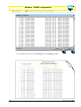
1.11
List of REM addresses
ON
Off
REM
On
1 2 3 4 5
ON
ON
1 2 3
4 5
CONTROL BOARD
FUSE 630mA
2 - AF43S/AF150/R700/R800
2 3 4
1 - AF43S/AF150/R700/R800
1
REM-1
REM-2
REM-3
REM-4
REM-5
REM-6
REM-7
REM-8
REM-9
REM-10
REM-11
REM-12
REM-13
REM-14
REM-15
REM-16
ENGLISH
1 2 3 4 5
1 2 3 4 5
1 2 3 4 5
1 2 3 4 5
1 2 3 4 5
1 2 3 4 5
1 2 3 4 5
1 2 3 4 5
1 2 3 4 5
1 2 3 4 5
1 2 3 4 5
1 2 3 4 5
1 2 3 4 5
1 2 3 4 5
1 2 3 4 5
1 2 3 4 5
REM-17
REM-18
REM-19
REM-20
REM-21
REM-22
REM-23
REM-24
REM-25
REM-26
REM-27
REM-28
REM-29
REM-30
REM-31
REM-32
1 2 3 4 5
1 2 3 4 5
1 2 3 4 5
1 2 3 4 5
1 2 3 4 5
1 2 3 4 5
1 2 3 4 5
1 2 3 4 5
1 2 3 4 5
1 2 3 4 5
1 2 3 4 5
1 2 3 4 5
1 2 3 4 5
1 2 3 4 5
1 2 3 4 5
1 2 3 4 5
chapter < 1 > page < 14 >
CANCELLI AUTOMATICI
C H A P T E R
2
RBM8 - software
SYSTEM
CONFIGURATION
INDEX
arguments
page
System configuration window .................................................................................. 2
Configuring PC30 ..................................................................................................... 3
Selecting the number of REMs connected .............................................................. 4
Assigning a name to the exits connected to RBM8 and REMs ............................... 4
Defining user groups ............................................................................................... 5
Establishing the capacity of sites with traffic-light control .................................... 5
Configuring the control sensors connected to RBM8 ............................................ 6
Sensor Type .............................................................................................................. 6
Sensor function ........................................................................................................ 6
Associating the sensor to a connected exit ............................................................ 7
Associating the sensor to a traffic-light control .................................................... 7
Associating the sensor to a group of users ........................................................... 8
Configuring the exits connected to RBM8 ............................................................... 9
Activating the RBM8 exits ........................................................................................ 9
Relay function ......................................................................................................... 10
Configuring the digital entrances connected to RBM8 ......................................... 11
Associating the digital devices to the exits .......................................................... 11
Configuring the REMs ............................................................................................ 12
Assigning names to the REMs ............................................................................... 12
Configuring the control sensors connected to the REMs ..................................... 13
Sensor Type (REM) .............................................................................................................................................................................. 13
Sensor function (REM) ................................................................................................................................................................... 13
Associating the sensor to a connected exit (REM) ........................................................................................ 14
Associating the sensor to a traffic-light control (REM) ........................................... 14
Associating the sensor to a group of users (REM) ...................................................................................... 15
Configuring the exits of the REMs ......................................................................... 16
Activating the exits of the REMs ............................................................................ 16
Relay function (REM) ........................................................................................................................................................................ 17
Configuring the digital entrances of the REMs ..................................................... 18
Assigning the digital devices to an exit (REM) .................................................................................................. 18
Software - SYSTEM configuration
CANCELLI AUTOMATICI
RBM8 - USER MANUAL
-§
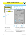
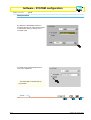
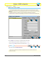
2.1
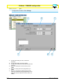
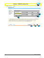
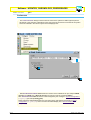
System configuration window
B
A
C
D
E
P
N
L
ABCDEF-
RBM8 configuration dialog
REMs configuration dialog
RBM8 exits configuration dialog
RBM8 digital entrances configuration dialog
PC30 configuration dialog
Button for reading the programming saved on
RBM8
G - Button for saving the programming on RBM8
ENGLISH
M
H
G
F
H - Confirm button for all changes (always valid as
confirmation during programming on the hard
disk; does not affect the memory of RBM8)
L - Button to cancel with the same characteristics of H
M - Resets the alarm exit
N - Blocks all the system at any time
P - Graphical system representation window also
showing - during programming - which parts of
the system we are working on
chapitre < 2 > page < 2 >
Software - SYSTEM configuration
CANCELLI AUTOMATICI
RBM8 - USER MANUAL
-§
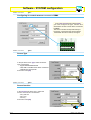
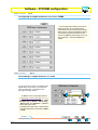
2.2
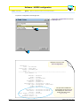
Configuring PC30
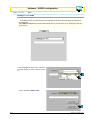
In the PC30 dialog, you must select the
PC’s por t connection the PC30 will be
connected to (normally COM1).
Caution! This operation should be performed
before star ting any programming and/or
configuration operation described in the
following pages or in the sections below,
otherwise - at every request to update and/or
save - the software will flag a
COMMUNICATION ERROR.
ENGLISH
chapitre < 2 > page < 3 >
Software - SYSTEM configuration
CANCELLI AUTOMATICI
RBM8 - USER MANUAL
-§
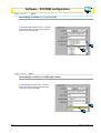
2.3
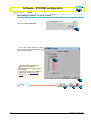
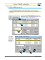
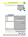
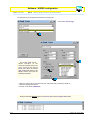
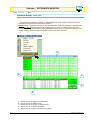
Selecting the number of REMs connected
In the dialog RBM8, Configuration area, set the number of
REMs connected by clicking on the button [No. of
TERMINALS] and by scrolling on the scroll bar
1
2
3
after confirming on [OK], the system-representing window will display the related layout
UPDATE
1
RBM8 - USER MANUAL
-§
2
3
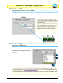
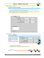
2.4
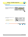
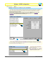
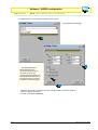
Assigning a name to the exits connected to RBM8 and REMs
Click on [EXITS NAME] ...
1
2
... and type, in the window
EXITS DEFINITION, the desired name for
the exits connected both to RBM8 and to the
REMScollegate sia a RBM8 che ai REM
This procedure is optional: as default,
the system assigns a name to each exit
available in the system (from “Exit 1” to
“Exit 72”).
It is recommended, however, that a name
be given to all the exits as this makes
subsequent configurations easier and
safer.
3
4
UPDATE
1
ENGLISH
2
3
chapitre < 2 > page < 4 >
Software - SYSTEM configuration
CANCELLI AUTOMATICI
RBM8 - USER MANUAL
-§
2.5
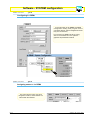
Defining user groups
Click on [GROUPS NAME] ...
1
2
... and in the window GROUPS
DEFINITION, type a name at your
discretion for each group of users (max 8
groups) while also ticking the box Enabled
to activate it (N.B. it is compulsory to
enable at least one group)
3
This procedure is optional; the
system can manage the groups of users
with a default name (Group 1 ÷ Group 8)
but they must however be activated
manually.
4
5
UPDATE
1
RBM8 - USER MANUAL
-§
3
2
2.6
Establishing the capacity of sites with traffic-light control
Click on [TRAFFIC LIGHT] ...
1
... and in the CAR-PARKS MANAGEMENT
window, type in the capacity of each
individual site governed by a traffic light.
3
2
The maximum management
capacity of the entrances/stay-time is
1500 units, to be divided between the
connected traffic lights.
4
UPDATE
1
ENGLISH
2
3
chapitre < 2 > page < 5 >
Software - SYSTEM configuration
CANCELLI AUTOMATICI
RBM8 - USER MANUAL
-§
2.7
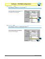
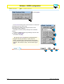
Configuring the control sensors connected to RBM8
R501N
TSP00
LT001
S5000
S6000
S7000
In the Local sensors area of dialog RBM8,
you must configure the type, function and
associations of each control device connected
to RBM8.
The sensor number corresponds exactly to
the sensor connected to the terminal board
marked with the same number, see figure
1
A
RBM8 - USER MANUAL
-§
B
S1 GND OUT
2.8
Sensor Type
In the pull-down menu Type, select the Sensor
Type connected to:
- keypad S5000/S6000/S7000
- TOP, TAM or ATOMO-series radio commands
- TSP00/LT001 transponder
and confirm with [OK]
1
2
3
RBM8 - USER MANUAL
-§
2.9
Sensor function
In the function pull-down menu, select the
function of the sensor connected to:
- entry and exit
- entry only
- exit only
and confirm with [OK]
1
2
ENGLISH
chapitre < 2 > page < 6 >
Software - SYSTEM configuration
CANCELLI AUTOMATICI
-§
RBM8 - USER MANUAL
2.10
Associating the sensor to a connected exit
In the Association pull-down menu, select the
match of the device to one of the connected
exits and confirm with [OK]
1
2
RBM8 - USER MANUAL
-§
2.11
Associating the sensor to a traffic-light control
In the Car-park pull-down menu, select the
match to an exit matched to the traffic-light
control and confirm with [OK]
1
2
ENGLISH
chapitre < 2 > page < 7 >
Software - SYSTEM configuration
CANCELLI AUTOMATICI
RBM8 - USER MANUAL
-§
2.12
Associating the sensor to a group of users
Click on the button [GROUPS] ...
1
... and in the GROUPS window, tick the
group of users to associate the device with;
then confirm with [OK]
2
This procedure is optional; the [ALL]
button associates or disassociates all the
groups of users to the device.
The groups in red are not enabled; to
enable them, see Defining user groups
{§ 2.5 | p 5}
3
UPDATE
1
ENGLISH
2
3
chapitre < 2 > page < 8 >
Software - SYSTEM configuration
CANCELLI AUTOMATICI
RBM8 - USER MANUAL
-§
2.13
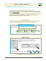
Configuring the exits connected to RBM8
In the EXITS dialog, the exits must be
programmed connected to RBM8 with the type
of function along with any activation interval of
the related relays;
If there are no automations connected, select
or leave “Disabled” as suggested by the menu.
The number of exit, corresponds exactly to
the device connected to the terminal board,
labelled with the same number, see figure
NC NO
OUT1
RBM8 - USER MANUAL
-§
C
NC NO
OUT2
C
NC N
OU
2.14
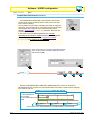
Activating the RBM8 exits
Select the exit (1÷8) and match it with one of
the names/devices that appear in the pulldown menu.
1
2
3
In the pull-down menu of the Local exitsarea, the four exits per traffic light appear as default, and
the normal exits defined in Assigning a name to the exits {§ 2.4 | p 4} plus an exit called Alarm and an exit
called Intrusion alarm;
The exit/control device match is independent of the physical connection of the latter with RBM8 or REM.
ENGLISH
chapitre < 2 > page < 9 >
Software - SYSTEM configuration
CANCELLI AUTOMATICI
RBM8 - USER MANUAL
-§
2.15
Relay function
By default, the monostable function is
proposed; then we can select the time taken
to activate the relays by clicking on the
scrollable scale
If instead we want the bistable function,
click on the related box
The traffic-light controlled exits are
only bistable
UPDATE
1
ENGLISH
2
3
chapitre < 2 > page < 10 >
Software - SYSTEM configuration
CANCELLI AUTOMATICI
RBM8 - USER MANUAL
-§
2.16
Configuring the digital entrances connected to RBM8
In the configuration dialog of the ENTRY
digital entrances, all the supplementary
command and control devices (for example
safety buttons, sensitive footboards, alarms,
etc.) must be programmed which we will
connect to RBM8, and which will act on any
one of the exits - of both the RBM8 and
REMs.
RBM8 - USER MANUAL
-§
2.17
Associating the digital devices to the exits
For each entrance, select an exit/device this
digital device is to work on; you must also
tick the related box, if the device is the
NC -type (normally closed)
3
1
In addition to the normal exits defined
in Assigning a name to the exits {§ 2.4 | p 4},
the pull-down menu shows eleven exits/
function defined “Block”, “Alarm entry”,
“Alarm reset “ and “Entrance” + “Exit” for
each traffic-light control;
The digital entry/exit match is independent
of the physical position of the latter on RBM8
or REM.
2
UPDATE
1
ENGLISH
2
3
chapitre < 2 > page < 11 >
Software - SYSTEM configuration
CANCELLI AUTOMATICI
RBM8 - USER MANUAL
-§
2.18
Configuring the REMs
In the same way as for RBM8, the REMs
configuration dialog must program all the
command devices, exits and digital entrances
they are connected to;
to move from one REM to another, simply
click on the related icon in the system’s
graphical-representation window.
RBM8 - USER MANUAL
-§
2.19
Assigning names to the REMs
The name keyed in here only has a
recognition function, and thus does not
interact with the software.
ENGLISH
chapitre < 2 > page < 12 >
Software - SYSTEM configuration
CANCELLI AUTOMATICI
RBM8 - USER MANUAL
-§
2.20
Configuring the control sensors connected to the REMs
In the Sensors area of the REMn dialog, you
must configure the type, function and associations
of both command devices connected to the REM.
The sensor number corresponds exactly with the
sensor connected to the terminal board labelled
with the same number, see figure
TSP00/LT001
S1 GND S1 GND
1
1
2
2
REM
REM
CANCELLI AUTOMATICI
CONTROL
BOARD
A
B GND A
B GND
1
2
REM
S5000/S6000/S7000
A
C
1
RBM8 - USER MANUAL
-§
2
B
1
A
B
2
2.21
Sensor Type (REM)
In the Type pull-down menu, select the connected
sensor type:
- keypad S5000/S6000/S7000
- TOP, TAM or ATOMO-series radio commands
- TSP00/LT001 transponder
and confirm with [OK]
1
2
3
RBM8 - USER MANUAL
-§
2.22
Sensor function (REM)
In the function pull-down menu, select the
function of the connected sensor:
- entry and exit
- entry only
- exit only
and confirm with [OK]
1
2
ENGLISH
chapitre < 2 > page < 13 >
Software - SYSTEM configuration
CANCELLI AUTOMATICI
-§
RBM8 - USER MANUAL
2.23
Associating the sensor to a connected exit (REM)
In the Association pull-down menu, select the
match of the device to one of the exits
connected and confirm with [OK]
1
2
RBM8 - USER MANUAL
-§
2.24
Associating the sensor to a traffic-light control (REM)
In the Car-park pull-down menu, select the
match to an exit matched to the traffic-light
control and confirm with [OK]
1
2
ENGLISH
chapitre < 2 > page < 14 >
Software - SYSTEM configuration
CANCELLI AUTOMATICI
RBM8 - USER MANUAL
-§
2.25
Associating the sensor to a group of users (REM)
Click on the button [GROUPS] ...
1
... and, in the window GROUPS, tick the
group of users to associate the device with;
then confirm with [OK]
2
This procedure is optional; the
[ALL] button associates or
disassociates all the groups of users
to the device.
The groups in red are not enabled; to
enable them, see Defining user
groups {§ 2.5 | p 5}
3
UPDATE
1
ENGLISH
2
3
chapitre < 2 > page < 15 >
Software - SYSTEM configuration
CANCELLI AUTOMATICI
-§
RBM8 - USER MANUAL
2.26
Configuring the exits of the REMs
In the Local exits area of the REMn dialog,
the type of function and any interval relays
activation interval must be programmed for both
the exits;
If there are no automations connected, select or
leave “Disabled” as suggested by the menu.
-§
RBM8 - USER MANUAL
2.27
Activating the exits of the REMs
Select the exit and match it with one of the
names/devices that appear in the pull-down
menu
1
2
L2
NC NO
OUT1
C
NC NO
C
3
OUT2
In the pull-down menu of the Local exitsarea appear the four exits per traffic light as default and
the normal exits defined in Assigning a name to the exits {§ 2.4 | p 4} plus an exit called Alarm and an exit
called Intrusion alarm;
The exit/control device match is independent of the physical connection of the latter with RBM8 or REM.
The exit number corresponds exactly to the device connected to the terminal board labelled with the
same number, see figure
ENGLISH
chapitre < 2 > page < 16 >
Software - SYSTEM configuration
CANCELLI AUTOMATICI
RBM8 - USER MANUAL
-§
2.28
Relay function (REM)
By default the monostable function is
proposed; then we can select the time taken
to activate the relays by clicking on the
scrollable scale
If instead we want the bistable function, click
on the related box
The traffic-light controlled exits are
only bistable-type
UPDATE
1
ENGLISH
2
3
chapitre < 2 > page < 17 >
Software - SYSTEM configuration
CANCELLI AUTOMATICI
RBM8 - USER MANUAL
-§
2.29
Configuring the digital entrances of the REMs
In the entrances area of the REMn
dialog, we must program the supplementary
command and control devices (for example
safety buttons, sensitive footboards, alarms,
etc.) which we will connect to the REM, and
which will work on any one of the exits - both
RBM8 and REMs.
RBM8 - USER MANUAL
-§
2.30
Assigning the digital devices to an exit (REM)
For each entrance, select an exit/device this
supplementary digital device will work on;
you must also tick the related box, if the
device is the NC -type (normally closed)
3
1
2
In addition to the normal exits defined in Assigning a name to the exits {§ 2.4 | p 4}, the pull-down menu
shows eleven exits/function defined “Blocks”, “Alarm entry”, “Alarm reset” and “Entrance” + “Exit” for
each traffic-light control;
The digital entry/exit match is independent of the physical position of the latter on RBM8 or REMs;
UPDATE
1
ENGLISH
2
3
chapitre < 2 > page < 18 >
CANCELLI AUTOMATICI
C H A P T E R
3
RBM8 - software
TIMINGS
CONFIGURATION
INDEX
arguments
page
Configuration window of the timings ......................................................................... 2
Configuration dialog of the costs ............................................................................... 3
Values for the Prepaid ............................................................................................... 3
Discount levels .......................................................................................................... 4
Configuration dialog of the Time bands ..................................................................... 5
Configuration dialog of the Blocked Days ................................................................. 6
Configuring the Planned openings ........................................................................... 7
Software - TIMINGS configuration
CANCELLI AUTOMATICI
-§
RBM8 - USER MANUAL
3.1
Configuration window of the timings
A
F
B
C
E
D
A - Configuration dialog of costs, credits and
discounts
B - Configuration dialog of the time bands
C - Configuration dialog of blocked days and planned
openings
D - Button for reading the current memory of the
RBM8
E - Button for writing the current programming on
RBM8
F - Button for cancelling for adding/changing data
(valid as cancellation during programming on the
hard disk; does not affect the current memory of
RBM8)
ENGLISH
chapter < 3 > page < 2 >
Software - TIMINGS configuration
CANCELLI AUTOMATICI
RBM8 - USER MANUAL
-§
3.2
Configuration dialog of the costs
In the COSTS dialog the time may be set relating to single credits and a minimum free time, for all
days of the week; it is also possible to define 4 discount levels.
Notes The credits represent only one unit of measurement, which becomes the multiplier of each type of currency
(Euro, Pound sterling, US Dollar etc.) to calculated the related value.
RBM8 - USER MANUAL
-§
3.3
Values for the Prepaid
use the scroll bars to select the
Day and the Time associated to
the Credit (max 2 hours) and the
Minimum free time (max 2
hours);
the [COPY] button copies the
settings for all days of the week;
1
2
3
The Minimum free time is optional;
the default value of the Time associated to the Credit is 1 minute.
UPDATE
1
ENGLISH
2
3
chapter < 3 > page < 3 >
Software - TIMINGS configuration
CANCELLI AUTOMATICI
RBM8 - USER MANUAL
-§
3.4
Discount levels
set up to 4
discount levels,
prices
according to
time and
credits.
2
3
1
This illustration shows 3 discount levels set; the user, after the first half hour has the right to 1
discount credit, after 1 hour, to 3 credits and after an hour and a half, to 5 discount credits.
At any time the discounts may be disables by using the [ELIMINATE] button.
UPDATE
1
ENGLISH
2
3
chapter < 3 > page < 4 >
Software - TIMINGS configuration
CANCELLI AUTOMATICI
RBM8 - USER MANUAL
-§
3.5
Configuration dialog of the Time bands
In the dialog TIME BANDS up to 8 time bands can be set for every day of the week along with
related prepaid values; the AntipassBack time is valid for the total day.
Notes The default settings are: number of bands = 8; time band length = 3 hours; prepaid value = 1 credit; AntipassBack
time = 1 minute
use the scroll bars to
select the day and
time band, and set the
star t and end time
(being sure not to
overlap the bands ),
define the credits per
band and then enable
it; Lastly, set the
AntipassBack time
(valid for the whole
day);
the [COPY] button
copies the settings for
all days of the week;
Notes The extra bands
are to be neutralised by
choosing blocked
1
3
4
2
5
7
6
UPDATE
1
ENGLISH
2
3
chapter < 3 > page < 5 >
Software - TIMINGS configuration
CANCELLI AUTOMATICI
RBM8 - USER MANUAL
-§
3.6
Configuration dialog of the Blocked Days
In the BLOCKED DAYS dialog the blocked or closed days can be set (max 60 days), also for part of
the day, for any day on the year’s calendar.
It is also possible to define two periods of planned opening for every day of the week.
At any moment the Blocked Days can be cancelled with the [ELIMINATE] button or temporarily cleared
by selecting Clear: this last option allows unrestricted access and without Credit debiting to the users,
irrespective of any access configuration planned in Users Configuration>Access {c 4 | § 4.5 | p 9}
Notes As default, the Blocked Days, for 24 hours, are Christmas Day and Italy’s August Bank Holiday.
2
3
4
5
1
To insert another blocked day, click on the [NEW] button (by default, today’s date appears) and use the
scroll bars to select the month, day and, if desired, also set the time to start and end the block.
UPDATE
1
ENGLISH
2
3
chapter < 3 > page < 6 >
Software - TIMINGS configuration
CANCELLI AUTOMATICI
RBM8 - USER MANUAL
-§
3.7
Configuring the Planned openings
The planned openings - for example in a production unit where most entrances and exits of
employees are concentrated into two periods - allows you to activate an exit for one or two time
intervals during the day. After these intervals have elapsed the system resumes its normal functions as
programmed.
Using the button [PLANNED OPENINGS] of the BLOCKED
DAYS dialog, you open the AUTOMATIC EXITS ACTIVATION
window, where you can select the day and exit to which you can
assign one or two periods of planned opening ...
1
2
3
... then activate
the planned
opening for the
period/s desired
with the scroll
bars and by
ticking the outlets
as enabled ...
4
7
5
6
ENGLISH
8
9
chapter < 3 > page < 7 >
Software - TIMINGS configuration
CANCELLI AUTOMATICI
RBM8 - USER MANUAL
-§
3.7
> CONFIGURING THE PLANNED OPENINGS
... if this planned opening is repeated for all days of the week, simply click the button [COPY], otherwise
program the openings for each individual day.
UPDATE
1
2
3
The Copy button copies the latest programming made for all days, irrespective of the day it is
made; to exclude certain days (for example Saturdays and Sundays), disable it in the appropriate box,
or zero the opening start and end times. In the same way, at all times, you can temporarily suspend the
planned opening (by disabling it), or cancel it always (by zeroing it).
ENGLISH
chapter < 3 > page < 8 >
CANCELLI AUTOMATICI
C H A P T E R
4
RBM8 - software
USERS
CONFIGURATION
INDEX
arguments
page
General notes ............................................................................................................ 2
Configuration window of the users .......................................................................... 3
Register a new user .................................................................................................. 4
Saving the user code ................................................................................................ 6
Configuring single-user access ............................................................................... 9
Normal access procedure ....................................................................................... 10
Prepaid access procedure ...................................................................................... 11
Prepaid time-limit access procedure ..................................................................... 13
Personal access procedures .................................................................................. 14
Add a certain number of Users ............................................................................... 15
Users’ status check ................................................................................................. 18
Displays and Prints users’ data and system movements ..................................... 19
Software - USERS configuration
CANCELLI AUTOMATICI
RBM8 - USER MANUAL
-§
4.1
General notes
During the Users configuration operations we recommend frequently saving the selections made: this will
speed up all the programming (thus avoiding frequent checks and reprogramming) and make
programming itself safer.
To this end, use is made of
the [UPDATE] button
the [SAVE USERS]BUTTON
and the graphic button [WRITE USER IN RBM8]
which must be pressed in succession in the order described.
In the following pages, we will indicate the critical moments for saving with the following graphics:
UPDATE
1
2
3
During the operations of Users configuration, is also it worth keeping the Entrances display off so as to
avoid problems of communication with RBM8.
ENGLISH
chapter < 4 > page < 2 >
Software - USERS configuration
CANCELLI AUTOMATICI
RBM8 - USER MANUAL
-§
4.2
Configuration window of the users
A
B
C
D
N
P
M
A - Record sheet of the users’ personal data
B - Saving dialog of the user codes
C - Configuration dialog of the access procedures for
each user (times, costs, limitations, etc.)
D - Dialog of the current situation for each user
E - Button for reading the programming saved on
RBM8
F - Button for saving the programming on RBM8
G - Button for printing the users list and the historic
data registered according to system or user
ENGLISH
L
H
G
F
E
H - Cancellation button for adding/changing data (same
as ‘cancel’ during programming on the hard disk;
does not touch the memory of RBM8)
L - Update button for adding/changing data (same as
‘update’ during programming on the hard disk; does
not touch the memory of RBM8)
M - Window for searching for users by Name
N - Display window of users list
P - Button for accessing the users configuration
procedures (the 4 sheets are empty if there is not
at least one registered user
chapter < 4 > page < 3 >
Software - USERS configuration
CANCELLI AUTOMATICI
RBM8 - USER MANUAL
-§
4.3
Register a new user
In the PERSONALISED dialog, the users’ personal data may be registered such as name,
addresses and group they belong to.
The [NEW SEQUENCE] button is used to generate a number “x” of users with the same type of code
(or command device: Keyboard, Radio-control or Card) see {§ 4.10 | p 15}
1
Click on [NEW] and the fields will appear for adding the personal data ...
ENGLISH
chapter < 4 > page < 4 >
Software - USERS configuration
CANCELLI AUTOMATICI
RBM8 - USER MANUAL
-§
4.3
> REGISTER
A NEW USER
... key in the desired data ...
registration date appears
automatically, whereas all the
other data are optional
2
3
... click on the [GROUP] button ...
... tick the group you want to associate the
user to; then, finally, click on [OK]
The [ALL] button associates or
disassociates the user to/from all the
groups.
The default selection is of “not
belonging”.
The entrance/user group association
4
5
UPDATE
1
2
3
Allocation of the users to at least one Users Group is compulsory.
Becomes however indispensable in the systems in which there are several entrances destined to
different user categories. The typical case is that of a company with entrances devoted to offices, the
production units, suppliers etc, and where some users (for example the surveillance or maintenance
personnel) must be able to access all of these entrances.
ENGLISH
chapter < 4 > page < 5 >
Software - USERS configuration
CANCELLI AUTOMATICI
RBM8 - USER MANUAL
-§
4.4
Saving the user code
In the dialog CODE you must save the user code with the PC30 (or also directly by the software for
the keyboards).
The [CHECK CODE] button is used to test whether there is a code saved, or for reading the code of a
given device.
In the Code type pull-down menu, select the
command device you want to save the code
of, ...
1
2
... click on the button [NEW CODE] ...
3
ENGLISH
chapter < 4 > page < 6 >
Software - USERS configuration
CANCELLI AUTOMATICI
RBM8 - USER MANUAL
-§
4.4
> SAVING THE USER CODE
... and then, within 10 seconds
A- for the TOP, TAM and Atomo radio-controls, click
the button to save by sending the signal to the
dedicated zone on the front panel of PC30 or
B- for TSP00, bring the Card
to save to the dedicated zone
on the front panel of PC30 or
C- for LT001, swipe the Card to save
through the dedicated slit on the front
panel of PC30.
For the S5000, S6000 and S7000 keyboards instead, we are asked if we want to use PC30 to
save the code; if not, saving should be made through the software (see next page)
... by pressing [YES], ...
D- key in the number code in the dedicated
keypad on the front panel of PC30;
The operations for saving the code described above (A - signal sending, B- bringing the Card
closer, C - swiping the Card or D - keying in the code) must take place before the graduated bar seen
in the lower part of the main window scrolls completely (10")
ENGLISH
chapter < 4 > page < 7 >
Software - USERS configuration
CANCELLI AUTOMATICI
RBM8 - USER MANUAL
-§
4.4
> SAVING THE USER CODE
by pressing [NO] ...
... the KEYCODE dialog opens, which allows for an advanced
management of the number code.
First tick the box relating to the keypad model to code
(change the code’s numbers) ...
... then dial the number code by clicking on the numbered
buttons ...
... or give the software the task of generating a random code
by clicking on [RANDOM] ...
... and confirm with [OK]
1
2a
By using the KEYCODE dialog for generating/saving
a keypad code this guarantees - if other users are
present - that there are no codes with the same number;
once generated or dialled, the code can be cancelled and
changed - either wholly or partly - with the buttons [C] or
[CE].
2b
3
UPDATE
1
ENGLISH
2
3
chapter < 4 > page < 8 >
Software - USERS configuration
CANCELLI AUTOMATICI
RBM8 - USER MANUAL
-§
4.5
Configuring single-user access
In the ACCESS dialog, it is possible to program, for each user, different access procedures with or
without costs; in particular:
- access type
- discount
- prepaid amount
- validity and access cost
- time-band access
- type of AntipassBack
By default, the settings are: access type = NORMAL; Discount = NONE; Prepaid = ZERO;
Timebands enabling = ALL; Validity of access = ALWAYS; Access cost = PREDEFINED of the
system (see Timings Configuration>Time Bands {c 3 | § 3.5 | p 5}); AntipassBack Apb = DISABLED.
The default settings, in particular the NORMAL access type, are basically the settings predefined
for accesses into systems other than the charged car-parks, where it is not necessary to evaluate the
access costs while all the remaining management functions (surveillance, accesses time limit,
chronologies print, etc.)are instead requested.
ENGLISH
chapter < 4 > page < 9 >
Software - USERS configuration
CANCELLI AUTOMATICI
RBM8 - USER MANUAL
-§
4.6
Normal access procedure
Leaving the default access at NORMAL, the Discount and
Prepaid areas are not considered, whereas the definition of an
access validity period is optional (in Personalised access see
{§ 4.9 | p 14}), determine the access bands in Timebands enabling ,
select the type of AntipassBack in Apb.
Select the desired access bands, and defined in
{c 3 | § 3.5 | p 5}), all days of the week
1
The button [ALL] enables or disables all the bands
If the time band appears red, it means that it has been
blocked (for all the users) in Timings>Time bands
{c 3 | § 3.5 | p 5}
1
A disabled band stops access; if the user is already inside,
the credit debits will be counted (as set on the following
pages) but only for the “PREPAID” and “PREPAID WITH
TIME LIMIT” modes.
all days
of the week
UPDATE
Select the type of AntipassBack
UPDATE
1
2
3
The AntipassBack is used to stop the fraudulent use of the access devices, for example allowing
more than one vehicle to enter or persons with only one Radio-control or Card.
AntipassBack Time limit means that the user, after passing the entrance, cannot pass back again across
the entrance way for all the time of AntipassBack defined in Timings>Time bands {c 3 | § 3.5 | p 5}.
AntipassBack In/Out means that the user, after passing through the entrance, can only enter again
after having left by way of the normal exit.
ENGLISH
chapter < 4 > page < 10 >
Software - USERS configuration
CANCELLI AUTOMATICI
RBM8 - USER MANUAL
-§
4.7
Prepaid access procedure
By selecting the PREPAID access, it is essential to define the
Prepaid area whereas all the other areas are optional (see Normal
Access {§ 4.6 | p 10} and Personalised Access {§ 4.9 | p 14} for the access
validity)
The term “Prepaid” means a number of credits purchased by the user
having a value defined individually by each system manager (for
example 1.20 Euro/dollar/pound sterling/etc for each credit): RBM8 does
not calculate in currency terms, but only in number of credits.
Set the user-purchased Credits, which will appear in the lefthand box, ...
The left-hand box always represents the last purchase of
Credits by the user.
... and transfer them into the right-hand box with the button [>>]
The right-hand box instead represents, the availability of
Credits the user still has (i.e. after already subtracting the
already-”spent” ones).
If, before “spending” all the credits, the user buys some
more, to add them, click on the button[+]
UPDATE
1
ENGLISH
2
3
chapter < 4 > page < 11 >
Software - USERS configuration
CANCELLI AUTOMATICI
RBM8 - USER MANUAL
-§
4.7
> PREPAID
ACCESS PROCEDURE
At this point, we can select two very different settings for counting the credits.
In the first setting, which we will call PREPAID BY BANDS, we will leave the settings of the credits
defined in Timings>Time bands {c 3 | § 3.5 | p 5}. In this way, the count will vary according the the band
and access day.
In the second, which we will call PREPAID BY ACCESS, we will vary the Number of credits applied
in Personalised access. This setting will debit only one number of credits for each access,
irrespective of the time elapsing, the bands and the access day.
PREPAID BY BANDS
No additional selection to make: RBM8 sums the number of credits of the entry time band to the
numbers of credits of each band that begins within the period between entry and exit.
EXAMPLE OF CALCULATION FOR PREPAID BY BANDS
A
A = time elapsed from
entry until exit
Band 3 = 10 Credits
Band 4 = 15 Credits
Band 5 = 20 Credits
In this example, the user will be debited 10 + 15 + 20 credits
PREPAID BY ACCESS
Click on the button [>>>] in the area Personalised
access, set the number of credits to apply and confirm
with [OK].
UPDATE
1
2
3
In this way, RBM8 will debit a fixed 5 credits for each user entry
ENGLISH
chapter < 4 > page < 12 >
Software - USERS configuration
CANCELLI AUTOMATICI
RBM8 - USER MANUAL
-§
4.8
Prepaid time-limit access procedure
The PREPAID WITH TIME LIMIT mode is similar to the Prepaid
mode and the areas to be defined are the same (to which we refer
for the selection details);
The only difference is the way of calculating the credits to charge the
user which, in this access type, is connected to a time interval (Time
associated to the Credit, not to be confused with time band)
defined in Timings>Costs {c 3 | § 3.2 | p 3}, and which determines the
calculation scanning.
In this mode, in the area Personalised access, it is also
necessary to set, at least 1 credit in Number of credits applied.
This setting replaces the default one in Timings>Time bands
{c 3 | § 3.5 | p 5}, and is valid for all the timebands.
Click on the button [>>>] in the Personalised access
area, set the number of credits to apply and confirm
with the button [OK].
UPDATE
1
2
3
With the mode PREPAID WITH TIME LIMIT, RBM8 multiplies the number of credits set in
Personalised access, for each Time interval associated to the Credit, or fraction thereof, elapsing
from entrance until exit.
EXAMPLE OF CALCULATION FOR PREPAID WITH TIME LIMIT
A = time elapsed from
entry until exit
B = time associated to the
credit
A
B
Band 3
Band 4
Band 5
in this case, the user will be debited (No. of credits applied) x 4 time intervals
ENGLISH
chapter < 4 > page < 13 >
Software - USERS configuration
CANCELLI AUTOMATICI
RBM8 - USER MANUAL
-§
4.9
Personal access procedures
In the ACCESS dialog it is possible also to set, for all the three modes, a validity period for accessing
(subscription type), irrespective of the credits purchased or remaining; this validity can be renewed at any
time.
Also it is possible to select, for each individual user and for the modes PREPAID and PREPAID WITH
TIME LIMIT, a different number of credits to the one set for the time bands (defined in Timings>Time
bands {c 3 | § 3.5 | p 5}).
by clicking on the button [>>>] in the area
Personalised access, the dialog appears of
Access Validity in Days (the default is
“always”) and Number of credits applied
(pre-set to those of the timebands).
Set the validity of the access in days (that
always start from the current date) and transfer
it to the right box with the button [>>>].
Confirm with the button [OK].
2
1
Upon expiry, all accesses will be denied, whatever type of authorization was provided for by
para 4.6, 4.7, 4.8 and also if there are newly-purchased Credits to or residual ones to use up: to revalidate the access, you must set the validity to always; or else add some access days’ validity (the
remaining or purchased Credits will be made usable).
UPDATE
1
ENGLISH
2
3
chapter < 4 > page < 14 >
Software - USERS configuration
CANCELLI AUTOMATICI
RBM8 - USER MANUAL
-§
4.10
Add a certain number of Users
This procedure adds any number of users (up to the maximum number allowed by the system)
with the same characteristics of code type (Keyboard, Radio-control or Card), access type and group
belonging.
It is therefore necessary to configure a user with the desired characteristics, through the
PERSONALISED, CODE and ACCESS dialogs, to then return to PERSONALISED and start up the
3
2
1
4
Click on [NEW] (it is not necessary to complete the data in this phase) ...
... go to the dialog CODE and save a code-type user (see {§ 4.4 | p 6}) ...
... go to the ACCESS dialog and save an access type (see {§ 4.5 | p 9}) ...
UPDATE
1
2
3
... then click on the button [NEW SEQUENCE] ...
If new user is not saved, the procedure will duplicate the last user that was entered (in the
example, user 0001).
ENGLISH
chapter < 4 > page < 15 >
Software - USERS configuration
CANCELLI AUTOMATICI
RBM8 - USER MANUAL
-§
4.10
> ADD
A CERTAIN NUMBER OF
USERS
... select the number of users to add (10 users as default)
and run the procedure with the button [START].
1
2
3
At this point, if the code type is a Keyboard ...
... the software will add them to the list of the users, by generating a different random code for each one;
click the button [END] to terminate the procedure.
UPDATE
1
ENGLISH
2
3
chapter < 4 > page < 16 >
Software - USERS configuration
CANCELLI AUTOMATICI
RBM8 - USER MANUAL
-§
4.10
> ADD
A CERTAIN NUMBER OF
USERS
... if the code type is instead a Transmitter or a Card ...
... after starting up the procedure ...
... you must save through PC30, for each device, the
respective code ({§ 4.4 | p 6})
For each generation of new user, the graduated bar starts
again while waiting for the next code.
... if the code we are saving
is already present ...
... you must click [START] again and save a valid code. Click the button [END] to terminate the procedure.
This applies also when, for whatever reason, you don’t succeed in saving it within 10 seconds
UPDATE
1
ENGLISH
2
3
chapter < 4 > page < 17 >
Software - USERS configuration
CANCELLI AUTOMATICI
RBM8 - USER MANUAL
-§
4.11
Users’ status check
The STATUS dialog allows a test, in real time, of the status of each individual user with reference
to:
- date and time of the last entry
- date and time of the last exit
- the presence or absence of the user within the system
- the total time spent inside the system
- the total number of accesses made
- The number of remaining Credits
Change the Current
Status of the user
Zero the counter of the
total stay time
Zero the counter of the
total number of accesses
The Current status (if present or absent within the system) can be changed at any time, as also
can be zeroed the Total length of stay and Total visits, using the respective buttons
ENGLISH
chapter < 4 > page < 18 >
Software - USERS configuration
CANCELLI AUTOMATICI
RBM8 - USER MANUAL
-§
4.12
Displays and Prints users’ data and system movements
The button DISPLAY/PRINT allows for printing of the users list and the configuration of individual
users; it also allows for the display and/or printing of the movements of single users or of all the
movements registered by the system.
Caution! Before displaying and/or printing the desired lists, RBM8 must save all the data
necessary that is normally stored in its memory on the PC; to do this, the Chronology
management procedure must be carried out as per {c 5 | § 5.2 | p 3}
1a
1b
2
For the User configuration and User chronology it is first necessary to select the user we want
to control; possibly use the dedicated box search by user to find it (type in the name in the surname
box of the PERSONALISED dialog ({§ 4.3 | p 4})
Users list and User configuration
proposes only the print.
User chronology and System
chronology proposes instead the
display and, possibly, the print.
3
ENGLISH
chapter < 4 > page < 19 >
Software - USERS configuration
CANCELLI AUTOMATICI
RBM8 - USER MANUAL
-§
4.12
> DISPLAYS
AND
PRINTS USERS’ DATA
AND SYSTEM MOVEMENTS
To print a users list of the system ...
... select Users list and click on the button
[PRINT].
1
The software directs the print input
to the default Windows printer, so you
should test the status and the properties
of the default printer; for the single-sheet
printers (not continuous sheet), we
recommend selecting an A4 Horizontal
sheet and suitable margins in the printer
properties.
2
Example of printout
of the Users list
Installer :
Date : 22-08-2002
Print type : User list
System : COLLAUDO_GB
Total users : 13
Page : 1
----------------------------------------------------0001 Vincenzi Orlando
0002 Forlani Giacomo
0003 Possamai Federico
0004 Vanzan Francesca
0005 Mattiello Massimo
0006 Castellan Renato
0007 Chinellato Vincenzo
0008 Federici Franco
The symbol on the left of the
>0009 Trevisan Lorenzo
progressive number signals the
0010 Nardi Ivana
presence of the user in the
0011 Toresan Flavio
0012 Zanon Andrea
0013 Rossi Mario
ENGLISH
chapter < 4 > page < 20 >
Software - USERS configuration
CANCELLI AUTOMATICI
RBM8 - USER MANUAL
-§
4.12
> DISPLAYS
AND
PRINTS USERS’ DATA
AND SYSTEM MOVEMENTS
To print the configuration of the single user ...
... select User configuration and click on
the [PRINT] button.
1
2
Example of a print of the
User configuration
Installer :
Date : 22-08-2002
Print type : User date
System : COLLAUDO_GB
Page : 1
--------------------------------------------------------------User Number : 9
Surname :
Name :
Address :
City :
Telephone :
E-mail :
Registration :
Code type:
Code :
Group :
Last Entry
Last Exit
Status
Total lenght of stay
Total visits
Residual credit
ENGLISH
:
:
:
:
:
:
Trevisan
Lorenzo
Via Tarquinio
Treviso
0422564512
@libero.it
15-03-2002 17:28:27
Transponder TSP00/LT00
F017B361F
- - 3 - - - - 26-04-2002 16:58:59
26-04-2002 16:58:40
INSIDE
00:00:13
3
50
The print also includes the
current status of the user as is
also displayed in the STATUS
dialog described to the
{§ 4.11 | p 18}
chapter < 4 > page < 21 >
Software - USERS configuration
CANCELLI AUTOMATICI
RBM8 - USER MANUAL
-§
4.12
> DISPLAYS
AND
PRINTS USERS’ DATA
AND SYSTEM MOVEMENTS
To view/print the chronological movements of a single user ...
... select User Chronology ...
1
2
The Filter gate option
allows selection of the
movements relating only to one
given entrance; the options
Print user name and Print
gate name adds them to the
display and the print (see the
following examples)
3
4
... select the period, day, month and start year and period end you want the detail for ...
... select the appropriate options ...
... and click on the button [DISPLAY] ...
Example of display without options Print user name and Print gate name select
ENGLISH
chapter < 4 > page < 22 >
Software - USERS configuration
CANCELLI AUTOMATICI
RBM8 - USER MANUAL
-§
4.12
> DISPLAYS
AND
PRINTS USERS’ DATA
AND SYSTEM MOVEMENTS
Example of display with only the option Print user name selected
Example of display with the options Print user name and Print gate name selected
5
6
... and, if necessary, click on the button [PRINT], then on [CLOSE] to proceed.
Example of printout of the
Installer :
Date : 22-08-2002
registry
User chronology
Print type : User chronology
System : COLLAUDO
page : 1
-----------------------------------------------------------------------------------------User name
Last access
Port
-----------------------------------------------------------------------------------------(
1) 0009 : Trevisan Lorenzo
26-04-2002 10:41:02 > Cancello principale
(
2) 0009 : Trevisan Lorenzo
26-04-2002 10:41:05 > Cancello principale
(
3) 0009 : Trevisan Lorenzo
26-04-2002 10:41:07 > Cancello principale
(
4) 0009 : Trevisan Lorenzo
26-04-2002 10:41:08 > Cancello principale
(
5) 0009 : Trevisan Lorenzo
26-04-2002 10:44:22 > Cancello principale
(
6) 0009 : Trevisan Lorenzo
26-04-2002 10:45:39 > Cancello principale
(
7) 0009 : Trevisan Lorenzo
26-04-2002 10:46:03 > Cancello principale
(
8) 0009 : Trevisan Lorenzo
26-04-2002 10:46:27 > Cancello principale
(
9) 0009 : Trevisan Lorenzo
26-04-2002 10:47:30 > Cancello principale
(
10) 0009 : Trevisan Lorenzo
27-04-2002 10:47:50 > Cancello principale
(
11) 0009 : Trevisan Lorenzo
27-04-2002 10:52:10 > Cancello principale
(
12) 0009 : Trevisan Lorenzo
28-04-2002 10:58:49 > Cancello principale
(
13) 0009 : Trevisan Lorenzo
26-04-2002 11:04:44 > Cancello principale
(
14) 0009 : Trevisan Lorenzo
27-04-2002 11:06:47 > Cancello principale
(
15) 0009 : Trevisan Lorenzo
27-04-2002 11:08:08 > Cancello principale
(
16) 0009 : Trevisan Lorenzo
26-04-2002 11:11:07 > Cancello principale
(
17) 0009 : Trevisan Lorenzo
26-04-2002 12:11:40 > Cancello principale
(
18) 0009 : Trevisan Lorenzo
26-04-2002 11:12:26 > Cancello principale
(
19) 0009 : Trevisan Lorenzo
26-04-2002 12:12:57 > Cancello principale
(
20) 0009 : Trevisan Lorenzo
26-04-2002 11:13:52 > Cancello principale
(
21) 0009 : Trevisan Lorenzo
26-04-2002 11:15:13 > Cancello principale
(
22) 0009 : Trevisan Lorenzo
26-04-2002 12:15:38 > Cancello principale
(
23) 0009 : Trevisan Lorenzo
26-04-2002 07:16:17 > Cancello principale
(
24) 0009 : Trevisan Lorenzo
26-04-2002 07:16:41 > Cancello principale
(
25) 0009 : Trevisan Lorenzo
26-04-2002 07:17:00 > Cancello principale
(
26) 0009 : Trevisan Lorenzo
26-04-2002 07:21:14 > Cancello principale
(
27) 0009 : Trevisan Lorenzo
26-04-2002 11:23:40 > Cancello principale
(
28) 0009 : Trevisan Lorenzo
26-04-2002 07:24:30 > Cancello principale
(
29) 0009 : Trevisan Lorenzo
26-04-2002 11:24:57 > Cancello principale
(
30) 0009 : Trevisan Lorenzo
26-04-2002 07:35:09 > Cancello principale
(
31) 0009 : Trevisan Lorenzo
26-04-2002 11:35:36 > Cancello principale
(
32) 0009 : Trevisan Lorenzo
26-04-2002 14:14:26 > Cancello principale
(
33) 0009 : Trevisan Lorenzo
26-04-2002 15:34:06 > Cancello principale
(
34) 0009 : Trevisan Lorenzo
26-04-2002 15:34:13 > Cancello principale
(
35) 0009 : Trevisan Lorenzo
26-04-2002 15:34:30 > Cancello principale
ENGLISH
chapter < 4 > page < 23 >
Software - USERS configuration
CANCELLI AUTOMATICI
RBM8 - USER MANUAL
-§
4.12
> DISPLAYS
AND
PRINTS USERS’ DATA
AND SYSTEM MOVEMENTS
To view/print all the chronological movements of the system ...
... select System chronology ...
1
2
The Filter gate option
allows selection of the
movements relating only to
one given entrance; the
options Print user name and
Print gate name adds them to
the display and the print (see
examples on previous pages)
3
4
... select the period, day, month and start year and period end you want the detail for ...
... select the appropriate options ...
... and click on the button [DISPLAY] ...
ENGLISH
chapter < 4 > page < 24 >
Software - USERS configuration
CANCELLI AUTOMATICI
RBM8 - USER MANUAL
-§
4.12
> DISPLAYS
AND
PRINTS USERS’ DATA
AND SYSTEM MOVEMENTS
5
6
... and, if necessary, click on the button [PRINT], then on [CLOSE] to proceed
Example of print of the
Installer :
Date : 22-08-2002
registry System chronology
Print type : Chronology
System : COLLAUDO
Page : 1
-----------------------------------------------------------------------------------------User name
Last access
Port
-----------------------------------------------------------------------------------------(
1) 0009 : Trevisan Lorenzo
26-04-2002 10:41:02 > Cancello principale
(
2) 0009 : Trevisan Lorenzo
26-04-2002 10:41:05 > Cancello principale
(
3) 0009 : Trevisan Lorenzo
26-04-2002 10:41:07 > Cancello principale
(
4) 0009 : Trevisan Lorenzo
26-04-2002 10:41:08 > Cancello principale
(
5) 0009 : Trevisan Lorenzo
26-04-2002 10:44:22 > Cancello principale
(
6) 0009 : Trevisan Lorenzo
26-04-2002 10:45:39 > Cancello principale
(
7) 0009 : Trevisan Lorenzo
26-04-2002 10:46:03 > Cancello principale
(
8) 0009 : Trevisan Lorenzo
26-04-2002 10:46:27 > Cancello principale
(
9) 0009 : Trevisan Lorenzo
26-04-2002 10:47:30 > Cancello principale
(
10) 0009 : Trevisan Lorenzo
27-04-2002 10:47:50 > Cancello principale
(
11) 0009 : Trevisan Lorenzo
27-04-2002 10:52:10 > Cancello principale
(
12) 0009 : Trevisan Lorenzo
28-04-2002 10:58:49 > Cancello principale
(
13) 0009 : Trevisan Lorenzo
26-04-2002 11:04:44 > Cancello principale
(
14) 0009 : Trevisan Lorenzo
27-04-2002 11:06:47 > Cancello principale
(
15) 0009 : Trevisan Lorenzo
27-04-2002 11:08:08 > Cancello principale
(
16) 0009 : Trevisan Lorenzo
26-04-2002 11:11:07 > Cancello principale
(
17) 0009 : Trevisan Lorenzo
26-04-2002 12:11:40 > Cancello principale
(
18) 0009 : Trevisan Lorenzo
26-04-2002 11:12:26 > Cancello principale
(
19) 0009 : Trevisan Lorenzo
26-04-2002 12:12:57 > Cancello principale
(
20) 0009 : Trevisan Lorenzo
26-04-2002 11:13:52 > Cancello principale
(
21) 0009 : Trevisan Lorenzo
26-04-2002 11:15:13 > Cancello principale
(
22) 0009 : Trevisan Lorenzo
26-04-2002 12:15:38 > Cancello principale
(
23) 0009 : Trevisan Lorenzo
26-04-2002 07:16:17 > Cancello principale
(
24) 0009 : Trevisan Lorenzo
26-04-2002 07:16:41 > Cancello principale
(
25) 0009 : Trevisan Lorenzo
26-04-2002 07:17:00 > Cancello principale
(
26) 0009 : Trevisan Lorenzo
26-04-2002 07:21:14 > Cancello principale
(
27) 0009 : Trevisan Lorenzo
26-04-2002 11:23:40 > Cancello principale
(
28) 0009 : Trevisan Lorenzo
26-04-2002 07:24:30 > Cancello principale
(
29) 0009 : Trevisan Lorenzo
26-04-2002 11:24:57 > Cancello principale
(
30) 0009 : Trevisan Lorenzo
26-04-2002 07:35:09 > Cancello principale
(
31) 0009 : Trevisan Lorenzo
26-04-2002 11:35:36 > Cancello principale
(
32) 0007 : Chinellato Vincenzo
26-04-2002 14:07:06 > Cancello principale
(
33) 0007 : Chinellato Vincenzo
26-04-2002 14:07:08 > Cancello principale
(
34) 0007 : Chinellato Vincenzo
26-04-2002 14:07:16 > Cancello principale
(
35) 0009 : Trevisan Lorenzo
26-04-2002 14:14:26 > Cancello principale
(
36) 0009 : Trevisan Lorenzo
26-04-2002 15:34:06 > Cancello principale
ENGLISH
chapter < 4 > page < 25 >
CANCELLI AUTOMATICI
C H A P T E R
5
RBM8 - software
UPDATES, CHRONOLOGY,
PREFERENCES
INDEX
arguments
page
RBM8 Updates .......................................................................................................... 2
Chronology management ......................................................................................... 3
Preferences ............................................................................................................... 4
Software - UPDATES, CHRONOLOGY, PREFERENCES
CANCELLI AUTOMATICI
-§
RBM8 - USER MANUAL
5.1
RBM8 Updates
The UPDATES dialog is used to update, simultaneously or individually, the three key sections of
the configuration: System, Timings and Users.
It also presents as default the update of the system clock.
Before starting up the update procedures, you must have saved all the changes made previously; to
this end, we recommend pressing the buttons indicated here, at least at the end of every configuration
section indicated above.
UPDATE
1
3
2
2
3
1
Tick the section to update and click on [UPDATE], [YES] to confirm the update ...
... and wait for the graduated bar - found in
the lower part of the main window - to
scroll; then click on the button [END]
ENGLISH
4
chapter < 5 > page < 2 >
Software - UPDATES, CHRONOLOGY, PREFERENCES
CANCELLI AUTOMATICI
RBM8 - USER MANUAL
-§
5.2
Chronology management
The dialog CHRONOLOGY MANAGEMENT is used to save the record of all the system’s
movements onto the hard disk.
1
2
3
To manually update the file, select Manual, click on [READ], then close with [OK]
To automatically update the file, select
Automatic, select the time when you want the
update to be made, then close with [OK]. Every
day, at the time indicated, the procedure of
creation/updating will be managed automatically
by the computer.
at the time 00:00:00
2
1
3
Every day, at the time indicated, the
procedure of creation/updating will be
managed automatically by the computer.
Caution! To make sure this happens, the PC
must be on and the RBM8 software active
(also reduced to an icon), so we recommend
adding a link to RBM8:8.exe under the
“Start>Programs>Automatic start-up” folder
(see the MSWindows documentation).
RBM8 keeps up to 30,000 movements stored in its memory: to have a chronological record of the
system’s movements, it is therefore necessary to run this procedure preferably in automatic mode and,
in any case, to run it manually before every check reading/print as mentioned in {c 4 | § 4.12 | p 19}
ENGLISH
chapter < 5 > page < 3 >
Software - UPDATES, CHRONOLOGY, PREFERENCES
CANCELLI AUTOMATICI
RBM8 - USER MANUAL
-§
5.3
Preferences
The PREFERENCES dialog is used to save the name of the system’s installer (optional) which
will appear in the printouts, and determine how the names of the devices connected to the system
are to be indicated in the various system check displays/prints
1
2
3
With Use Entrances Name RBM8 shows the number of the related sensor (for example Rbm8
sens 4 for an RBM8 exit, or Rem 12 sens 2 for an exit of one of the connected REMs).
With Use Exits Name RBM8 shows the names assigned by the manager in System Configuration
{c 2 | § 2.4 | p 4} (for example Entry gate).
These names are displayed/printed in the User Chronology and System Chronology of Users
Configuration {c 4 | § 4.12 | p 19}, and in the last 8 accesses display in the Entrances Monitor
{c 6 | § 6.1 | p 2}.
ENGLISH
chapter < 5 > page < 4 >
CANCELLI AUTOMATICI
C H A P T E R
6
RBM8 - software
ENTRANCES
MONITOR
INDEX
arguments
page
Entrances display - description ................................................................................ 2
Displaying the digital entrances status .................................................................... 3
Displaying the REMs status ...................................................................................... 4
Displaying the system-controlled blocks ................................................................. 4
Displaying the traffic-lights status ............................................................................ 4
Displaying the last 8 accesses to the system ........................................................... 4
Software - ENTRANCES MONITOR
CANCELLI AUTOMATICI
RBM8 - USER MANUAL
-§
6.1
Entrances display - description
The ENTRANCES MONITOR dialog is a utility designed for those systems for which a constant
surveillance of the entrances functioning is required.
Caution! When configuration changes or other operations are made from the software, the entrances
monitor must be off (use the button [OK]), because when it is active, it makes exclusive use of the
communication channel between the PC and RBM8 (precisely to ensure continuous surveillance of the
system’s status), and thus hinders the updates and the changes by software.
A
B
C
D
E
ABCDE-
ENGLISH
Display area of the digital entrances status
Display area of the REMs status
Display area of the system-controlled blocks
Display area of the traffic-lights status
Display area of the last 8 accesses to the system
chapter < 6 > page < 2 >
Software - ENTRANCES MONITOR
CANCELLI AUTOMATICI
RBM8 - USER MANUAL
-§
6.1
> ENTRANCES DISPLAY
DISPLAY AREA OF THE DIGITAL ENTRANCES STATUS
The digital entrances with white background, are not connected or enabled;
The digital entrances with green background are connected, enabled and inactive;
The digital entrances with red background are connected, enabled and are working;
For example, if we have connected a “gate open” sensor of the safety exit on the digital entrance 1, the
red background warns us that, at this moment, it is open and will change to green only when it is
closed.
The labels of the connected entrances may be renamed as desired (max. 13 characters) and will
only appear in this display.
3
1
2
To change the name displayed, double click the related box and
type in the new name in the dialog box; click on [OK] and then on
[SAVE NAMES]
ENGLISH
4
chapter < 6 > page < 3 >
Software - ENTRANCES MONITOR
CANCELLI AUTOMATICI
RBM8 - USER MANUAL
-§
6.1
> ENTRANCES DISPLAY
DISPLAY AREA OF THE REMS STATUS
The REMS with a white background, are not connected or configured (see {c 2 | § 2.18 | p 12});
The REMS with a green background, are connected and are working correctly;
The REMS with red background, are not working correctly due to hardware problems (board
components need replacing, connections to check, etc., which however do not depend on the
configurations);
Caution! If more REMS appear to be connected (with green background) than those we know are
present in the system, this means that, during connection, they were not correctly defined with the
dedicated selector in their motherboard (see {c 1 | § 1.11 | p 14}).
For example, if, in a system with 3 REMS, one of them is defined with the number 6 (i.e. a logical
software address, see previous references), RBM8 will display 6 REMS connected; this does not
however prejudice the system’s working but simply that REMs 4.5 and 6 will appear with a red
background.
DISPLAY AREA OF THE SYSTEM-CONTROLLED BLOCKS
Remote block will appear green if a device is connected
in a digital entrance (for example an emergency button) that is
aimed at voluntarily blocking the system: if activated, the box
will turn red, thus signalling the block.
Block from PC, instead, is always green because it is a
software block and turns red when the related button is
intentionally pressed [BLOCKS RBM8] in the System
Configuration {c 2 | § 2.1 | p 2}
DISPLAY AREA OF THE TRAFFIC-LIGHTS STATUS
The 4 traffic lights connectable to RBM8 will appear red
when the maximum capacity is reached (375) or else the
possibly-modified capacity (less than 375) in the System
Configuration {c 2 | § 2.6 | p 5}
DISPLAY AREA OF THE LAST 8 ACCESSES TO THE SYSTEM
This area shows the last 8 users that have used any entrance of the system (the name of the
entrance depends on the selection made in the PREFERENCES {c 5 | § 5.3 | p 4})
ENGLISH
chapter < 6 > page < 4 >