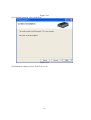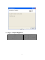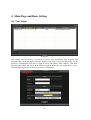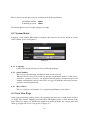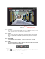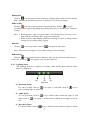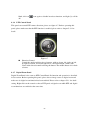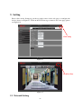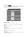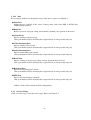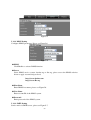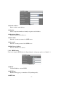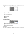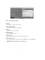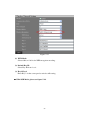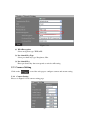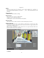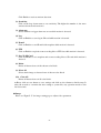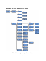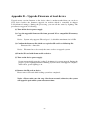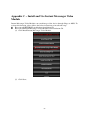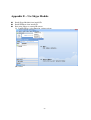
1
Economic Megapixel IP Camera
User Manual
-1-
CAUTION
RISK OF ELECTRIC SHOCK.
DO NOT OPEN!
CAUTION :
TO REDUCE THE RISK OF ELECTRICAL SHOCK,
DO NOT OPEN COVERS (OR BACK).
NO USER SERVICEABLE PARTS INSIDE.
REFER SERVICING TO QUALIFIED
SERVICE PERSONNEL.
It is advised to read the Safety Precaution Guide through carefully before
operating the product, prevent any possible danger.
WARNING: This symbol is intended to alert the user to the presence of un-insulated
“dangerous voltage”.
CAUTION: This symbol is intended to alert the user to presence of important operating and
maintenance (Servicing) instructions in the literature accompanying the
appliance.
Disposal of Old Electrical & Electronic Equipment (Applicable in the European Union
and other European countries with separate collection systems).
This symbol on the product or on its packaging indicates that this product shall not be treated as
household waste. Instead it shall be handed over to the applicable collection point for the recycling
of electrical and electronic equipment. By ensuring this product is disposed of correctly, you will
help prevent potential negative consequences for the environment and human health, which could
otherwise be caused by inappropriate waste handling of this product. The recycling of materials
will help to conserve natural resources. For more detailed information about recycling of this
product, please contact your local city office, your household waste disposal service or the shop
where you purchased the product. The power cord is the main power connection. Therefore,
constantly plug and unplug of the power cord might result in malfunction of the product.
CE / FCC Mark.
This apparatus is manufactured to comply with radio interference requirement.
Do not install the product in an environment where the humidity is high.
Unless the product is waterproof or weatherproof, otherwise it can cause the image quality to
be poor.
Do not drop the product or subject them to physical shocks.
Except for vandal-proof or shockproof product, otherwise it will result malfunctions to occur.
Never keep the product to direct strong light.
It can damage the product.
Do not spill liquid of any kind on the product.
If it gets wet, wipe it dry immediately. Alcohol or beverage can contain minerals that corrode
the electronic components.
℃ ~ 50℃.
Do not expose to extreme temperatures.
Use the product at temperatures within 0
-2-
Table of Contents
1. Product Overview....................................................................................................................................... - 5 1.1 Product Feature .............................................................................................................................. - 5 2. Hardware Overview ................................................................................................................................... - 7 2.1 Hardware Description .................................................................................................................... - 7 3. Installation .................................................................................................................................................. - 9 3.1 Basic Installation............................................................................................................................. - 9 3.1.1
Hardware Connecting Diagram................................................................................................ - 9 3.1.2
Network Setting.......................................................................................................................... - 9 3.1.3
SecuUtility................................................................................................................................. - 10 3.1.4
Device Login ............................................................................................................................. - 10 3.2 Software Installation .................................................................................................................... - 13 3.2.1
Install SecuUtility..................................................................................................................... - 13 3.2.2
Install SecuConverter Tool ...................................................................................................... - 16 3.2.3
Install Secu Series Documents................................................................................................. - 20 3.3 Suggest Computer Equipment..................................................................................................... - 23 4. Main Page and Basic Setting ................................................................................................................... - 24 4.1 User Login ..................................................................................................................................... - 24 4.2 System Status ................................................................................................................................ - 25 4.2.1
Language................................................................................................................................... - 25 4.2.2
Serial Number .......................................................................................................................... - 25 4.2.3
Mac Address ............................................................................................................................. - 25 4.3 Live View Page .............................................................................................................................. - 25 4.3.1
Video Type ................................................................................................................................ - 26 4.3.2
Source........................................................................................................................................ - 26 4.3.3
Digital Zoom ............................................................................................................................. - 26 4.3.4
Utility......................................................................................................................................... - 26 4.3.5
Lighting Status ......................................................................................................................... - 27 4.3.6
PTZ Control Panel ................................................................................................................... - 28 4.3.7
Digital Zoom Panel .................................................................................................................. - 28 5. Setting........................................................................................................................................................ - 29 5.1 Network Setting ............................................................................................................................ - 29 5.1.1
Basic Setting ............................................................................................................................. - 30 5.1.1.1
IP Address Setting ................................................................................................... - 30 5.1.1.2
PPPoE Setting.......................................................................................................... - 31 5.1.1.3
Web Port Setting ..................................................................................................... - 31 5.1.2
Advanced Setting ..................................................................................................................... - 31 5.1.2.1
Port ........................................................................................................................... - 32 5.1.3
Service Setting .......................................................................................................................... - 32 5.1.3.1
DDNS Setting........................................................................................................... - 33 5.1.3.2
SMTP Setting........................................................................................................... - 33 5.1.3.3
RTSP Setting............................................................................................................ - 34 5.1.3.4
Mobile View Setting ................................................................................................ - 35 5.1.3.5
UPnP Setting............................................................................................................ - 35 5.1.3.6
FTP Setting .............................................................................................................. - 36 5.1.4
Wireless..................................................................................................................................... - 36 5.1.4.1
Wireless Network Setting ....................................................................................... - 37 5.2 Camera Setting ............................................................................................................................. - 39 5.2.1
Camera Setting......................................................................................................................... - 39 5.2.2
Streaming Setting ..................................................................................................................... - 45 5.2.3
Event Record ............................................................................................................................ - 46 5.3 Alarm ............................................................................................................................................. - 46 5.3.1
Alarm Setting ........................................................................................................................... - 46 5.4 User Management......................................................................................................................... - 47 5.5 Backup Device............................................................................................................................... - 49 5.6 System............................................................................................................................................ - 50 5.6.1
Basic Setting ............................................................................................................................. - 50 -3-
5.6.2
Advanced Setting ..................................................................................................................... - 51 5.6.3
Time Setting.............................................................................................................................. - 52 5.6.4
DST (Daylight Saving Time) ................................................................................................... - 54 5.7 Serial Port...................................................................................................................................... - 54 Appendix A –Web user interface guide....................................................................................................... - 56 Appendix B – Upgrade Firmware at local device....................................................................................... - 57 Appendix C – Install and Use Instant Messenger Video Module.............................................................. - 58 Appendix E – Time Zone .............................................................................................................................. - 73 Appendix E – Use Skype Module ................................................................................................................. - 75 -
-4-
1. Product Overview
The system is used of IP camera, in order to achieve maximum mutual connectivity and
interoperability, all of this equipment according to leading-industry from front-end to
back-end monitoring structure, provides a variety of standard network protocols and
encryption algorithms. The goal is to expand the monitoring of regional, improve the
monitoring of security level and achieve high compatibility with integrated monitoring
environment.
The system is to use H.264/MJPEG’s video hardware compression chip, can simultaneously
output two kinds of image compression formats, according to different monitoring
environment to adjust to fit the suitable way. To provide high transmission quality, low
transfer rate, low delay, use a less of hard disk storage space and other features of the image,
moreover, support low delay of two-way voice.
1.1 Product Feature
Megapixel image; frame rate can be up to 25 at 1280x800.
Support H.264 / MJPEG codec, video quality is adjustable.
Support ADPCM codec, two way audio is supported.
Support high performance network transmission algorism, provide low-latency
video and audio stream.
Support event and schedule recording.
Support multiple event search (alarm, motion, video loss…) for basic and intelligent
playback.
Support motion detection; detection area and sensitivity are adjustable.
Support multiple alarm and event trigger.
Support RS485 interface, and PTZ control panel.
Video stream bit rate, frame rate and resolution are adjustable.
Multi-language supported.
Support multi-level password and protection in order to provide the highest security.
Support SD Card store pre-event and post-event recording and remotely backup
manually. (Bundled software supported)
-5-
Support remote setup, live view, recording, snapshot, ftp and firmware upgrade by
web page or bundled software.
Provide SecuUtility for device searching.
Network protocol supported: HTTP, UPnP, DNS, DDNS, RTSP, RTP, RTCP, TCP/IP,
UDP/IP, ICMP, DHCP, PPPoE, FTP, NTP, SMTP, Multi-Casting.
Support auto re-connecting after network or power shortage.
Support digital zoom on web page.
Free bundle 32 channel surveillance software. Support maximum 32 channels live
view and 16 channels playback.
Support hardware reset function.
-6-
2. Hardware Overview
2.1 Hardware Description
Figure2-1
LIGHT SENSOR
Detect incoming light sensor. While the incoming light is too low, image will display in
monochrome automatically.
MICROPHONE
Built-in microphone.
USB
External USB slot, user can use it for wireless module.
RESET
When system is frozen, please push the reset button with suitable object and keep it
depressed for 5 seconds, after the power light is blinking, then release the reset button,
the system will finish rebooting procedure in one minute. When the power light is on;
the device is booted up successfully.
AUDIO-OUT
Connect to external audio devices for audio output, like speaker. Remote audio will
output from this connector.
AUDIO-IN
Connect to external audio devices for audio input, like microphone.
SD CARD SLOT
Support SD card type SD1.1 to SD2.0. Device doesn’t support SD card hot swapping,
please insert or remove SD card while system is off.
-7-
12 DC/1A
Connect to 12V DC power adapter.
ETHERNET
Connect to Ethernet network.
RS485/ALARM
Connect external device or RS-485 to keyboard or PTZ camera with Mini Dim Cable,
which is an accessory in product package. Please refer to figure 2-2 for pin definition.
ALARM
COM N.O.
D- D+
G
IN
SENSOR-IN
Figure 2-2
—
—
Pin definition in figure 2-2 as follows
a. COM
Connect point that corresponds to alarm out.
Connect to N.O. alarm output device.
b. ALARM N.O.
c. D— Connect to external device, such as PTZ camera or PTZ control
keyboard.
d. D+
— Connect to external device, such as PTZ camera or PTZ control
keyboard.
e. G
— Ground wire.
f. Sensor In
— Connect to alarm input sensor.
Color wire definition of Mini Dim in product package as follows:
Black: ground wire
Red: sensor in wire
Orange: D+ wire
Gray: D- wire
Blue: COM wire
Brown: N.O.wire
-8-
3. Installation
3.1 Basic Installation
3.1.1 Hardware Connecting Diagram
2
1
Figure3-1
(1) Connect the 12V DC adaptor to the power jack on the rear panel of the IP camera.
(2) Use Ethernet cable to make connection from the Ethernet 10/100 RJ45 socket on
the IP camera to the PC.
3.1.2 Network Setting
After completing the basic hardware connection, make sure that the PC and the IP
camera IP address are both in the same network segment. Example: Setup preset IP
camera IP to 192.168.100.100 and configure your desktop IP address as the Figure
3-2 below.
:
:
:
Setup format
IP Address 192.168.100.xxx
Subnet Mask 255.255.255.0
Default Gateway 192.168.100.1
※Note
:
xxx address ranges from 1~254,
please avoid using “100” which
has been used by IP camera.
Figure3-2
-9-
3.1.3 SecuUtility
(1) Please install SecuUtility from the product CD. (Please refer to chapter 3.3.1 for
installation procedures)
(2) Execute the SecuUtility.
(3) After starting SecuUtility, the program will automatically search and display all of
the digital IP camera devices on local area network, please see the Figure 3-3.
(4) Based on the IP address, please choose which device you would like to access, the
default IP address on the device is 192.168.100.100.
(5) Double click on the IP address, will automatically open the selected digital IP
camera web image.
(6) Click on the refresh button on the left bottom side of the utility page to re-search
devices on the network.
Figure3-3
3.1.4 Device Login
Once you have logged in, you will see a pop-up information bar requiring your attention for
installing ActiveX Control, use mouse right click to install ActiveX Control, please see
Figure3-4.Then a window will appear asking you to confirm whether or not you want to
install the ActiveX control. Select “Install”, please see Figure 3-5. After Active Control has
been successfully setup, website login page appears on the screen, please see Figure3-6.
Figure3-4
- 10 -
Figure3-5
Figure3-6
- 11 -
Figure3-7
:
:
。
。
。
(1) Figure 3-7, follow the steps below to login the device —
a. Enter the default username admin
b. Enter the default password admin
c. Click on the login button
(2) Login complete, enter real-time video view page, please see Figure3-8.
Figure 3-8
- 12 -
:The default video format is MJPEG, if user cannot see video stream with H.264
Note
format, please install FFDshow decode software from product CD.
3.2 Software Installation
Please install following software from product CD.
3.2.1 Install SecuUtility
(1) Click Install SecuUtility Tool
Figure 3-11
(2) Click Next.
- 13 -
Figure 3-12
(3) Select Installation Folder.
- 14 -
Figure3-13
(4) Confirm Installation, please click Next.
Figure 3-14
(5) Installation complete, please click Close to exit.
- 15 -
圖 3-15
3.2.2 Install SecuConverter Tool
(1)Click Install SecuConverter tool
- 16 -
Figure 3-16
(2) Click Next
- 17 -
Figure 3-17
(3) Select Installation Folder.
Figure3-18
(4) Confirm Installation, please click Next.
- 18 -
Figure 3-19
(5) Installation complete, please click Close to exit.
- 19 -
Figure 3-20
3.2.3 Install Secu Series Documents
(1) Click Install Secu Series Documents.
Figure 3-21
(2) Click Next.
- 20 -
Figure 3-22
(3) Select Installation Folder.
- 21 -
Figure 3-23
(4) Confirm Installation, please click Next.
Figure 3-24
(5) Installation complete, please click Close to exit.
- 22 -
Figure 3-25
3.3 Suggest Computer Equipment
CPU
RAM
Audio Card
Operation System
Browser
Intel® Core 2 Due E7200 or above
1GB or above
Needed
Microsoft Windows 2000/XP
IE6 or above
- 23 -
4. Main Page and Basic Setting
4.1 User Login
Figure4-1
One minute after the device is powered on, please start SecuUtility. The program will
automatically search and display all of the digital server devices on local LAN, please see the
Figure4-1. Information from left to right as below, IP address, Mac Address, Web Port,
Stream Control Port, and Server Model. Please click on the device you would like to access,
and then enter login page of the device, please see Figure4-2.
Figure4-2
- 24 -
Please enter username and password, and then click on the login button.
:admin
:admin
a. Default username
b. Default password
For limited function, please login with guest account.
4.2 System Status
Language, serial number, Mac Address, hardware and software version are shown in system
status column, please see Figure4-3.
Figure4-3
4.2.1 Language
Click on the drop down menu to choose different language.
4.2.2 Serial Number
This is for password backup mechanism when password is lost.
When password is lost, please contact us and provide the MAC Address of the device,
(format as: xx:xx:xx:xx:xx:xx ), our support team will generate an universal password
with the serial number and once the device is logged in with this universal password,
it will be invalid automatically.
4.2.3 Mac Address
This is a 12 digits serial number; it is a global unique Ethernet card address.
4.3 Live View Page
After login, quad image will be shown, the operating item from left to right on the tool bar
are Video Type, Source, Digital Zoom and Utility. The lighting status is at the bottom of the
page. Please see figure 4-4. If PTZ and digital zoom function enable, the control panel will
show up at right side of live view, please see figure 4-7.
- 25 -
Figure4-4
Lighting Status
4.3.1 Video Type
This device supports H.264 and MJPEG video type, the MJPEG is default type, click
on the drop down menu to select different type for video type.
4.3.2 Source
Device receive single camera source. While digital zoom enables, source could be
chosen as digital zoom or camera. For digital zoon setting, please refer to chapter
5.2.1.
4.3.3 Digital Zoom
Zoom in from the center of the image, default zoom ratio from X1, X2 to X4.
4.3.4 Utility
The utility items from left to right are full screen, snapshot, recording, stop recording,
audio and broadcast. Please see Figure4-5.
Figure4-5
Full Screen
Click on
icon or double click on the image, the full screen mode will be activated.
Double click on the image can return to standard mode.
- 26 -
Snapshot
Click on
icon, the image will be snapshoot, all image taken will be stored in default
path., regarding the default path, please see charter 5.6.2 (advanced setting).
Recording
Click on
icon, the recording will be start immediately; click on
icon, the
recording will be stopped. Regarding the default path, please see charter 5.6.2 (advanced
setting).
:1. Recording file is split every five minutes; once the hard drive free space is less
Note
than 1GB, the recording will be stopped automatically.
2. When switch to other channels which are not being recorded, or change camera
settings, the recording will be stopped.
Audio
Click on
icon to play audio, click on
icon again to mute audio.
︰Please refer to chapter 5.2.1 for Audio settings (Camera Setting).
Note
Broadcast
Click on
icon to enable broadcast function; audio can be sent from control room to
camera site. Click on
icon again to stop broadcast function.
4.3.5 Lighting Status
The lightings from left to right are recording, audio and broadcast function status.
Please see Figure4-6.
(1)
(2)
(3)
Figure4-6
(1) Recording Status
It is off by default, click on
icon, light (1) will blink, click on
stop recording, light (1) will be off.
icon to
(2) Audio Status
It is off by default, click on
blink, click on
off.
icon to enable audio in function, light (2) will
icon again to disable audio in function, and light (2) will be
(3) Boradcast Status
It is off by default, click on
icon to enable broadcast function, light (3) will be
- 27 -
blink, click on
off.
icon again to disable broadcast function, and light (3) will be
4.3.6 PTZ Control Panel
This panel can control PTZ camera direction, please see figure 4-7. Before operating this
panel, please make sure that the PTZ function is enabled; please refer to chapter 5.2.1 for
detail.
Figure4-7
Direction Control
Control the angles and direction of camera, with up, down, left, right, up left,
up right, down left, and down right. Press a direction button; camera will
rotate in this direction until releasing the button. The middle button is for back
to home.
4.3.7 Digital Zoom Panel
Digital Zoom Panel is the same as PTZ Control Panel. Its function and operation is described
in last section. Before operating this panel, please choose image source as digital zoom and
make sure its digital zoom function has been enabled. Please refer to chapter 5.2.1 for detail
setting. Right click on the control to choose PTZ panel or digital zoom while PTZ and digital
zoom functions are enabled at the same time.
- 28 -
5. Setting
Please click on the Setting tag on the top right corner of the web page to configure the
device, please see Figure5-1. Click on the LiveView tag to return to live view page, please
see Figure5-2.
Click Setup
Figure5-1
Click LiveView
Figure5-2
5.1 Network Setting
- 29 -
5.1.1 Basic Setting
Please click on the
icon to configure network setting, and click on Basic tag to
set IP address of the device. User can select Static IP mode, DHCP mode or PPPoE mode,
after change, please click on Save button. Please see Figure5-3.
Figure 5-3
5.1.1.1 IP Address Setting
The device supports DHCP and static IP mode. Please see Figure5-3.
DHCP
Click on Enable to activate DHCP; the device will get IP address from DHCP server.
IP Address
Enter IP address of the device.
Subnet Mask
Enter a subnet mask of the device, If IP address of this device is changed, adjust the
subnet mask accordingly.
Gateway
Enter the IP address of the gateway (the router).
Primary DNS
Defines the IP address of the primary DNS server. This is used for identifying this device
by name instead of IP address.
- 30 -
Secondary DNS
The IP address of the secondary DNS server; it will be used once the primary DNS server
fails.
5.1.1.2 PPPoE Setting
Connect the device to internet by PPPoE through ISP. Please see Figure5-3.
PPPoE
Click on enable to activate PPPoE function.
User Name
Enter the user name of the ISP account.
Password
Enter the password of the ISP account.
5.1.1.3 Web Port Setting
Enter the port number which the device to use HTTP protocol. The port number is 80 by
default, if user would like to access the device with different port number, please assign
the new port number. The hyperlink format as below:
http://192.168.100.100:8080
5.1.2 Advanced Setting
Click on the advanced setting tag to enter the advanced setting page. Please see Figure5-4.
Figure 5-4
- 31 -
5.1.2.1 Port
Reserved port numbers for designated usage of the device, please see Figure5-4.
Start Port
Define the port segment of the device. Setting range starts from 2001 to 65530. Port
12004 shall be retained.
End Port
Refer to previous start port setting, automatically calculate port segment of the device.
Control Port
Port for sending control message.
(This port number will be automatically assigned based on start port and end port)
Video Streaming Port
Port for sending video stream.
(This port number will be automatically assigned based on start port and end port)
Audio Streaming Port
Port for transmitting audio stream.
(This port number will be automatically assigned based on start port and end port)
Event Port
Port for sending event message (alarm, motion detection and video lost).
(This port number will be automatically assigned based on start port and end port)
Broadcast Port
Port for broadcasting audio stream.
(This port number will be automatically assigned based on start port and end port)
FTP Port
Port for file transferring to client PC.
(This port number will be automatically assigned based on start port and end port)
※Please click on Save button to finish configuration.
5.1.3 Service Setting
Click on service tag to enter the service page. Please see Figure5-5.
- 32 -
Figure5-5
5.1.3.1 DDNS Setting
Configure DDNS parameters. Please see Figure5-6.
Figure5-6
DDNS
Click Enable to activate DDNS function.
Server
Select DDNS service system: dyndns.org or dhs.org, please access the DDNS websites
below to apply account and password.
http://www.dyndns.com
http://www.dhs.org
Host Name
Enter DDNS host name, please see Figure5-6.
User Name
Enter account ID of the DDNS system.
Password
Enter password of the DDNS system.
5.1.3.2 SMTP Setting
Send e-mail via SMTP server, please see Figure5-7.
- 33 -
Figure5-7
Sender Address
Enter a sender e-mail address.
Number
Select a sequence number to identify recipient e-mail address.
Recipient Address
Enter recipient E-mail addresses.
User Name
Enter the account user name for SMTP server.
Password
Enter the account password for SMTP server.
Mail Server Address
Enter the SMTP server address.
5.1.3.3 RTSP Setting
The device supports RTSP function. Regarding the setting page, please see Figure5-8.
Figure 5-8
RTSP
Click on Enable to activate RTSP.
RTSP Port
RTSP streaming port, port number is 554(unchangeable).
RTP Port
- 34 -
RTP streaming port, port number is 5004(unchangeable).
RTCP Port
Streaming control port, port number is 5005(unchangeable).
Live View Video Stream With QuickTime
Please follow the steps below to live view video stream with QuickTime:
(1) Starts QuickTime
(2) Select File and then open URL from the function bar. Please enter IP address of the
device in the pop-up window. The below link shows an example by the default address
rtsp://192.168.100.100/XXX
Notice: 1. This service is workable while the RTSP is enabled on web page.
2. Only one connection can access the device while using this service.
3. Please follow below procedures to setup QuickTime while the QuickTime
version is later than 7.5.5 and not able to view live image.
Select Edit > Preferences > QuickTime Preferences; click Advanced tag and
disable “Enable Direct3D video acceleration” item.
5.1.3.4 Mobile View Setting
Enable mobile view function, the device will be able to with mobile service. User can
connect device image with 3G cell phone. Please see Figure5-9.
Figure 5-9
Please input below IP address for mobile view link:
http://ip address/m1.htm
Notice: User can connect to above links with IE on PC to see weather the function works or
not. The smooth on the mobile web page can be modified: high is one frame per second,
medium is one frame every three seconds, low is one frame every five seconds.
5.1.3.5 UPnP Setting
Enable UPnP function, the device will be able to be found in My network places on your
desktop. Please see Figure5-10.
Notice: UPnP function should be enabled on the device and desktop.
Figure5-10
- 35 -
5.1.3.6 FTP Setting
Enable FTP function to upload file to FTP servers. Please see the Figure5-11 for the setting
page.
Figure5-11
FTP Server
Please enter the FTP server address.
FTP Port
FTP port number, default port is 21.
Account
Enter the FTP account.
Password
Enter the FTP password.
5.1.3.7 FTP Upload Image
Enable this function to start uploading image to FTP server regularly.
Status
Enable to upload live image to FTP server with fixed interval.
Duration(sec.)
Select the frequency of uploading image.
5.1.4 Wireless
This function only supports device with wireless module. Please click on Wireless tag to
enter setting page, please see figure 5-12.
- 36 -
Figure 5-12
5.1.4.1 Wireless Network Setting
WLAN
Click Enable to active wireless function.
Communication Mode
Set communication mode as infrastructure.
SSID
Enter SSID of wireless AP router.
Wi-Fi Channel
Select Wi-Fi channel: Auto, 1 ~ 11.
Wireless Mode
Wireless mode is 802.11b/g, system will select automatically.
Wireless Encryption
Select wireless encryption type: Open System, WEP(Shared key), and WPA-PSK.
◎WEP(Shared key) Mode, please see as figure 5-13.
- 37 -
Figure 5-13
(1) WEP Mode
Select 64bit or 128 bit for WEP encryption encoding.
(2) Default Key ID
Select Key ID from 1 to 4.
(3) Key1~Key4
Enter Key 1~4 that correspond to wireless AP setting.
◎ WPA-PSK Mode, please see figure 5-14.
- 38 -
Figure 5-14
(1) WPA Encryption
Select encryption type: TKIP, AES.
(2) Pre-shared Key Type
Select pre-shard key type: Passphrase, Hex.
(3) Pre-shared Key
Enter pre-shared key that corresponds to wireless AP setting.
5.2 Camera Setting
Click on the
icon of the web page to configure camera and stream setting.
5.2.1 Camera Setting
Please see Figure5-15 for camera setting page.
- 39 -
Figure5-15
Title
Define the camera name, the characters can be Arabic alphabet 0~9, capitalized or
non-capitalized English alphabet, and symbol“-”, “_”and“.”. The maximum inputs are 20
characters.
Sound Record
Enable audio function while recording.
Audio Source
Select audio source is Line-in or Microphone.
(1)Line-in: receive audio from audio-in.
(2) Microphone: receive audio from built-in microphone.
Camera Mode
Select indoor mode or outdoor mode base on the shooting range of camera.
Motion Detection
Set up object movement range; system default set whole image as detection area. Once
the motion is triggered, same region motion detection will not be trigger within 10-15
seconds. Please see Figure5-16.
There are three color blocks to define detection area: red, green and blue. Each color
block can define detection area separately.
Figure5-16
(1) Enable
- 40 -
Click Enable to activate motion detection.
(2) Sensitivity
Click on the drop down menu to set sensitivity. The higher the number is, the more
sensitive the motion detection is.
(3) Alarm out
Select whether to trigger alarm out or not while motion is detected.
(4) Log
Click on Enable to store log in SD card while motion is detected.
(5) E-mail
Click on Enable to send E-mail with snapshot while motion is detected.
(6) FTP
Click on Enable to upload event recording files to FTP site while motion is detected.
(7) Save To SD Card
Click on Enable to save snapshot and event recording files to SD card while motion is
detected.
(8) Delete
Delete all detected area of the chosen color block.
(9) Select All
Select whole image as detected area of chosen color block.
(10) Clear All
Delete all detected area of all color block.
※Please click on save button to save settings and click on close button to finish setup. It
takes 10 seconds to overwrite the new setting to system file; any operation needs to wait
for 10 seconds.
Image
Please see Figure5-17 for image setting page to adjust video parameter.
- 41 -
Figure5-17
(1) Image Color
Select image color in color or memo.
(2) Brightness
Adjust the video brightness parameter.
(3) Saturation
Adjust the video saturation parameter, the higher the parameter number is, the more
the image saturated.
(4) Contrast
Adjust video contrast parameter, the higher the value is, the higher the contrast range
is.
(5) Flip
Enable this checkbox to flip video up-down.
(6) Mirror
Enable this checkbox to mirror video left-right.
※Please click on save button to save settings and click on close button to finish setup.
OSD (On Screen Display)
Enable the OSD function on the OSD page, please see Figure5-18.
- 42 -
◎Real Time OSD
Figure 5-18
OSD on live view. Only display while the live view source is chosen as single channel.
(1) Display Item
Click on Item or FPS checkbox, for the OSD setting, please see charter 5.2.1.
(2) Position
Click on the drop down menu to select the placement for the OSD display,
Top-Left, Top-Right, Bottom-Left and Bottom-Right.
(3) Color
Select OSD font color.
(4) Background Color
Click on the drop down menu to select OSD background color, black, white and
transparent.
(5) Transparency
Click Enable to make the OSD word transparent.
◎Recording OSD display
OSD on the recording video clip. All cameras on the device will use the same setting
while any of them make changes.
(1) Date/Time
- 43 -
Click on Enable to embed Date/Time information on video.
※ Please click on save button to save settings and click on close button to finish setup.
PTZ
PTZ (Pan Tilt Zoom) control setting, please see figure 5-19.
◎ PTZ Setting
Figure 5-19
When the PTZ status enable, user can operate PTZ function by PTZ control panel,
please refer to chapter 4.3.6 for detail operation.
(1) Enable
Click on Enable to activate PTZ control.
(2) Protocol
Select Protocol type for PTZ camera. Available choices are Palco D and Palco P.
(3) Address
Enter PTZ address. The value should be set between 0 and 255.
(4) Zoom Speed
Select zoom speed for PTZ. The bigger the value is, the faster the camera zoom.
(5) Focus Speed
Select focus speed for PTZ. The bigger the value is, the faster the camera
focus.
(6) Tilt Speed
Select tilt speed for PTZ. The bigger the value is, the faster the camera zoom.
- 44 -
(7) Pan Speed
Select pan speed for PTZ. The bigger the value is, the faster the camera zoom.
◎ Digital Zoom Setting
When the PTZ status enable, user can operate digital zoom panel in live view, please refer
to chapter 4.3.7 for detail operation.
(1) Status
Click on Enable to activate digital zoom function. Stream resolution should set in
1280x800 to enable this function.
(2) Width
The width of the live view frame when image source is digital zoom in live view.
Setting range is from 352 to1280.
(3) Height
The height of the live view frame when image source is digital zoom in live view.
Setting range is from 240 to 800.
5.2.2 Streaming Setting
Setting image streaming paremeters. Please see Figure 5-20. Please note that the streaming
setting only applies to video format as MJPEG. If the video format is H.264, frame rate is
13~15 per second in every resolution.
Figure5-20
Resolution
Click on the resolution drop down menu to select the resolution:1280x800, 640x400,
320x192.
Bit Rate
Click on the drop down menu to select the bit rate of the video streaming. Setting range is
between 128Kbps and 4Mbps. Lower bit rate consumes less bandwidth but delivers lower
quality images. High bit rate consumes more bandwidth but delivers higher quality
images.
FPS
Click on the drop down menu to select the frame rate, the higher the frame rate is, the
smoother the video stream will be.
- 45 -
5.2.3 Event Record
Configure pre-event and post-event recording buffer. Please see Figure 5-21.
Figure5-21
Pre-event Recording
Click on the drop down menu to select pre-event recording duration time.
Post-event Recording
Click on the drop down menu to select post-event recording duration time.
※Please click on save button to save settings and click on close button to finish setup.
Convert event recording files with SecuConverter
Event recording data are raw file when you retrieve them from SD card or FTP. Please
convert those data to AVI format with SecuConverter. (Please refer to chapter 3.3.2 for
SecuConverter installation) Please follow the below procedures to execute SecuConverter.
(1) Start SecuConverter, please see figure 5-22.
Figure 5-22
(2) Click Open File to choose event recording file.
(3) Click Save File to choose saving folder for avi files.
(4) Click Convert, and then click Finish to exit.
5.3 Alarm
Please click on the
icon on the upper left corner of the setting page to configure alarm
setting. The same event will not trigger alarm continuously.
5.3.1 Alarm Setting
Please see Figure5-23 for the alarm setting.
- 46 -
Figure5-23
Status
Click Enable to activate alarm function.
Alarm Out
Select whether to trigger alarm out or not while alarm is triggered.
Log
Click on Enable to save log in SD card while alarm is triggered.
E-mail
Click on Enable to send E-mail with snapshot while alarm is triggered.
FTP
Click Enable to upload event recording files to FTP site while alarm is triggered.
Save to SD Card
Click Enable to save snapshot and event recording files to SD card while alarm is
triggered.
※Please click on save button to save settings and click on close button to finish setup.
5.4 User Management
Click on
account.
icon on upper left corner of the setting page to configure user
The device provides 4 different security levels, administrator (full permission), supervisor,
operator and guest (lowest permission). Please see Figure5-24.
- 47 -
Figure5-24
Change Password
Enter the original password and new password, click on change button to finish password
change.
:
Note Password of operator and guest accounts are not changeable, if user wants to
change the password of operator and guest accounts, please login as administrator or
supervisor, and delete operator or guest account, and create new accounts.
Create Account
Enter username and password, select the security level and click on add button to add a
new user. The maximal users can be set up to 15. The account name characters should
follow the restriction below:
(1) Enter user name (the characters can be Arabic alphabet 0~9, capitalized or
non-capitalized English alphabet, and symbol“-”, “_”and “.”. The
maximum inputs are 32 characters.)
(2) Enter password (the characters can be Arabic alphabet 0~9, capitalized or
non-capitalized English alphabet, and symbol“-”, “_”and “.”. The
maximum inputs are 32 characters. English upper and lower case are seen
as different character.)
(3) Select user level (supervisor, operator, and guest)
(4) Click on create button to finish.
:
Note Administrator is unique, with the permission, user can create supervisor, operator
and guest accounts, with supervisor permission, user can create operator and guest
accounts. With operator and guest, user has no right to create accounts.
- 48 -
User List
List all users in the table.
User Security Level
(1) Administrator (Full permission)
Login with administrator permission, user has full permission to the device, including
live view and recording, operation and user management.
:
a. Default administrator user: admin
b. Default password admin
(2) Supervisor
Login with supervisor permission, user has full permission as administrator, but has
no right to change administrator account and delete users in the same level group.
(3) Operator
Login with operator permission, user is able to use all functions in live view page.
(4) Guest
Login with guest permission, user is able to see live view only.
5.5 Backup Device
The device doesn’t support SD card hot swapping. Please insert SD card while the system is
off. Please see figure5-25 for backup device setting page.
Figure5-25
Total Capacity
Display the total capacity of the SD card.
Used Capacity
Display the used space of the SD card.
Remaining Capacity
Display free space of the SD card.
Full Action
Please see Figure5-26 for action item after SD card full setting page.
- 49 -
Figure5-26
(1) Status
Click on enable to activate full action while SD card is full.
(2) Overwrite
Click on enable to overwrite the oldest event recording and snapshot files while SD
card is full. This item is not related with the previous setting, while this item enables,
function works even status doesn’t enable.
(3) Alarm Out
Select whether to trigger alarm out or not while SD card is full.
(4) Log
Click on enable to store log file in SD card while SD card is full.
(5) E-mail
Click on enable to send E-mail with event log while SD card is full.
※Please click on save button to save settings and click on close button to finish setup. It
takes 10 seconds to overwrite the new setting to system file; any operation needs to wait
for 10 seconds.
5.6 System
Click on
parameter.
icon on the upper left corner of the setup page to configure system
5.6.1 Basic Setting
Please see Figure5-27 for basic setting page.
- 50 -
Figure5-27
Host Name
Define the device name, after UPnP function is enabled. The device can be search in My
Network Places on PC.
:1. UPnP function should be enabled on PC and the device.
Note
2. The input characters can be Arabic alphabet 0~9, capitalized or non-capitalized
English alphabet, and symbol“-”, “_”and “.”. The maximum inputs are 32
characters.
Language
Click on language drop down menu to select preferred language.
※ Please click on save button to save settings.
5.6.2 Advanced Setting
Please click on the advanced setting tag to enter the setting page. Please see Figure5-28.
Figure5-28
Firmware Upgrade
Please click on firmware upgrade button to upgrade firmware on advanced setting page.
After click on the button, a new window will pop up, please select linux.bin and linux.crc,
2 files at the same time, and click on the open button. Please see figure 5-29. The system
will upload the firmware to the device, and firmware will be upgraded, after firmware
upgrade is completed, the device will reboot automatically.
- 51 -
Figure5-29
※ For local firmware upgrade, please see appendix B.
Reboot
Click on the button to reboot the device.
Factory Default
Click on the button to reset the device back to factory default settings.
Default Path of Recording Files
All recording files will be saved into the default folder, My Documents.
Default Path of Snapshot Files
All snapshot pictures will be saved into the default folder, My Documents.
5.6.3 Time Setting
Please click on Figure5-29 for time setting page. Please login as administrator to configure
time settings.
- 52 -
Click Time
Figure5-29
。
Date
Enter the date in the column, the format should be: yyyy/mm/dd
。
Time
Enter the time in the column, the format should be: hh:mm:ss (24-hour clock)
Time Zone
Click on the drop down menu to select preferred time zone. Please refer the appendix E
for global time zone.
Synchronization
Click on the drop down menu to select preferred time zone. While synchronization
enables, time will automatically change with selected time zone. Please refer the
appendix E for global time zone
NTP Server
Please enter a NTP server name and enable the checkbox, the suggested NTP servers are
below by location.
asia.pool.ntp.org
tw.pool.ntp.org
us.pool.ntp.org
europe.pool.ntp.org
oceania.pool.ntp.org
south-america.pool.ntp.org
※ Please click on save button to save settings.
- 53 -
5.6.4 DST (Daylight Saving Time)
Please click on Figure5-30 for Day Light Saving setting page.
Click DST
Figure 5-30
DST
Click on enable checkbox to activate day light saving function. The time will be change
one minute after the day light saving setting is finished.
Start Date
Please enter the day light saving start date, the format should be: mm/dd
。
。
Start Time
Please enter the day light saving start time, the format should be: hh:mm
。
End Date
Please enter the day light saving end date, the format should be: mm/dd
。
End Time
Please enter the day light saving end time, the format should be: hh:mm
※Please click on save button to save settings.
5.7 Serial Port
Click on Serial Port icon on the left side menu to configure system parameter, please see
figure 5-31.
- 54 -
Figure 5-31
Baud Rate (bps)
Select 4800, 9600, 19200, or 38400 for baud rate setting.
Data Bits
Select 8 bits, 7 bits or 6 bits for transferring data bits.
Parity
Select none, odd, or even for parity.
Stop Bits
Select 1 or 2 for stop bits.
※Please click on save button to save settings.
- 55 -
Appendix A –Web user interface guide
Red words in above figure correspond to each chapter.
- 56 -
Appendix B – Upgrade Firmware at local device
Upgrade newer version firmware to the device, there is another method that you can do at
local device besides the firmware upgrade on website which is contained in chapter
5.6.2(Advanced settings). During the processing, you can tell the status by lighting. The
procedures to upgrade as following:
(1) Turn off the device power supply.
(2) Copy the upgraded firmware file from personal PC to compatible SD memory
card.
:System only supports SD card spec 1.1, which the maximum size is 2GB.
Notice
(3) Confirm the firmware file which was copied to SD card is as following file:
Firmware file→ linux.bin
:File name has to be exactly the same as above to upgrade system.
Notice
(4) Put the SD card with firmware file to device.
(5) Turn on the device power supply.
System automatically upgrade; it takes 5~6 minutes for system upgrade. During the
progress, power lighting continues blinking. System reboot after upgrade complete.
After reboot, power lighting is on.
(6) Remove the SD card on device.
Please remove SD card while loading system has completed.
:
Notice Please make sure the step 6 has been executed, otherwise, the system
will upgrade again while system reboot next time.
- 57 -
Appendix C – Install and Use Instant Messenger Video
Module
Instant Messenger Video Module can watch image of the device through Skype or MSN. To
activate this function, please follow the below instructions to install and setup.
Please install FFDSHOW module from installation CD.
Please install Instant Messenger Video Module from installation CD.
(4) Click Install Instant Messenger Video Module.
(5) Click Next.
- 58 -
(6) Select Installation Folder. The default path is at C:\Program Files\Secu Series\
- 59 -
(7) Confirm Installation, please click Next.
(8) Installation Complete, please click Close to exit.
- 60 -
Notice: If Instant Messenger program has been installed in your computer, please restart the
program.
Setup Skype
(1) Please download Skype program at Skype official website.
(2) Start Skype.
(3) Select Video source as SecuCON IP Camera.
Please click Tools, and click Options in menu; enter Webcam settings as below
picture.
(4) Setup network camera settings.
Please select video display number. If the number is set as 1, the video image shows a
single image frame; if the number is set as 4, the video image shows a quad image.
- 61 -
If display number is set as 4, user can set up channel image source individually.
Fill in IP camera information, IP, port, login name and password. User can choose
directly from below list which shows supportive device in LAN.
- 62 -
Select channel type, specific channel of the device and flip function. Please click
“Set” to complete setting.
- 63 -
User can switch to OSD setting tag to set up OSD in image.
(5) Set answer incoming call automatically.
- 64 -
Please click Tools and click Options in menu; enter Call settings as below picture.
Please click Show advanced options.
(6) Enable Answer incoming calls automatically and Start my video automatically when I
am in a call.
- 65 -
(7) Complete Skype setup. User can add contact users in contact list in advance. While
the users make calls, images of the device will automatically show up.
Setup MSN
(1) Please download MSN at MSN official website.
(2) Start MSN.
(3) Select webcam source as SecuCON IP Camera.
Please click Tools, and click Audio and video setup in menu; enter webcam settings
as below picture.
- 66 -
(4) Setup network camera settings.
Please select video display number. If the number is set as 1, the video image shows a
single image frame; if the number is set as 4, the video image shows a quad image.
- 67 -
If display number is set as 4, user can set up channel image source individually.
Fill in IP camera information, IP, port, login name and password. User can choose
directly from below list which shows supportive device in LAN.
- 68 -
Select channel type, specific channel of the device and flip function. Please click
“Set” to complete setting.
- 69 -
User can switch to OSD setting tag to set up OSD in image.
- 70 -
Appendix D – Specifications
Operation System
Processor
System
Audio
Local
Recording
Storage
Media
Alarm
EMI
Compression
Bit Rate
Resolution
Motion Detection
Watermark
Microphone
Input
Output
Compression
Recording Time
Before Event
Recording Time
After Event
SD Card
Alarm In
Alarm Out
Trigger
Event Record
Ethernet Port
Web
Network
E-mail
FTP
Live view/Record
Audio Streaming
Protocol
Control
Remote Users
RS-485
System Recover
Watch dog counter
Clock
Reliability
Security
Table D-1
Embedded Linux 2.6
Multi-chip, including ARM CPU,
Micro-processor, decode chip.
FCC, CE
H.264 Baseline profile / MJPEG
128K,256K, 512K, 1M, 2M, 3M, 4M
25FPS@1280x800
Yes, sensitivity adjustable
YES
Built-in Microphone
1 sets phone-jack, Line-in signal
(100mV-1Vrms)
1 set phone-jack, Line-out signal (0-2Vrms)
ADPCM
0 – 10 second
0 – 10 second
SD1.1, SD2.0
1 in, dry contact N.O
1 out, dry contact N.O
Alarm in, motion detection
YES
1 Ethernet Port
Remote setup, monitor, record, backup,
alarm trigger and notification and
firmware upgrade.
Alarm Notification
Alarm Video File Storage
Single channel
Two-way
HTTP, FTP, UPnP, DNS, DDNS, RTSP,
RTP, RTCP, TCP/IP, UDP/IP, ICMP, DHCP,
PPPoE, FTP, NTP, SMTP, Multi-Casting
Up to 10 simultaneous users to connect
support Palco P, Palco D
Auto Reconnection
YES
Build-in Clock
1. Multi-level security password.(4-level
security, multi users.)
2. Password and account are hexed by
MD5
- 71 -
3. Text overlay supported
Weight
Dimension(WxHxD)
and
Weight
Dimension
Power
Electric
PoE
Power
Power Consumption
Operating Humidity
Operating temperature
44.2 x 35.8 x 88.6mm
0.7KG
12 VDC
Optional
Maximum 4W
0% ~ 90 %
Celsius 0o ~ +50o
- 72 -
Appendix E – Time Zone
Table E-1
Time Zone
Casa Blanca, Monrovia
Dublin, London
Western Europe, Central Europe
Middle west Africa
Eastern Europe
Cairo
Harare, Pretoria
Helsinki, Kyiv , Riga, Sophia, Tallinn
Jerusalem
Baghdad
Kuwait, Riyadh, Nairobi
Moscow, Saint Petersburg, Volgograd
Teheran
Abu Dhabi, Muscat
Baku, Tbilisi, Yerevan
Kabul
Ekaterinburg
Islamabad, Karachi, Toshkent
Chennai, Mumbai, New Delhi
Katmandu
Amaty, Novosibirsk
Astana, Dahaka, Sri Lanka
Yangon
Bangkok, Hanoi, Djakarta
Krasnoyarsk
Irkutsk, Ulaan Bataar
Beijing, Chongqing, Hong Kong,
Urumqi
Kuala Lumpur, Perth, Singapore
Taipei
Osaka, Seoul , Tokyo
Yakutsk
Adelaide
Darwin
Brisbane, Guam, Port Moresby
Canberra, Melbourne ,Sydney
Hobart
Vladivostok
Magadan, Solomon Islands
Auckland, Wellington
Fiji
Kamchatka
Anadyr
Nauru
Time Zone
Samoa
Hawaii
Alaska
Pacific Time (USA,Canada)
Arizona, U.S. Mountain
Chihuahua, La Paz, Mazatlan
Time Log
GMT + 00:00
GMT + 00:00
GMT + 01:00
GMT + 01:00
GMT + 02:00
GMT + 02:00
GMT + 02:00
GMT + 02:00
GMT + 02:00
GMT + 03:00
GMT + 03:00
GMT + 03:00
GMT + 03:30
GMT + 04:00
GMT + 04:00
GMT + 04:30
GMT + 05:00
GMT + 05:00
GMT + 05:30
GMT + 05:45
GMT + 06:00
GMT + 06:00
GMT + 06:30
GMT + 07:00
GMT + 07:00
GMT + 08:00
DST
Start
Ending
ˇ
ˇ
Mar, last Sun, 1:00
Mar, last Sun, 2:00
Oct, last Sun, 2:00
Oct, last Sun, 3:00
ˇ
ˇ
Mar, last Sun, 0:00
Apr, last Fri, 2:00
Oct, last Sun, 1:00
Sep, last Fri, 2:00
ˇ
ˇ
ˇ
Mar, last Sun, 2:00
Apr 1, 2:00
Apr 1, 3:00
Oct, last Sun, 3:00
Oct, 2nd Sun, 2:00
Oct 1, 4:00
ˇ
ˇ
Mar, last Sun, 2:00
Mar, 4th Tue, 2:00
Oct, last Sun, 3:00
Sep, 4th Thu, 2:00
ˇ
Mar, last Sun, 2:00
Oct, last Sun, 3:00
ˇ
Mar, last Sun, 2:00
Oct, last Sun, 3:00
ˇ
Mar, last Sun, 2:00
Oct, last Sun, 3:00
ˇ
ˇ
Mar, last Sun, 2:00
Mar, last Sun, 2:00
Oct, last Sun, 3:00
Oct, last Sun, 3:00
ˇ
ˇ
Mar, last Sun, 2:00
Oct, last Sun, 2:00
Oct, last Sun, 3:00
Mar, last Sun, 3:00
ˇ
ˇ
ˇ
Oct, last Sun, 2:00
Oct, 1st Sun, 2:00
Mar, last Sun, 2:00
Mar, last Sun, 3:00
Mar, last Sun, 3:00
Oct, last Sun, 3:00
ˇ
Oct, 1st Sun, 2:00
Mar, 3rd Sun, 2:00
ˇ
ˇ
Mar, last Sun, 2:00
Mar, last Sun, 2:00
Oct, last Sun, 3:00
Oct, last Sun, 3:00
DST
Start
Ending
ˇ
ˇ
Mar, 2nd Sun, 2:00
Mar, 2nd Sun, 2:00
Nov, 1st Sun, 2:00
Nov, 1st Sun, 2:00
ˇ
May, 1st Sun, 2:00
Sep, last Sun, 2:00
GMT + 08:00
GMT + 08:00
GMT + 08:00
GMT + 09:00
GMT + 09:00
GMT + 09:30
GMT + 09:30
GMT + 10:00
GMT + 10:00
GMT + 10:00
GMT + 10:00
GMT + 11:00
GMT + 12:00
GMT + 12:00
GMT + 12:00
GMT + 13:00
GMT + 13:00
Time Log
GMT – 11:00
GMT – 10:00
GMT – 09:00
GMT – 08:00
GMT – 07:00
GMT – 07:00
- 73 -
Mountain Standard Time (USA,Canada)
Central America, Saskatchewan
Central Standard TIme (USA,Canada)
Guadalajara, Mexico City, Montreal
Bogota, Lima, Ouito, Indiana (East)
Eastern Time (USA,Canada)
Atlantic Time (Canada)
Caracas , La Paz
San Diego
Newfoundland
Brasilia
Buenos Aires, Georgia
Greenland
The middle of Atlantic Ocean
Azoresarchipelago
Cape Verde
GMT – 07:00
GMT – 06:00
GMT – 06:00
GMT – 06:00
GMT – 05:00
GMT – 05:00
GMT – 04:00
GMT – 04:00
GMT – 04:00
GMT – 03:30
GMT – 03:00
GMT – 03:00
GMT – 03:00
GMT – 02:00
GMT – 01:00
GMT – 01:00
- 74 -
ˇ
Mar, 2nd Sun, 2:00
Nov, 1st Sun, 2:00
ˇ
ˇ
Mar, 2nd Sun, 2:00
May, 1st Sun, 2:00
Nov, 1st Sun, 2:00
Sep, last Sun, 2:00
ˇ
ˇ
Mar, 2nd Sun, 2:00
Mar, 2nd Sun, 2:00
Nov, 1st Sun, 2:00
Nov, 1st Sun, 2:00
ˇ
ˇ
ˇ
ˇ
ˇ
ˇ
ˇ
Oct, 2nd Sun, 0:00
Apr, 1st Sun, 2:00
Oct, 3rd Sun, 2:00
Oct, 3rd Sun, 2:00
Mar, last Sun, 1:00
Mar, last Sun, 2:00
Mar, last Sun, 2:00
Mar, 2nd Sun, 0:00
Oct, last Sun, 2:00
Feb, 3rd Sun, 2:00
Feb, 2nd Sun, 2:00
Oct, last Sun, 1:00
Sep, last Sun, 2:00
Oct, last Sun, 3:00
Appendix E – Use Skype Module
Install Skype Module from install CD
Install FFdshow from install CD
Start using Skype to connect IP camera
(9) Launch Skype, select Function, setting options.
(10) Select
- 75 -