1
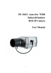
Full HD/ RealTime D&N Auto-Iris Outdoor IR Bullet IP Camera User’s Manual - 1 - 2013/09/03 version 1.1 CAUTION RISK OF ELECTRIC SHOCK. DO NOT OPEN! CAUTION : TO REDUCE THE RISK OF ELECTRICAL SHOCK, DO NOT OPEN COVERS (OR BACK). NO USER SERVICEABLE PARTS INSIDE. REFER SERVICING TO QUALIFIED SERVICE PERSONNEL. It is advised to read the Safety Precaution Guide through carefully before operating the product, prevent any possible danger. WARNING: This symbol is intended to alert the user to the presence of un-insulated “dangerous voltage”. CAUTION: This symbol is intended to alert the user to presence of important operating and maintenance (Servicing) instructions in the literature accompanying the appliance. Disposal of Old Electrical & Electronic Equipment (Applicable in the European Union and other European countries with separate collection systems).\ This symbol on the product or on its packaging indicates that this product shall not be treated as household waste. Instead it shall be handed over to the applicable collection point for the recycling of electrical and electronic equipment. By ensuring this product is disposed of correctly, you will help prevent potential negative consequences for the environment and human health, which could otherwise be caused by inappropriate waste handling of this product. The recycling of materials will help to conserve natural resources. For more detailed information about recycling of this product, please contact your local city office, your household waste disposal service or the shop where you purchased the product. The power cord is the main power connection. Therefore, constantly plug and unplug of the power cord might result in malfunction of the product. CE / FCC Mark. This apparatus is manufactured to comply with radio interference requirement. Do not install the product in an environment where the humidity is high. Unless the product is waterproof or weatherproof, otherwise it can cause the image quality to be poor. Do not drop the product or subject them to physical shocks. Except for vandal-proof or shockproof product, otherwise it will result malfunctions to occur. Never keep the product to direct strong light. It can damage the product. Do not spill liquid of any kind on the product. If it gets wet, wipe it dry immediately. Alcohol or beverage can contain minerals that corrode the electronic components. Do not expose to extreme temperatures. Use the product at temperatures within 0℃ ~ 50℃. - 2 - 2013/09/03 version 1.1 Table of Contents Product Feature ______________________________________________________________ - 5 Package Contents _____________________________________________________________ - 6 Physical Description ___________________________________________________________ - 6 Quick Installation _____________________________________________________________ - 9 Software Installation _________________________________________________________ - 14 - CHAPTER 1. System Configuration _______________________________________________ - 17 1.1 User Login________________________________________________________________ - 17 - CHAPTER 2. Live View Page ____________________________________________________ - 18 2.1 Video Type ________________________________________________________________ - 18 - 2.2 Protocol Type ______________________________________________________________ - 18 - 2.3 Utility ____________________________________________________________________ - 19 - 2.4 Light Status _______________________________________________________________ - 21 - CHAPTER 3. Client Setting______________________________________________________ - 22 3.1 Default Path _______________________________________________________________ - 22 - 3.2 Sound ____________________________________________________________________ - 23 - 3.3 Real Time OSD Setting _______________________________________________________ - 23 - 3.4 Stream Buffer Setting _______________________________________________________ - 23 - CHAPTER 4. Web Setting ______________________________________________________ - 24 4.1 System Setting _____________________________________________________________ - 25 - 4.2 Network Setting____________________________________________________________ - 30 - 4.3 Camera ___________________________________________________________________ - 36 - 4.4 Motion Detection __________________________________________________________ - 47 - 4.5 Event ____________________________________________________________________ - 49 - 4.6 Recording _________________________________________________________________ - 57 - 4.7 User Management __________________________________________________________ - 60 - 4.8 Storage Device _____________________________________________________________ - 62 - - 3 - 2013/09/03 version 1.1 Appendix A – Product FAQ _____________________________________________________ - 63 A. Web snapshot and recording doesn’t work in windows 7? ______________________________ - 63 B. After login camera, image page shows “connecting” message without showing image instead? - 63 C. Unable to see image because of ActiveX unsuccessful installation ________________________ - 64 D. Web page does not display correctly after firmware upgrade. ___________________________ - 67 E. Unable to open camera web page but Utility could search IP camera information under direct connection between PC and IP camera. _____________________________________________ - 69 - Appendix B – 3GPP on iPhone __________________________________________________ - 72 Appendix C – 3GPP on Android _________________________________________________ - 75 Appendix D – Specifications ____________________________________________________ - 78 - - 4 - 2013/09/03 version 1.1 Product Feature 2 Megapixel image; resolution is up 1920x1080 (3 Megapixel model resolution can reach 2048x1536). Support True WDR image processing. (For 3 Megapixel model) Support H.264 / MJPEG codec, video quality is adjustable, video type can be divided into Profile 1、Profile 2. Support Onvif version 2.3. Support G.711 codec, two ways audio is supported. Support high performance network transmission algorism, provide low-latency video and audio stream. Support event and schedule recording. Support motion detection; detection area and sensitivity are adjustable. Video stream bit rate, frame rate and resolution are adjustable. Support user management and password protect in order to provide the highest security. Support Micro SD Card for pre-event and post-event recording , schedule recording ,network disconnect recordin. Support remote setup, live view, recording, snapshot, ftp and firmware upgrade by web page or bundled software. Provide Utility for searching and network setting up supportive device in LAN. Network protocol supported: HTTP, UPnP, DNS, DDNS, RTSP, RTP, RTCP, RTSP over HTTP, TCP/IP, UDP/IP, ICMP, DHCP, PPPoE, FTP, NTP, SMTP, Bonjour, Multi-Casting. Support auto re-connecting after network or power shortage. Free bundle 64 channel surveillance software. Support maximum 64 channels live view and 16 channels playback simultaneously. - 5 - 2013/09/03 version 1.1 Package Contents IP Camera Quick Guide Intstallation CD Power Adaptor Ethernet Cable Physical Description Side Panel Description Video Out Slot for video out connector. User can find a BNC connector in product package. RESET When system is frozen, please press the reset button and keep it depressed for 5 seconds, after the power light is blinking, then release the reset button, the system will finish rebooting procedure in one minute. When the power light is on; the device is booted up successfully. Micro SD Support Micro SD card, the maximal capacity could be up to 32 GB. Device doesn’t support Micro SD hot swapping, please reboot system after insert or remove Micro SD card. IR LED Switch Three adjustable IR LED irradiate distance of 15 m (L), 25 m (M), 40 m (H). - 6 - 2013/09/03 version 1.1 NTSC/ PAL Switch Please switch video out source to NTSC or PAL at pin 1. Switch right for PAL video output; switch left for NTSC video output. NTSC PAL ● 1 Exterior View Power Connector Connect to 12V DC/1A power adapter. Ethernet Connect to Ethernet network. Alarm In/Out To connect external alarm I/O devices, please refer to below for Alarm I/O pin definition. GND Sensor IN ALR N.O ALR COM GND: ground wire. Sensor IN: connect to alarm in device. ALR N.O: connect to N.O(normal open) alarm out device. ALR COM: connect point that corresponds to alarm in. - 7 - 2013/09/03 version 1.1 Line-In (Pink) Slot for audio in connector. Line-Out (Green) Slot for audio out connector. RS485 The function is retained, pin defined as follows: D+ D- - 8 - 2013/09/03 version 1.1 Quick Installation Hardware Installation Basic Connection (1) Connect the 12V DC adaptor to the power jack of the IP camera. (2) Use Ethernet cable to make connection from the Ethernet 10/100 RJ45 socket of IP camera to the PC. - 9 - 2013/09/03 version 1.1 Network Setting After completing the basic hardware connection, make sure that the PC and the IP camera IP address are both in the same network segment. Example: Setup preset IP camera IP to 192.168.100.100 and configure your PC IP address as the figure description below. Setup format: IP Address:192.168.100.xxx Subnet Mask:255.255.255.0 Default Gateway:192.168.100.1 ※Note xxx address ranges from 1~254, please avoid using “100” which has been used by IP camera. Utility (1) Please install Utility from the product CD. (Please refer to chapter 3.3.1 for installation procedures.) (2) Start Utility. (3) After starting Utility, the program will automatically search and display supportive devices in local LAN. - 10 - 2013/09/03 version 1.1 (4) Choose which device you would like to access, the default IP address on the device is 192.168.100.100 (5) Double click on the IP address, will automatically open the selected device web image. (6) Please select on the device you would like to modify its setting and click “Modify”. Please fill in username and password. (Default username and password is admin/ admin) User can manually modify system setting: host name ,connection type , IP address ,and web port. Please click “Save” button before complete change. Utility provides firmware upgrade, please click on firmware upgrade checkbox, and select new firmware (.img) in pop-up window. System will automatically start firmware upgrade. (7) Click “Scan” to refresh searching supportive devices in local LAN. (8) If there is no DHCP server in local LAN, Utility can automatically assign IP address for connected network device. When Utility searches network device which IP address is - 11 - 2013/09/03 version 1.1 192.168.100.100 in LAN, system will automatically assign an IP address of which is the same network segment as client PC. To enable this function, please “Enable” on Auto Assign IP item. Please notice that DO NOT enable this function when there is already a DHCP server in LAN in case of IP conflict issues. (9) The same models firmware can be upgraded together through utility. Device Login Once you have logged in, you will see a pop-up information bar requiring your attention for installing ActiveX Control, use mouse right click to install ActiveX control. (1) Device default ID and password is admin/admin. Key in default ID and passwords when log-in. (2) Once you have logged in the first time, you will see a pop-up information bar requiring your attention for installing ActiveX Control, use mouse right click ”allow” to install ActiveX control. - 12 - 2013/09/03 version 1.1 (3) Once Active X installation complete, you will see the live viewing page. - 13 - 2013/09/03 version 1.1 Software Installation Please install following software from installation CD. Install Utility (1) Click Install Utility Tool (2) Click Next. - 14 - 2013/09/03 version 1.1 (3) Select Installation Folder. (4) Confirm Installation, please click Next. - 15 - 2013/09/03 version 1.1 (5) Installation complete, please click Close to exit. Recommended Computer Equipment CPU RAM Audio Card Operation System Browser Intel® Core 2 Due E7200 or above 1GB or above Needed Windows 2000, Windows XP SP2 and above, Windows Vista, Windows 7 IE6 SP2 and above - 16 - 2013/09/03 version 1.1 CHAPTER 1. System Configuration 1.1 User Login One minute after the device is powered on, please start Utility. The program will automatically search and display supportive devices in local LAN. Please click on the device you would like to access, and then enter login page of the device. Login device with default username and password: admin / admin. - 17 - 2013/09/03 version 1.1 CHAPTER 2. Live View Page 2.1 Video Type Video type can be divided into Profile 1、Profile 2. ※NOTE: Every single profile can be configured the video stream compression, resolution, frame rate, and bitrate. 2.2 Protocol Type Select image streaming transmission protocol. RTSP/ TCP Choose this item while the network is under low bandwidth. Video and audio streaming transmits through network TCP layer. - 18 - 2013/09/03 version 1.1 RTSP/ UDP Choose this item to get smooth live streaming. Video and audio streaming transmits through network UDP layer. ※NOTE: (1) When the network environment is not in LAN, please choose RTSP/TCP protocol type to obtain image. (2) RTSP / UDP protocol is not applicable for different network segments. RTSP over HTTP Video and audio streaming transmits through network TCP layer via HTTP port. 2.3 Utility Zoom In Click on the button to zoom in image. Image can zoom 8 times for maximum. To return back to normal image size, please click on zoom out button. Zoom Out Click on the button to zoom out image. The button has no effect when the image has back to original size. Stretch When image resolution greater than 720x480, click on the icon to adjust image size to 720x480. To return back original size, please click on the button again. Full Screen Click on the button or double click on the image, the full screen mode will be activated. Double click on the image can return to standard mode. Snapshot Click on the button, the image will be snapshoot, all image taken will be stored in default path., regarding the default path, please see chapter 3.1 (Client setting) - 19 - 2013/09/03 version 1.1 Recording Click on the button to start recording. Record file will be stored in default path. Regarding the default path, please see chapter3.1 (Client setting). Recording file is cut every 5 minutes; when the remaining space is less than 1GB or system setting is changed, recording will automatically stop. Stop Recording Click on the button to stop recording. Audio Click on the button to play audio; click again to stop playing. Broadcast Click on the button to start broadcast, click again to stop broadcasting. ※NOTE: The signal means not enable, when click on button (such as audio, broadcast). the signal will disappear and the button icon will be shown as , it means enable. (1) Direction Control Control the angles and direction of camera, with up, down, left, right, up left, up right, down left, and down right. Press a direction button; camera will rotate in this direction until releasing the button. The middle button is for back to home. - 20 - 2013/09/03 version 1.1 2.4 Light Status The lights from left to right are recording, audio and broadcast function status. (1) (2) (3) (1) Recording Status It is off by default, click on recording button, light will keep flashing; click on stop recording button, light will be off. (2) Audio Status It is off by default; click on audio button to enable audio function, light will keep flashing; click on the audio button again, light will be off. (3) Boradcast Status It is off by default; click on broadcast button to enable broadcast function, light will keep flashing; click on the broadcast button again, light will be off. - 21 - 2013/09/03 version 1.1 CHAPTER 3. Client Setting 3.1 Default Path Recording Select to change saving path of web recording files. Default is at “My Documents/(MAC address)”. Snapshot Select to change saving path of web snapshot files. Default is at “My Documents/(MAC address)”. Prefix Configuring prefix file name of the video files. Suffix Configuring the video file name format. - 22 - 2013/09/03 version 1.1 Date style: (prefix file name)(yyyy)-(mm)-(dd)-(five random number). Time style: (prefix file name)(yyyy)-(mm)-(dd)-(hh)-(mm)-(ss)-(four random number). 3.2 Sound Sound Recording Enable audio function while recording. 3.3 Real Time OSD Setting Display Items Select frame rate on video: frame rate per sec displayed on video image. Color Select OSD font color: White, Black, Red, Green, Blue, Yellow, Cyan, and Magenta Position Select placement for OSD: Top-Left, Top-Right, Bottom-Left and Bottom-Right. Please note that when choose the position as Top-Right, the real time OSD may cover recording OSD Background Color Select OSD background color: White, Black, and Transparency 3.4 Stream Buffer Setting Status Enable to turn on buffer function when viewing real time web pages, to increase smooth condition and stability Stream Buffer Time Configuring the buffer time of live viewing in web (default value is 300ms), video will a bit delay while stream buffer time enable, the higher value, the longer delay, the more smooth of video streaming. - 23 - 2013/09/03 version 1.1 CHAPTER 4. Web Setting Click on Setting” on the top right corner of the web page to configure the device, click on “LiveView” to return back to live view image. Setup - 24 - 2013/09/03 version 1.1 4.1 System Setting 4.1.1. Information This page will display the device status information, string field displayed information includes the configuration of the system, Ethernet, PPPoE, WebPort, DDNS. - 25 - 2013/09/03 version 1.1 4.1.2. Advanced Setting System Setting Firmware Upgrade To perform firmware upgrade, click on firmware upgrade button. Choose new firmware file, *.img, and click “Upgrade” button. System will automatically perform firmware upgrade. The whole process may take about 5 minutes to complete. DO NOT power off device during firmware upgrade in case system malfunction occur. ※NOTE:After the firmware upgrade, the settings will revert to the default state, by the option "Network" or "Daylight Saving Time" to choose whether to retain this setting after the firmware upgrade. Reboot Click on the button to reboot the device. Factory Default Click on the button to reset the device back to factory default settings. Configuration Setting Configuration Download Click the "Download" button to download the camera profiles. - 26 - 2013/09/03 version 1.1 ※NOTE:Download the profiles, by the "Network" or "Daylight Saving Time" option to select in the configuration file download, the server-side to retain the settings, do not download with configure profiles. Configuration Upgrade Click on the Upgrade button, you can upload a profile update existing equipment setting. 4.1.3. Time Setting Time Setting Time Zone Define time zone of current area. Keep current date and time Keep camera current date and time. Synchronize with computer time Enable to synchronize camera system time as client PC time. Manual ◎ Date: Fill in system date, the format should be: yyyy/mm/dd. ◎ Time: Fill in system time, the format should be: hh:mm:ss (24-hour clock). - 27 - 2013/09/03 version 1.1 Automatic ◎ NTP Server Fill in NTP server address. User can choose any one of below public NTP servers to use. time.stdtime.gov.tw asia.pool.ntp.org tw.pool.ntp.org us.pool.ntp.org europe.pool.ntp.org oceania.pool.ntp.org south-america.pool.ntp.org ◎ Updating interval Enable to synchronize time with NTP server every hour. 4.1.4. DST (Daylight Saving Time) Daylight Saving Time DST Enable this item to activate day light saving function. Start Date Fill in the start date of DST, the format should be: mm/dd. Start Time Fill in the start time of DST, the format should be: mm/dd. End Date Fill in the end date of DST, the format should be: mm/dd. - 28 - 2013/09/03 version 1.1 End Time Fill in the end time of DST, the format should be: mm/dd. 4.1.5. Log Log is the complete operation record of IP camera. If any trouble of IP camera, users can review and check it to find the failure root cause. Remote Log Enable remote log, all the log file can be saved in log server by internet. Current Log The IP camera log file record since boot. - 29 - 2013/09/03 version 1.1 4.2 Network Setting 4.2.1. Basic LAN DHCP Click on enable to activate DHCP; the device will get IP address from DHCP server. Static IP Manually set the IP address for the device. ◎ IP Address Fill in IP address for the device ◎ Subnet Mask Fill in a subnet mask of the device, If IP address of this device is changed, adjust the subnet mask accordingly. ◎ Gateway Fill in IP address of the gateway (the router). ◎ Primary DNS Define the primary DNS server IP address. This is used for identifying this device by name instead of IP address. ◎ Secondary DNS The IP address of the secondary DNS server; it will be used once the primary DNS server fails. - 30 - 2013/09/03 version 1.1 PPPoE Connect the device to internet by PPPoE through ISP. User Name Fill in the user name of the ISP account. Password Fill the password of the ISP account. Authentication Select the ISP PPPoE connection authentication, RAP or CHAP,before PPPoE connection. ※NOTE: CHAP authentication has encryption function, will be more secure than PAP; however, most of internet service provider prefer PAP authentication, will be by default PAP. 4.2.2. RTSP Live view the video of IP camera by VLC or QuickTime. Select streaming by using RTSP command. Live view Profile 1 video by keying in rtsp://IP Address/stream.sdp1 Live view Profile 2 video by keying in rtsp://IP Address/stream.sdp2 - 31 - 2013/09/03 version 1.1 4.2.3. Service DDNS Setting DDNS Enable this item to activate DDNS function. Server Select DDNS service system: dyndns.org or dhs.org, please access the DDNS websites below to apply for DDNS service. http://www.dyndns.com http://www.dhs.org Host Name Host name that user register for the device in DDNS website. User Name Username that user register in DDNS website. Password Password that user register in DDNS website - 32 - 2013/09/03 version 1.1 UPnP Setting Define the host name name. Enable this function to open UPnP service. Device can be found in “My network places 4.2.4. HTTP Web Port Setup device web port number, default is 80. To change to another port number, take 8080 for instance, set hyperlink format as below: http://192.168.100.100:8080 Do not duplicate web port with advanced ports. Recommended setting range is from 1000 to 65535. HTTPS Setting Select “Enable” to open the HTTPS protocol. Web connection is mandatory to HTTPS protocol. Default port is 443. Connection applying HTTPS protocol, the connection address is as follows: https://IP address When modifying a non-443 HTTPS port number, please add the port number to the connection address field, address format as shown below: https:// IP address: port number - 33 - 2013/09/03 version 1.1 Create and install certificate method Create and install SSL certification in IP camera when HTTPS activate, two methods for options: Create self-signed certificate manually Create certificate request and install 4.2.5. IP Address Filter - 34 - 2013/09/03 version 1.1 IP Filter Setting Filter IP addresses and select to receive or refuse requirements from IP IP Filter Type allow : Allow all the IP addresses connect to the device IP Filter Type deny : Deny all the IP addresses connect to the device, at least reserve 1set IP address to enable the function. Add IP Filter Rule : Fill in allowed or filtered IP address or IP segments - 35 - 2013/09/03 version 1.1 4.3 Camera 4.3.1. Basic Video Setting Video streaming is defined by profile 1 and 2,two streaming. Stream profile name: Configure every streaming name, which will be displayed on video type in Web UI for selections. Compression: Configure video compression, H.264 and MJPEG. Resolution: For configuring video resolution, the higher the resolution, the better image quality, the bigger image size, the available resolution listed as below H.264 & MJPEG 392 x 192 320 x 240 640 x 480 720 x 480 - 36 - 2013/09/03 version 1.1 1280 x 720 1280 x 960 1280 x 1024 1920 x 1080 2048 x 1536 This resolution is only supported 3 megapixel model ※NOTE: Note: Stream 2 is fixed by default up to resolution720x480 for better video quality. Frame rate: Video frame rater per second, the higher frame rate, the smoother video image; vice versa. If bitrate is configured with 4M, H.264 compression under every resolution, the frame rate can support up to 30fps. MJPEG compression depending on resolutions and video quality, the higher it is, the lower frame rate. For different image network environment, format and resolution frame rate of camera may be different. Above mentioned is for user reference only. ※NOTE: 2048 x1536 resolution is only 20 frame rate per second due to IP camera Performance. Video quality: ◎ VBR mode: transmit video streaming with float bit rate depending on video environment complexity. Five video quality options: Bad、Medium、Standard、 Good、Excellent; As table below, the higher video quality, the higher throughput Video Quality Throughput Bad 1~2 Mbits Medium 2~3 Mbits Standard 3~4 Mbits Good 6~7 Mbits Excellent 9~11Mbits ※NOTE: The throughput performance above table is for reference only, it is testing under compression H.264 and resolution 1920x1080. Bitrate throughput will be different depending on VBR mode for environment complexity. ◎ CBR mode : transmit stream with constant bit rate. ◎ Bitrate : Bit rate for image stream, the higher the value, the more delicate the image is. - 37 - 2013/09/03 version 1.1 Audio Mode Settings Duplex Mode : Select full duplex or half duplex mode, it’s full duplex by default. Please select duplex mode depending on the environment. Half duplex mode can be configured to avoid echo occurs; however, it cannot support two way audio simultaneously, it only can be one way audio prior to the other way audio. Audio In Settings Audio Source: Select audio source, Line-in or Microphone. (1) Line-in: Select the audio source with linear-level receive audio devices, such as amplifiers devices. (2) Microphone: Select built-in microphone for audio source. Audio Volume : Select the volume of the audio source. (1) When Audio source is Line-in, the volume range is 0~10, when number goes high, the volume goes high; vice versa. (2) When Audio source is microphone, the volume range is 0~1. Audio type: System provides G.711μ-law audio format, μ-law is used primarily in North America. G.711 is an ITU-T standard for audio companding. It is primarily used in telephony. Sampling frequency 8 kHz and 64 kbit/s bitrate - 38 - 2013/09/03 version 1.1 Video Out Settings Enable video output Video output through BNC connector of IP camera to displayer Video output type Select the video display mode for NTSC or PAL format ◎ HW : According to the hardware switch to adjust the video output for NTSC or PAL format. ◎ NTSC : Adjust the video display format to NTSC. ◎ PAL : Adjust the video display format to PAL. - 39 - 2013/09/03 version 1.1 4.3.2. Image Basic Setting - 40 - 2013/09/03 version 1.1 Image Color Select image color in color or mono. Brightness Adjust image brightness parameter; the higher the value, the brighter the image. Saturation Adjust image saturation parameter; the higher the value, the more saturate the image. Contrast Adjust image contrast parameter; the higher the value, the higher the contrast of image. Hue Adjust video hue parameter, the smaller the value, the bluer the video is; reversely, the higher the value is, the redder the video is. Flip Enable to flip over image. System needs to reconnect stream to refresh preview window. Before clicking save button, system would not reconnect the stream. Mirror Enable to mirror image. System needs to reconnect stream to refresh preview window. Before clicking save button, system would not reconnect the stream. Advanced Setting WDR (Wide dynamic range) This feature is only supported 3 megapixel model. When the WDR application is enable the ISP can adjust the parameter of Gamma to add reduce the brightness .The Camera wide dynamic level range from 0~10,set the higher value, the greater of wide dynamic amplitude, set the smaller value, the smaller of wide dynamic amplitude - 41 - 2013/09/03 version 1.1 ※NOTE: Pictures for reference only, please select WDR level according to the environment. White Balance Choose Current White Balance Way; default setting is Auto White Balance。 ◎ AWB (Color Temperature 2800~6500K) ◎ ATW (Color Temperature 2500~8000K) ◎ Outdoor (Color Temperature 6500K) ◎ Indoor (Color Temperature 3200K) ◎ Lamp (Color Temperature 2800K) BLC (Backlight Compensation) Select BLC level, low, mid, or high when back light is too strong. The higher of BLC level, the higher of video light compensation. Please refer to below pictures by each BLC level. ※NOTE: Pictures for reference only, please select BLC level according to the environment. - 42 - 2013/09/03 version 1.1 Day / Night Setting Day/ Night is set for controlling ICR switching, it’s auto by default. Day / Night ◎ Auto: ICR switch automatically depends on the illumination of scene difference. ICR switches to night mode, live image switches to mono color. ◎ Day: ICR switches to day mode, live image switches to color mode. ◎ Night: ICR switches to night mode, live image switches to B/W mode. ◎ Sensor: Sensor can trigger ICR switch through external signals, two types of alarm-in mode: open or close. ※NOTE: Open stands for alarm IO: ground (G) and digital in (IN) is open, video image is black and white; When alarm IO ground (G) and digital in (IN) is close, video image is colored. Close stands for ground (G) and digital in (IN) is open, video image is colored; When alarm IO ground (G) and digital in (IN) is close, video image is black and white. Ext IR (External IR) ◎ IR illuminator: connect to alarm out (N.O, COM) and select normal open (NO) or normal close(NC) to enable external alarm device. Exposure Setting - 43 - 2013/09/03 version 1.1 IRIS: select auto or manual ◎ Auto: Auto-iris can automatically adjust the amount of light entering with a mechanism to have a camera stay in an optimal light level. ◎ Fix Max: Iris fixed to the maximum. Shutter Speed : select auto or manual, shutter speed can be configured 1/4~1/10000, the higher speed, the less exposure, the darker video image; vice versa. ◎ Auto: auto mode is the range 1/30~1/120 by default to avoid flicker. ◎ Manual: manual mode can be configured the shutter speed range manually. In each speed range, shutter speed value will be controlled during the maximum and minimum value. Gain Control Gain control setting is current gain range, from 0~24db, can be adjusted based on Day and Night. Ev (Exposure Compensation Value ) Select Exposure compensation value to control the video image brighter or darker, range from -2~+2, the higher value, the brighter video image, the lower value, the darker video image Power Line Select the power line 50Hz or 60Hz to avoid flicker on video image, which is caused by electric power frequency - 44 - 2013/09/03 version 1.1 4.3.3. OSD (On Screen Display) Recording OSD Setting Display OSD on record files. Display Enable to display system date and time on recording OSD. Title Enter desired title and select Enable to display title on the recorded video image. Maximal word length is 16 characters. - 45 - 2013/09/03 version 1.1 4.3.4. PA (Privacy Area) Video Private area setting in video image, left click to set the area range with 3 areas, each by red, green, and blue for identification. Delete Click the button to delete privacy of chosen rectangle color. Clear All Click the button to clear all privacy areas. Privacy Area Setting. Status Enable status of privacy area setting ※NOTE:Privacy setting area is related to image resolution, to avoid position inaccuracy, please set up privacy rectangle after setting resolution. - 46 - 2013/09/03 version 1.1 4.4 Motion Detection 4.4.1. Basic Motion Detection Enable motion detection, the relate alarm notice will be automatically triggered when IP camera detect motion in the specifying area. Event trigger time can be configured at least 1 second. After event trigger relate actions completed, IP camera still detected motion, the event will be triggered repeatedly. Please click Event button to do relate configuration. Motion detection area setting in video image, left click to set the area range with 3 areas, each by red, green, and blue for identification. Video Privacy Rect. Select rectangle color and select range on image to define privacy area. - 47 - 2013/09/03 version 1.1 Select All Click the button to enable full area detection. Delete Click the button to delete privacy of chosen rectangle color. Clear All Click the button to clear all privacy areas. Motion Detection Setting Status Enable this item to activate motion detection. Name Configure the name of 3 areas by each for identification. Sensitivity Configure sensitivity of motion detection, range from 0~100, the higher value, the higher sensitivity; vice versa. Threshold Configure threshold of motion detection, range from 0~100, the higher value, the more difficult to trigger event; vice versa. - 48 - 2013/09/03 version 1.1 4.5 Event 4.5.1. Basic IP camera provide three types event alarm: Motion detection、Periodically、Digital input. Through event setting, event trigger alarm can be delivered by SD card, email, and FTP. Event Setting ◎ Name : Display event name ◎ Status: Enable each event type status and will enable relate rigger actions. The function is the same as “enable this event” ◎ Schedule : event trigger schedule ◎ Trigger : event trigger type - 49 - 2013/09/03 version 1.1 ◎ Add : Select event type and add it in event trigger ◎ Delete : Select event type and delete event trigger Event Setting ◎ Event name : Configure event name with 40 bits maximum ◎ Enable this event : Enable relate event-trigger actions ◎ Detect next event after : Configure event-trigger duration from previous to next event, only support motion detection and digital input event-trigger type ※NOTE: A complete process of event trigger alarm depending on video successful access. The next event trigger alarm will be enabled after the previous event video successful access. Trigger Event-trigger type: Motion detection, Periodically, Digital input ◎ Video motion detection : Select M1, M2, or M3 of normal part to enable motion detection event trigger. M0 is Motion Area 1、M1 is Motion Area 2、M2 is Motion Area 3,Please configure motion detection setting before event trigger setting. ◎ Periodically Configure periodical event-trigger in one duration; duration is that event trigger every other 1 minute by default, it can configure 999 minutes the maximum. Event will automatically trigger periodically. - 50 - 2013/09/03 version 1.1 ◎ Digital input: Enable digital output (connect IP camera digital in port ) to trigger alarm by selecting Open or close ※NOTE: Open stands for ground (G) and digital in (IN) is open, when they touch together, it will trigger message transmission to digital output; Close stands for ground (G) and digital in (IN) is close, when they apart from each other, it will also trigger message transmission to digital output. Event Schedule Configure the schedule (date and time) to do event triggering ◎ Select all : Click to select all the schedule to do event-trigger alarm ◎ Clear all : Click to clear all the schedule to do event-trigger alarm Action - 51 - 2013/09/03 version 1.1 Configure relate actions after event-trigger, such as alarm out, SD card storage, FTP & Email transmission. ◎ Trigger digital output : alarm device is connected to IP camera I/O N.O and COM connector, ex: buzzers. ◎ AlarmOut_1: Enable AlarmOut_1 by selecting normal open (NO) or normal close (NC) to enable alarm device. ◎ Add Server : Configure email and FTP relate setting when event trigger alarm (refer to chapter 4.6.1 server setting) ◎ Add media: Configure recording time duration of each event when event trigger alarm ( refer to 4.6.1 Media Setting) ◎ ◎ ◎ ◎ Status : Enable status of each action Server : Display Server items Media : Select configured media items Extra parameter : Open Server items configuration page SD Please refer to chapter4.9 Storage Device FTP Setting Path : Fill in FTP site. If not filled, the default path is the root directory(“\”) - 52 - 2013/09/03 version 1.1 E-mail Setting Email To : fill e-mail address (five mails addresses the maximum) Subject : fill in e-mail subject Message : E-mail content Server Setting Select alarm transmissions method, FTP or SMTP, when event trigger alarm. ◎ Name : Display Server name ◎ Type : Display Server type, FTP or SMTP(E-mail). ◎ Address/Location : Display server address ◎ Add : Add FTP or SMTP server ◎ Delete : Delete FTP or SMTP server - 53 - 2013/09/03 version 1.1 Server Setting ◎ Server name : Fill in server name Server Type ◎ E-mail Sender email address : Fill in sender’s e-mail Address Server address : Fill SMTP Server address User name : Fill in sender’s email account Password: Fill in sender’s email password Server Port : Fill in SMTP Server Port, it is 25 by default. Security Mode : Select security mode SSL or TLS, it is none by default. - 54 - 2013/09/03 version 1.1 ◎ Test Selected server type Enable the item for testing email successful transmission. Email To : Fill in receiver’s e-mail address Subject : Fill in e-mail subject Message : Fill in e-mail content ◎ FTP Sender address : Fill in FTP server address Server Port: Fill in FTP Server Port, it is 21 by default. User name : Fill in FTP Server account Password: Fill in FTP Server password Passive mode: If FTP Server transmission method is passive, enable it for successful transmission. ◎ Test Selected server type Enable the item for testing email successful transmission. Path : Fill in server site. If not filled, the default path is the root directory - 55 - 2013/09/03 version 1.1 Media Setting Configure the media of alarm, IP camera provide event recording (pre-event and post-event) in current stage. ◎ ◎ ◎ ◎ Name : Display Media name Type : Display Media type,only pre-event and post-event recording (VideoClip) Add : Add Media function Delete : Delete Media function Media Setting ◎ Media name : Fill in Media name Video Type ◎ Video Clip : Enable video clip to provide pre-event and post-event recording video clip. Source : Select streaming source, only stream 1 (profile 1) available in current stage. Pre-event recording : Configure pre-event recording time,range from 0~5 seconds Maximun duration : Configure post-event recording time, range from 1~5 seconds File name format Perfix : Prefix can be configured on standard file name format. - 56 - 2013/09/03 version 1.1 4.6 Recording 4.6.1. Basic Recording settings Configure it for recording video by schedule and network failure, which are both saved in SD card. ◎ ◎ ◎ ◎ ◎ ◎ ◎ Name : Display recording video name Status : Enable relate recording actions, the same function as “Enable this Recording” Schedule : Display all recording enable schedule Source : Display video streaming source Destination: Display recording video storage destination, only saved in SD card. Add : Select recording video type and add it in recording settings. Test dest. : Enable the item for testing recording video successful transmission to destination ◎ Delete : Select recording video type and delete it in recording settings. Recording ◎ Recording name : configure recording name with 40 bits maximum. ◎ Enable this recording : enable relate event-trigger recordings. - 57 - 2013/09/03 version 1.1 Trigger Recording video by schedule and network failure, the files will be saved in SD card. ◎ Schedule Recording video by schedule configuration, the files will be saved in SD card ◎ Network fail Recording video by network failure, IP camera will start recording from 5 seconds before network failure. When network recovery, it will stop recording, and the files will be saved in SD card. ◎ Recording schedule Configure the schedule (date and time) to recording the video ◎ Select all :Click to select all the schedule to do video recording. ◎ Clear all : Click to clear all the schedule - 58 - 2013/09/03 version 1.1 File Format ◎ Destination Display recording video storage destination, only saved in SD card ◎ Max File length Video recording file length, range from 1~6 minutes ◎ Folder Format Folder of video recording format, Recording Name or Date And Time. Recording Name : Folder is named the same as recording name. EX: If Recording Name is configure “test”, the folder will be named “test”. Date And Time : Folder is named by date and time. The format is yyyy-mm-dd_hh. EX: Recording time is at 18:00 o’clock on June 21, 2013. The folder name will be 2013-06-21_18. ◎ File Name Format Recording file name format, Sequence or Date And Time Sequence: File is named by date and time. The format yyyy-mm-dd_hh_mm_ss_number, serial number will be added in the end of name. EX: Recording time is at 00secs, 25mins, 18:00 on June 21, 2013. The name will be 2013-06-21_18-25-00_0, the next file name will 2013-06-21_18-26-00_1. Date And Time : File is named by date and time. The format is yyyy-mm-dd_hh_mm_ss. Recording time is at 53secs, 04mins, 18:00 on June 21, 2013. The file name will be 2013-06-21-18-04-53 is file file be ※NOTE : Do not take off SD card from IP camera during recording in SD card to avoid SD card damage and SD card read defect. Please un-mount SD card prior to take off SD card from IP camera. (Refer to chapter 4.9.1) - 59 - 2013/09/03 version 1.1 4.7 User Management 4.7.1. Basic Change Password Enter the original password and new password, click on “change” button to finish password change. Password of operator and guest accounts are not changeable, if user wants to change the password of operator and guest accounts, please login as administrator, and delete operator or guest account, and create new accounts. Add User Enter username and password, select the user group level and click on “add” button. The maximal users can be set up to 15. The account name characters should follow the restrictions below: Enter user name and password; the characters can be Arabic alphabet 0~9, capitalized or non-capitalized English alphabet, and symbol“-”, “_”and “.”. The maximum inputs are 32 characters. English upper and lower case are seen as different character. Admin is unique. Admin can create operator and guest level users. Operator and guest level users have no right to add user. - 60 - 2013/09/03 version 1.1 User List List all users in the table. Click on “Delete” button to delete user. User Security Level System provides three levels users; please refer to below table for each level’s permission. User Level Administrator Operator View Live View Image ◎ ◎ ◎ Live View Broadcast Utility ◎ ◎ ◎ ◎ ◎ - 61 - Setting ◎ User Management ◎ 2013/09/03 version 1.1 4.8 Storage Device 4.8.1. Basic SD SD card shall be formatted by FAT32 before installing SD card to avoid detection failure. Total Capacity Display the total capacity of the backup device. Used Capacity Display the used space of the backup device. Remaining Capacity Display free space of the backup device. Storage File List Use the browser to open SD Card file list. Secure Digital Status IP camera provide mount and un-mount function for SD card. ◎ Mount : If IP camera cannot detect SD card, please mount SD card to connect to IP camera. ◎ Un-Mount : If taking off SD card is needed during recording, please un-mount SD card prior to take off SD card from IP camera. - 62 - 2013/09/03 version 1.1 Appendix A – Product FAQ A. Web snapshot and recording doesn’t work in windows 7? Due to windows authority limitation, please use following procedure to fix this problem. Right click on “Internet Explorer” icon and choose “Run as administrator”. All operations on camera web page can work normally then. B. After login camera, image page shows “connecting” message without showing image instead? Please check following settings to fix. Local Area Network (LAN) 1. Has FFDShow decoder software installed already? (1) The very first time connecting to camera web page, system would ask to install FFDShow. Please install with default settings. (2) Install FFDShow from product installation CD. Internet (WAN) 2. Please check upload/download bandwidth and router setting. (1) Insufficient bandwidth may cause image unable to connect. Please check the networking bandwidth with your network service provider. Change IP camera Bitrate and FPS to moderate value to transfer. (2) Router firewall may block connecting protocols. Please make sure Web and RTSP ports are added into port forwarding or NAT service of router. - 63 - 2013/09/03 version 1.1 C. Unable to see image because of ActiveX unsuccessful installation 1. Disable memory protection of IE8, WinXP (1) Open an IE window and click “Tools”→”Internet Options”. (2) Click on “Advanced” tag and disable “Enable memory protection to help mitigate online attacks" option”. Click “Apply” to exit. - 64 - 2013/09/03 version 1.1 (3) Restart IE to affect setting. (4) Reconnect IP camera web page, ActiveX control plug-in is ready to install. 2. Disable IE protected mode of IE8, Win7 (1) Open an IE window and click “Tools”→”Internet Options”. (2) Click on “Security” tag, disable “Enable Protected Mode (requires restarting Internet Explorer)”. - 65 - 2013/09/03 version 1.1 (3) Click on “Advanced” tag and disable “Enable memory protection to help mitigate online attacks" option”. Click “Apply” to exit. (4) Restart IE to affect setting. (5) Reconnect IP camera web page, ActiveX control plug-in is ready to install. - 66 - 2013/09/03 version 1.1 D. Web page does not display correctly after firmware upgrade. This problem may cause by temporary internet cache, please follow procedures to fix. (1) Open an IE window and click “Tools”→”Internet Options”. (2) Click “General” tag and click “Delete…” in browsing history field. - 67 - 2013/09/03 version 1.1 (3) Delete “Temporary Internet files” and “Cookies” both items. (4) Restart IE to affect setting. (5) Reconnect IP camera web page. - 68 - 2013/09/03 version 1.1 E. Unable to open camera web page but Utility could search IP camera information under direct connection between PC and IP camera. This problem may cause by following reasons: 1. Does PC and IP camera set in the same network segment? Please refer to “Setup” section of user manual. 2. Does proxy setting enable? (1) Open an IE window and click “Tools”→”Internet Options”. (2) Switch to “Connection” tag, and click “LAN settings”. - 69 - 2013/09/03 version 1.1 (3) Disable "Use a proxy server for your LAN", then click [OK] button. (4) Restart IE to affect setting. (5) Reconnect IP camera web page. ※ To connect IP camera without through proxy server in LAN, please follow procedures: (1) Click “Advanced”. - 70 - 2013/09/03 version 1.1 (2) Fill in “192.168 .*.*” in exceptions, then click “OK” to exit. (3) Restart IE to affect seeting. (4) Reconnect IP camera web page - 71 - 2013/09/03 version 1.1 Appendix B – 3GPP on iPhone ※ IP cameras provide free bundled APP for live viewing, the steps as follows: (3) Please click on the main screen of the App Store icon。 (2) Click on "Search" icon and search for『SecuCON Mobile』。 (3) Download and install it in your iphone (4) Click on - 72 - Mobile icon 2013/09/03 version 1.1 (5) Click on【+】button to add IP cameras (6) Configure IP address, port number (default 554), username, and password of IP camera and click on【Save】button - 73 - 2013/09/03 version 1.1 (7) Click on the configured IP camera (8) Live view IP camera ※NOTE: APP captures the 2nd stream of IP camera. For more smooth video quality, the suggested configuration is that the resolution is 640x480, bitrate 1M, and frame rate 30fps. - 74 - 2013/09/03 version 1.1 Appendix C – 3GPP on Android ※ IP cameras provide free bundled APP for live viewing, the steps as follows: (1) Please click on the main screen of the Android Market icon. (2) Click on "Search" icon and search for『SecuCON Mobile』。 (3) Download and install it in your iphone (4) Click on - 75 - Mobile icon 2013/09/03 version 1.1 (5) Click on【+】button to add IP cameras. (6) Configure IP address, port number (default 554), username, and password of IP camera and click on【Save】button. - 76 - 2013/09/03 version 1.1 (7) Click on the configured IP camera. (8) Live view IP camera. ※NOTE: APP captures the 2nd stream of IP camera. For more smooth video quality, the suggested configuration is that the resolution is 640x480, bitrate 1M, and frame rate 30fps. - 77 - 2013/09/03 version 1.1 Appendix D – Specifications Model No. Sensor RYK-IPBL100 RYK-IPBL200 RYK-IPBL300 1/2.7” Progressive 1/2.7” Progressive 1/2.8” SONY "Exmor" CMOS CMOS CMOS 1.3 Mega 2.0 Mega 3 Mega 1280 x 1024 1920 x 1080 2048 x 1536@20fps Resolution Picture Elements Frame Rates IMAGE LENS VIDEO AUDIO Shutter Speed Automatic, Manual (1/4 ~ 1/10000 sec) White Balance Automatic, Manual (2500 ~ 8000K) Minimum Illumination 0.5Lux @ F1.2 (Color), 0.01Lux @ F1.2 (B/W) Gain Control Auto, Manual (0~24db) Back Light Comp. Yes WDR No DNR 2D Noise Filter IR-Cut filter Removable Yes Day & Night Auto Lens Drive Type Vari-focal Lens, f=3.5~16mm, F/1.2 Mount Ø 14 mm Iris DC Drive IR Illumination Distance Max. 30M (IR Range Selectable) Video Compression H.264 & M-JPEG Video Streaming 3 Streaming Flip & Mirror Yes Privacy Mask 3 areas Motion Detection 3 areas Audio Compression G.711 2way Audio Yes Audio In/Out 1 x Line-In, 1 x Line-Out (3.5mm Phone Jack) Ethernet 10/100 Base T Ethernet (RJ-45) Protocol NETWORK Applications 1920 x 1080@30fps 30fps Yes HTTP, HTTPs, DHCP, PPPoE, DDNS, SMTP, FTP server, FTP client, NTP, Bonjour, QoS Password Protection Yes Live Viewing User 5 Wireless No Network Storage Auto, Manual (0~42db) NVR, NVR, SD Card Network Fail Recording, SD Card Schedule - 78 - 2013/09/03 version 1.1 Recordin GENERAL Live Viewing IE, , Vandal Proof No Weatherproof IP66 Heater / FAN Yes SD Card Slot Micro SD Card Slot Alarm 1 x DI, 1 x DO(Dry Contact) Power AC24V;DC12V /3A ; PoE 802.3 AT Operating Temp. -40°C ~ 50°C (-40°F to 122°F) Integrate Document CGI URL Command Video Output Composite Video Out (BNC) x 1 RS485 Interface Yes Dimension (W x H x D) 109 x 171.3 x 251.4 (mm) Weight 0.7(kg) Humidity 0% ~ 90% RH Certificate CE, FCC Mobile - 79 - 2013/09/03 version 1.1