1
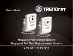
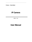
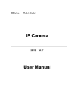
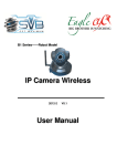
Network / IP Camera Module User’s Guide (Version 1.3) LNC IP Camera Module User’s Guide Preface Congratulations on your purchase of this product. Read this manual carefully and keep it in a safe place for any future reference. About this manual This user manual has been designed to help you make the most of your IP camera and its many features and functions. Information in this document has been carefully checked for accuracy; however, no guarantee is given to the correctness of the contents. The information in this document is subject to change without notice. Copyright © Copyright 2011 This manual contains proprietary information, protected by copyright. All rights reserved. Contact Information Leopard Imaging Inc. 1130 Cadillac CT Milpitas, CA 95035 Phone: (408) 263-0988 Fax: (408) 217-1960 Email: [email protected] Technical Support: [email protected] Web site: www.leopardimaging.com 2 LNC IP Camera Module User’s Guide Contents Introduction ................................................................................................................................... 4 Package contents ........................................................................................................................... 4 1. Product Introduction ............................................................................................................ 5 1.1 Product outline .................................................................................................................. 5 1.2 Key features ....................................................................................................................... 5 1.3 Technical Spec ................................................................................................................... 6 2. Product Views ........................................................................................................................ 7 2.1 User Interface .................................................................................................................... 7 2.2 Indicators ........................................................................................................................... 8 2.3 Product Dimensions .......................................................................................................... 8 3. System Installation ................................................................................................................ 9 3.1 Operating Environment ................................................................................................... 9 3.2 System installation ............................................................................................................ 9 4. Internet Explorer .................................................................................................................. 9 4.1 Preparation ........................................................................................................................ 9 4.2 Accessing the video preview ........................................................................................... 10 4.3 IE Interface Overview .................................................................................................... 12 4.4 Settings ............................................................................................................................. 13 I. Image Setting ............................................................................................................... 13 II. Video Setting ............................................................................................................... 18 III. Video Analytics ......................................................................................................... 24 IV. Audio Setting ............................................................................................................. 26 V. Time Setting ................................................................................................................ 27 VI. Network Setting ........................................................................................................ 28 VII. Alarm Setting ........................................................................................................... 30 VIII. RsPort ..................................................................................................................... 32 IX. Maintenance .............................................................................................................. 33 X. About Product ............................................................................................................ 35 5. FAQ ...................................................................................................................................... 36 5.1. Client software can not access the network video server ............................................. 36 5.2. The video server cannot be found by terminal configuration tool .............................. 36 Appendix ...................................................................................................................................... 37 A1. How to enable the UPnP in Windows XP....................................................................... 37 A2. Milestone XProtect ........................................................................................................... 37 3 LNC IP Camera Module User’s Guide Introduction This section covers unpacking your new IP camera Module, its key features, and basic technical information about the product. Refer to later chapters for information on setting up and configuring the product in more detail. Package contents The package should contain all the following contents. If anything is missing or appears damaged, contact your dealer immediately. 1. LNC IP Camera Module (1) 2. 12V DC Power Adapter (1) 3. User’s Guide (1) 4. Mounting bracket (1) 5. Certificate and Warranty Card (1) Optional Accessory: 1. Tripod Bracket 4 LNC IP Camera Module User’s Guide 1. Product Introduction 1.1 Product outline Leopard Imaging LNC IP camera is the next-generation IP Camera with different sensor boards from different manufacturers. It outputs full HD Video in H.264, MPEG-4, MJPEG and other video format at 30 frames per second, which makes clear images achievable even under high-contrast, low-light environment. The LNC IP Camera is ONVIF compliant and can be easily integrated into security systems. 1.2 Key features 1080P/720P Full HD video output at 30 frames per second Support single / dual / triple media streaming output Support face detection Support motion detection, alarm linkage Support image enhancement, low-light treatment Optional PoE support ONVIF Compliance Standard H.264, MPEG-4, MJPEG video compression format Standard G.711 audio compression format Support 1080P, 720P, D1 resolution Built-in Web Server, fully support monitor, configure and manage via IE Dynamic frame rate control, real-time audio and video on the Internet to ensure transmission Support the adjustment of image parameters 5 LNC IP Camera Module User’s Guide 1.3 Technical Spec 1080p Image Input Sensor Day/Night Active Pixels e-shoot Image Enhance Lens Image Process Resolution Format Frame Rate Video Analytics Motion Detection Face Detection Audio Encoding Network Protocols 720p HD CMOS Auto Switch (Optional Feature) About 200M About 100M 1/2 to 1/10,000 s Auto Gain, Auto Exposure, Auto White Balance Fix focus, IRIS support, C/CS mount lens suppot 1920x1080,1280x720,D1 H.264, MPEG-4, JPEG H264/MPEG-4: 30f/s 1280x720,D1 Support Support G.711 TCP/IP, ARP, ICMP, HTTP, FTP (client/server), SMTP, DHCP, DNS, NTP, RTP/RTCP Wireless Support (Optional WIFI Module) Protocol ONVIF Authentication IEEE802.1X UPnP protocol Support Zero configuration protocol Support Interfaces Network 10BASE-T/100BASE-TX (RJ-45) Serial Port RS-485 (PELCO D protocol) Extension Storage SD card x 1 Alarm In/Out x1 Input,x1 Output External Audio Input 3.5MM Audio Input Interface External Audio Output 3.5MM Audio Output Interface Work Environment Weight 106gram Dimensions 113mm(L)*58mm(W)*32mm(H) Power Supply PoE (Optional), DC12V Power Consuming <3w Temperature -20℃~ 45℃ Humidity 10% ~ 80% no condense Video Management Software on PC OS Microsoft Windows 98/2000/XP/Vista/Win7 Browser Internet Explorer6.0 or above Record Software Milestone XProtect (3 rd party software, see Appendix 2) 6 LNC IP Camera Module User’s Guide 2. Product Views Use the following illustrations to familiarize yourself with the camera and identify each of the parts. 2.1 User Interface Figure 1: User Interface Interface Description LAN RJ45 LAN Connector Power Power Indicator DC 12V Power Input DC 12V/1A A out Audio output A in Audio input SD Card SD card slot Mini USB USB interface AUTO IRIS Auto iris lens contact, (Supports DC lens) ANT Wireless LAN interface 7 LNC IP Camera Module User’s Guide ALM out Alarm output ALM in Alarm input (low level) GND Ground RS485 RS485 control, left RS485(-), right RS485(+) . PTZ decoder can be connected to support multiple PTZ protocol. 2.2 Indicators The following table provides a description of each of the LED indicators: Power Indicator Power LED RJ45 TX/RX Indicator LAN Green RJ45 LINK Indicator LAN Orange 2.3 Product Dimensions (mm) 8 LNC IP Camera Module User’s Guide 3. System Installation 3.1 Operating Environment The IP Camera video streaming can be viewed on a PC with Windows XP (or higher) OS via the TCP/IP protocol. 3.2 System installation 1. Connect the IP Camera to the network or directly to PC via Ethernet cable. 2. Connect the 12V DC Power to the camera. 3. Normally the “link” indicator (Orange) of the RJ45 connector will light up in about 5 seconds while the data indicator (Green) will start blinking. This indicates that the network connection of the IP Camera has been set up. 4. Internet Explorer 4.1 Preparation 1. To connect the Leopard IP Camera directly to a PC, the PC must be configured to be a DHCP server. Below are the steps to set up this connection: Make sure the PC has the correct Operating system with UPnP installed and is connected to the IP Camera correctly. (Refer to Section 3) Connect the external power adapter. The DHCP server will assign an IP to the IP Camera and the camera will show up as a UPnP device. Refer to the UPnP device for the IP address of the camera or directly open the device; Enter the User name and password to access the preview of the IP Camera 9 LNC IP Camera Module User’s Guide Figure 2: Connecting to Network 2. Connecting the IP Camera to a network: To connect the IP Camera to a network via a Router: Make sure the client PC with correct OS is also connected to the same network. Connect the external Power to the IP Camera. The router will assign an IP address to the IP Camera. The IP Camera will show up on the PC as a UPnP device. 3. When browsing the IP Camera on the IE for the first time, please refer to Appendix 2 of the file Set up and Re-programming to install Add-on to get the IE interface. 10 LNC IP Camera Module User’s Guide 4.2 Accessing the video preview To access the video preview, please follow the steps below: 1. Click “UPnP”, and you will get the following interface: 2. Figure 3: Login Interface In order to complete the installation of the Control successfully through the browser, the version of IE must be upgraded to 6.0 or above. 3. Enter user Name: admin 4. Enter password: admin 5. Click “OK”. You will the get to the video preview as show below: Figure 4: Live Video Interfaces 11 LNC IP Camera Module User’s Guide 4.3 IE Interface Overview The Window displays real-time video images, as shown in Figure 4. The Client interface includes: Live video Preview. Navigation interface on the left part of the webpage, shown in Figure 5. These Interfaces will be introduced in detail in the following sections. Figure 5: Navigation Interface PTZ interface on the right of the webpage. 12 LNC IP Camera Module User’s Guide Figure 6: PTZ Interface Recording and Snapshot Start recording: After click “Start recording”, video will be saved to your PC; Click again, video recording will stop. Snapshot: After click “Snapshot”, you will capture an image. Figure 7: Recording and Snapshot 4.4 Settings I. Image Setting Figure 8: Image Setting 13 LNC IP Camera Module User’s Guide Basic Adjustment Figure 9: Basic Adjustment Brightness: Scroll bar to control brightness. (value ranges from 1 to 255) Contrast: Scroll bar to control contrast. (value ranges from 1 to 255) Saturation: Scroll bar to control saturation. (value ranges from 1 to 255) Sharpness: Scroll bar to control sharpness. (value ranges from 1 to 255) Exposure Control Auto Exposure Figure 10: Auto Exposure 14 LNC IP Camera Module User’s Guide o Minimal Framerate: Use the pull-down list to choose the minimal framerate. 30 25 15 8 1 o Max Gain: 1 ~ 10 o Auto Iris: ON / OFF o Flicker Control: Use the pull-down list to choose the anti-flicker frequency 60hz flicker 50hz flicker Manual Exposure: Figure 11: Manual Exposure o Exposure Time o Gain: 1 ~ 10 15 LNC IP Camera Module User’s Guide White Balance: ON / OFF Figure 12: Auto White Balance Day Night Mode Setting Figure 13: Auto Day-night mode shift Min Brightness(1- 45): when the brightness is lower than min, night mode will open Max Brightness(1- 45): when the brightness is higher than max, day mode will open 16 LNC IP Camera Module User’s Guide WDR Figure 14: WDR None Low Global Enhancement Medium Global Enhancement High Global Enhancement Low Local Enhancement Medium Local Enhancement High Local Enhancement 17 LNC IP Camera Module User’s Guide Noise Filter Figure 15: Noise Filter 2D Filter: ON / OFF 3D Filter: ON / OFF II. Video Setting Figure 16: Video Setting 18 LNC IP Camera Module User’s Guide Video Combo Main stream Figure 17: Main stream o Resolution: 1080p: 1920x1080 720p: 1280x720 SXVGA:1280x960 D1: 720x480 o Framerate: 30 25 16 8 1 o Image Quality: High Medium High Medium Medium Low Low Very Low 19 LNC IP Camera Module User’s Guide o Rate Control OFF VBR CBR o Max Bit-rate 5M 4M 3M 2M 1M Sub stream Figure 18: Sub stream o Enable Sub stream: After Enable Sub stream, go to “Live video” and click the stream name to refresh it, you will get two steam names. Click “All streams”, you will get two live videos on the interface. 20 LNC IP Camera Module User’s Guide o Resolution: 720p:1280x720 D1: 720x480 VGA: 640x352 QVGA: 320x192 o Framerate: 30 25 16 8 1 o Image Quality: High Medium High Medium Medium Low Low Very Low o Rate Control OFF VBR CBR o Max Bit-rate 5M 4M 3M 2M 1M Mirror Figure 19: Mirror OFF Horizontal Vertical Both 21 LNC IP Camera Module User’s Guide Overlay Setting Figure 20: Overlay Setting Main stream overlay o Enable o Text o Position Lower-left corner Lower-right corner Upper-left corner Upper-right corner o Offset X o Offset Y Sub stream overlay o Enable o Text o Position Lower-left corner Lower-right corner Upper-left corner Upper-right corner 22 LNC IP Camera Module User’s Guide o Offset X o Offset Y Time o Enable o Date Format YYYY/MM/DD MM/DD/YYYY DD/MM/YYYY o Time Format 12 Hrs 24 Hrs o Position Lower-left corner Lower-right corner Upper-left corner Upper-right corner Area Mask This Function is not supported in current version firmware. Analog Video Figure 21: Analog Video OFF NTSC PAL Encoding Parameters Figure 22: Encoding Parameters 23 LNC IP Camera Module User’s Guide BaseLine Profile Main Profile High Profile III. Video Analytics Figure 23: Video Analytics Face Detection Figure 24: Face Detection Face Recognition o Face Detect 24 LNC IP Camera Module User’s Guide OFF DETECT ENHANCED DETECT o Region of Interest: X: Enter the x-axis value of the starting pixel for ROI Y: Enter the y-axis value of the starting pixel for ROI W: Enter the width of the ROI H: Enter the height of the ROI o Confidence Level: To adjust the accuracy of the face detection algorithm. The value ranges from 1 (lowest) to 100 (highest). The default value is 75. o Direction: To set the priority of detecting faces in the following directions UP LEFT RIGHT Privacy Mask o Enable Privacy Mask: OFF / ON o Mask Option: Choose privacy mask pattern. The default value is Black Box. Motion Detection Figure 25: Motion Detection 25 LNC IP Camera Module User’s Guide Click on the video interface or click “Select All” to select region of interest. Click “Clear All” to clear the region of interest. Sensitivity o Low o Medium o High IV. Audio Setting Figure 26: Audio Setting Audio Input Figure 27: Audio Input 26 LNC IP Camera Module User’s Guide Enable Audio Input Input Gain: Set the input gain to adjust the audio. The range is from 0 to 100, and the minimum value does not mute the camera. Encoding: Set the codec for encoding. o G711 o AAC-LC Sample Rate o 8Khz o 16Khz Bit Rate: The IP Camera supports 64Kbps bit rate. Alarm Level: Use the scroll bar to adjust alarm level. Audio Output Figure 28: Audio Output Output Gain: Set the audio playback volume. The range is from 0 to 100 V. Time Setting Figure 29: Time Setting 27 LNC IP Camera Module User’s Guide Time Setting Figure 30: Time Setting Time Zone Synchronize with computer time Synchronize with SNTP server VI. Network Setting Figure 31: Network Setting 28 LNC IP Camera Module User’s Guide LAN Setting Figure 32: LAN Setting Enable DHCP: ON / OFF IP address: If you disable DHCP, you can set static IP address. Netmask Gateway DNS WIFI Access (Optional) Figure 33: WIFI Access 29 LNC IP Camera Module User’s Guide Enable WIFI: ON / OFF SSID: WIFI ID around the camera will be shown on the pull-down list. Password: The password of your Wireless network WIFI Setting (Optional) Figure 34: WIFI Setting Enable DHCP: ON / OFF IP address: If you disable DHCP, you can set static IP address. Netmask Gateway DNS VII. Alarm Setting Figure 35: Alarm Setting 30 LNC IP Camera Module User’s Guide Alarm Input Figure 36: Alarm Input Enable Alarm Motion Detection Ethernet Lost Audio Alarm External Triggers Mask Alarm Alarm Process Figure 37: Alarm Process 31 LNC IP Camera Module User’s Guide Play Audio: OFF / ON Alarm Audio Type o Long delayed o Short sharp External I/O: OFF / ON VIII. RsPort Figure 38: RsPort RsPort Setting Figure 39: RsPort Setting 32 LNC IP Camera Module User’s Guide Enable RS485: ON / OFF Baud Rate o 19200 o 9600 o 4800 o 2400 o 1200 Data Bit o 8 o 7 o 6 o 5 Parity o None o Odd o Even o Space Stop Bits o 1 o 2 Protocol o Pelco-d o Pelco-e o Custom IX. Maintenance Figure 40: Maintenance Upgrading Firmware 33 LNC IP Camera Module User’s Guide Figure 41: Upgrading Firmware Restart Camera: Click “Restart” button to restart camera. Restore to factory settings: Click “Submit” button to reset the camera Event Log: You can check the system log in this section. Edit User Figure 42: Edit User Add new user: Click “Add new user”, you will get following window. Figure 43: Add new user o User: Enter the new user name o Authority Admin Operator Viewer o Password: Enter the password of new user Edit User: Click “Edit” to edit user Delete User: Click “Delete” to delete user 34 LNC IP Camera Module User’s Guide X. About Product Figure 44: About Product Camera Info Figure 45: Support Camera Name Product Model Hardware Version Software Version 35 LNC IP Camera Module User’s Guide 5. FAQ 5.1. Client software can not access the network video server: Possible Cause: No network connection o Solution: Check the Ethernet cable first and then double check whether the problem is caused by a virus on the PC. Try to plug another device in the network to make sure the PC has network access. Possible Cause: Incorrect IP address entered o Solution: Double check the IP address from the server. Possible Cause: There is an IP conflict o Solution: Disconnect the video server and network. Connect video server and PC separately, then reset the IP address. Possible Cause: IP addresses are in different subnets o Solution: Check the server's IP address, subnet mask and gateway address settings. Possible Cause: Unknown o Solution: Restore to factory settings. 5.2. The video server cannot be found by terminal configuration tool: Possible Cause: Check whether the network works o Solution: 1.) Turn off firewall o Solution: 2.) If the device can be found, first check whether the network works. If the network works, but the network interface indicator is not a regular green light flashing, please contact our technical support engineer for equipment maintenance. 36 LNC IP Camera Module User’s Guide Appendix A1. How to enable the UPnP in Windows XP To enable the UPnP Protocol on Windows XP, please refer to the link below from Microsoft Support: http://support.microsoft.com/kb/941206 A2. Milestone XProtect Milestone XProtect is a third-party software. You can try it free for 30 days and need to purchase a license if you wish to keep using it. This guide just briefly illustrates the procedure to run LNC IP camera with Milestone XProtect. If you want more information, please refer to the user guide of Milestone XProtect, which will come with the software you download with the link below. 1. Download Milestone XProtect Please use the following link to download Milestone XProtect http://www.milestonesys.com/Support-and-Upgrades/Technical-Support/SelfHelp/downloads/ There are different versions in the download list, and we use the Milestone XProtect Enterprise in this user guide. 2. Install Milestone XProtect 3. Run Milestone XProtect After installation, you will get two icons on your desktop (Milestone XProtect Management Application and Milestone XProtect Smart Client). 3.1 Run Management Application Open Milestone XProtect Management Application. 3.1.1 Add Hardware Device 37 LNC IP Camera Module User’s Guide When you get the interface, click Add Hardware Device. Note: Before this step, the IP camera must be running. Then you will get the following window, Select Express , then click Next. Note: Please refer to the user guide of Milestone XProtect if you want to use other ways to add hardware device. 38 LNC IP Camera Module User’s Guide After the auto-scan gets the device, please fill in User Name (admin) and Password (9999), then check Use and click Next to verify the hardware device. Note: If the auto-scan can not get the device, please click Rescan to scan it again, or you can also use other ways in last window to get the device. If the device is successfully verified, you will get the following window. Uncheck the Microphone channel, then click Finish to add this device. 39 LNC IP Camera Module User’s Guide 3.1.2 Manage the functions In next window, go to Advanced Configuration Hardware Devices Hardware Device # Camera # , after you click Camera #, you will get the live video. Note: Hardware Device# is the hardware device you just added, for example, Hardware device 1 Camera # is the video channel name you just added, for example, Camera 1. On the left side bar, there are many functions can be used. Please refer to the user guide of Milestone XProtect for how to manage them. Note: Some of the functions may not be available in current IP camera version. 3.1.3 Set camera properties Right click Camera # Properties. In next window, you can set the properties of the camera. 40 LNC IP Camera Module User’s Guide For example, you can set Motion Detection and Privacy Masking. Set Motion Detection. Sensitivity and Motion can be used to adjust the level. When the green bar is over the line, the video from the camera will be recorded. 41 LNC IP Camera Module User’s Guide You can also check Show grid to set the detection regions. Set Privacy Masking. The blocks you select will be a black area in video you get from camera. After you set the properties, click OK to save it. 42 LNC IP Camera Module User’s Guide When you finish the configuration and close Management Application, you will get the following window. Select Save changes – restart services, then click OK. 3.2 Run Smart Client Open Milestone XProtect Smart Client. Click Connect. Note: If you use the default port 80, the Server address is http://localhost/ ; if you change the port, for example, change to 81, the Server address should be http://localhost:81/ . 3.2.1 Live Video In next window, go to Server Cameras Camera #. Select the required camera from the list, and drag the camera to the required position in the view. You will see the live video from the camera. 43 LNC IP Camera Module User’s Guide 3.2.2 Playback If you want to playback the video, select Playback tab. Right click the viewLaunch Sequence Explorer, you will get the following window. You can select the video which you want to playback. Note: If you want to know more about the functions and settings, please refer to the user guide of Milestone XProtect. 44 LNC IP Camera Module User’s Guide Glossary Alert: An alert can be in the form of an e-mail or an ftp upload of an image, that occurs when a sensor is triggered, or motion is detected. AVI: Audio Video Interleaved. A Windows multimedia video format from Microsoft. CIF: Common Interface Format. A standard video resolution format used in video conferencing. CIF resolution is 352x288 and bit rate is 36.5 Mbps (at 30fps) DHCP: Dynamic Host Configuration Protocol. A system by which each piece of equipment on a network is allocated an address IP dynamically. Ethernet: The most widely used local area network (LAN) access method, defined by the IEEE as the 802.3 standard. FTP: File Transfer Protocol. A standard protocol designed for transferring files over a TCP/IP net-work. IP: Internet Protocol. The network layer protocol in the TCP/IP communications protocol suite (the “IP” in TCP/IP). IP contains a network address and allows messages to be routed to a different network or subnet. LED: Light Emitting Diode. A semiconductor device that emits light when a voltage is applied. Motion detection: Camera function that causes an alert to be triggered when movement is detected in the field of view. Protocol: Standards governing the transmission and reception of data. Resolution: Screen resolution is expressed as a matrix of dots. For example, the VGA resolution of 640x480 means 640 dots (pixels) across each of the 480 lines. RJ-45: Registered Jack 45. RJ-45 type connections are used in Ethernet devices. 45 LNC IP Camera Module User’s Guide SNTP: Simple Network Time Protocol. A protocol that allows devices to update internal clocks using a standard source available on a network. Static IP address: A static IP address that is assigned manually and never changes. TCP/IP: Transmission Control Protocol/Internet Protocol. A communications protocol developed under contract from the U.S. VGA: Video Graphic Array. The video display standard for the PC. 46