1
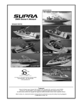
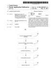
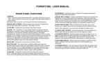
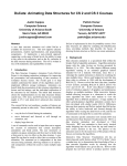
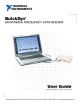
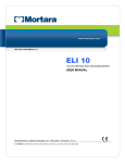
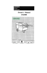
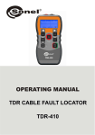
TS®100 Cable
Fault Finder
User’s Guide
No part of this publication may be reproduced, stored on a retrieval system, or transmitted, in any form or by any means
electronic, mechanical, photocopying, recording, or otherwise, without the prior written permission of Harris Corporation.
The use of trademarks or other designations is for reference purposes only.
NOTICE
Harris Corporation makes no warranties about this document. Harris Corporation reserves the right to make hardware and
software changes to the product described within this document without prior notice and without obligation to notify any
person of such revision or change.
TRADEMARKS:
TS is a registered trademark of Harris Corporation.
REGULATORY INFORMATION
WARNING: This equipment has been tested and found to comply with the limits for a Class B digital device, pursuant to part
15 of the FCC rules. These limits are designed to provide reasonable protection against harmful interference in a residential
installation. This equipment generates, uses and can radiate radio frequency energy and, if not installed and used in
accordance with the instructions, may cause harmful interference to radio communications. However, there is no guarantee
that interference will not occur in a particular installation. If this equipment does cause harmful interference to radio or
television reception, which can be determined by turning the equipment off and on, the user is encouraged to try to correct
the interference by one or more of the following measures:
•
•
•
Reorient or relocate the receiving antenna.
Increase the separation between the equipment and receiver.
Connect the equipment into an outlet on a circuit different from that to which the receiver is connected. Consult the
dealer or an experienced radio/TV technician for help.
Network Support Division | 809 Calle Plano | Camarillo, CA 93012-8519 USA
www.harris.testsets.com 1-800-437-2266
©2000 Harris Corporation
Written/Printed in USA. 0II-728063-001, Issue 4, February 2003
Declaration of Conformity
Manufacturer: Harris Corporation
Network Support Division
809 Calle Plano
Camarillo, CA 93012 U.S.A.
Ed Zoiss, Director of Engineering
Importer:
Signature:
_________________________________
_________________________________
_________________________________
_________________________________
Standards Used:
• 47 CFR Part 15 Subpart B
• ICES-003 Issue 3
• AS/NZS 3548
• EMC Directive 89/336/EEC
• EN 55022:98
• EN 61326:97 A1:98 Annex C
• EN61000-4-2
• EN61000-4-3
• LV Directive 73/23/EEC
• EN610010.1 (1993)...
EMC and Safety Compliance were evaluated by NTS, Fullerton, CA, USA
EMC Report #271-2157-1-0-NE
Product Name: TS100 Cable Fault Finder
Model Number(s): 26500-000 and 26500-500
Harris Corporation officially declares the test equipment listed above is in conformity with Electromagentic
Compatibility Directive 89/336/EEC and Low Voltage Directive 73/23/EEC based on test results performed
in a typical configuration. This Conformity is indicated by the following symbols representing the European
Community and compliance organizations:
iii
SAFETY INFORMATION
Read First Before Use
WARNING:
Means conditions and hazards may pose risk to user.
CAUTION:
Means conditions and hazards may damage the test set.
The following IEC symbols are used either on the test set or throughout the
manual:
See Manual for details
Earth Ground
Conformité Européenne
CSA/CAN C22.2 No. 1010.1-92 UL/ANSI 3101-1
iv
Contents
■
SAFETY INFORMATION
iv
■
DESCRIPTION
1
■
■
■
Design Features
1
■
Physical Characteristics
1
OPERATION
2
■
Quick Start
2
■
PowerTone™ Positive Identification System
3
■
Velocity of Propagation (VOP)
5
APPLICATIONS
5
■
Multi-Wire Environment
6
■
Conduit
6
■
Inventory Management
7
■
Speakers, Transformers, Light Bulbs,
TV Sets, Telephone, DC Loads, etc.
9
■
TIME DOMAIN REFLECTOMETRY (TDR)
TECHNOLOGY
■
MAXIMUM LENGTH
12
■
FREQUENTLY ASKED QUESTIONS
12
■
TROUBLESHOOTING TIPS
14
■
MAINTENANCE
15
■
WARRANTY
15
■
RETURN OF EQUIPMENT
16
■
SPECIFICATIONS
16
v
9
This page intentionally left blank
vi
DESCRIPTION
IMPORTANT SAFETY PRECAUTION
Legal requirements may exist regarding
permission to connect equipment to a
Telecom network operated by a public
network operator.
CAUTION:
The operator of this instrument is advised
that if the equipment is used in a manner
not specified in this manual, the protection
p ro v i d e d b y t h e e q u i p m e n t m a y b e
impaired.
T h e T S 1 0 0 C a bl e Fa u l t F i n d e r i s a
p o r t a b l e h a n d h e l d d ev i c e u s e d b y
installers, repair technicians and other
authorized personnel for locating problems
on installed cable pairs and managing
cable inventory.
Design Features
Design features of the TS100 include:
■
Bright .4 inch LED display.
■
Up to 4 readings per second.
■
Audible indication of shorted wires
and external voltage greater than 15
VAC.
■
Automatic adjustments.
■
Tone injection with the PowerTone™
positive identification system.
■
Input protected to 250 VAC.
■
Components protected against
damage from moisture.
■
Fifty hour battery life, intelligent
auto-off.
■
Low battery indicator.
■
Uses 4 AA batteries (included).
■
High strength plastic (ABS) housing.
■
Easy to use.
Physical Characteristics
■
Tests all common cable pairs.
■
Provides low cost protection against
lost time due to cable and connector
problems.
On the front of the TS100 (see Figure 1),
there is a four character LED display that
reads out the length of cable to a detected
fault. The same display flashes an LED
when the unit’s batteries are low.
■
Single button operation.
■
Up to 3000 feet, dependent on cable
type.
■
Accurate to ±2 feet for short cables.
■
Accurate to ±5 feet for cables from
10 feet to 200 feet and ±3% and ±5
feet for cables longer than 200 feet.
TS100 Cable Fault Finder
There are three buttons on the front of the
unit (see Figure 1). The larger button,
labeled ON/STANDBY, is used to turn the
unit on and off. The two smaller buttons
are used to adjust the unit’s Velocity of
Propagation (VOP) up or down. Notice the
label on the battery door. It lists the VOP
for several common cable types and
provides brief instructions on how to set
the unit’s VOP.
1
A female BNC (British Naval Connector) is
mounted on the top of the TS100 (see
Figure 1).
Input Connector
The line cord (test leads) supplied with the
unit are connected here. Be sure to only
use the line cord shipped with the unit. Any
other type of line cord may r esult in
incorrect measurements.
LED
Display
Low Battery
LED
ON / STANDBY
For information on availability of additional
line cords (test leads) and accessories,
contact your local Harr is author ized
distributor.
OPERATION
Battery Door
(on Back of Unit)
Quick Start
Up
WARNING:
Down
HAZARDOUS VOLTAGE
■
ts100_001
Figure 1. Physical Characteristics
The battery compartment (see Figure 1) is
located on the back of the unit. When
installing batteries, be sure to observe the
correct polarity. The polarity is marked on
the inside of the battery compartment.
■
CAUTION:
Refer to the operating instructions for
correct use of the BNC connector.
2
To avoid electric shock, disconnect
measuring terminals before opening
the battery door. DO NOT USE the
unit to test cables that may have
hazardous voltages present. When the
TS100 Cable Fault Finder alerts you
to the presence of high AC voltages,
CAREFULLY DISCONNECT IMMEDIATELY to prevent any personal
harm. Hazardous DC voltages can be
present on any cable at any time. The
TS100 does NOT detect or indicate the
presence of DC voltages. Use care
when connecting to cables.
Always handle the clip leads and the
cables by their insulation, NEVER
directly by the conductive part of the
clip or wire. Use only the insulated
clips provided to connect to any wire
or cable.
TS100 Cable Fault Finder
The TS100 Cable Fault Finder requires 4
AA batteries (included) to be installed in
the battery compartment located on the
back of the unit.
WARNING:
To avoid electric shock, ensure that the
unit is not connected to anything before
removing the battery door.
To remove the batter y door, push the
plastic tab in the direction of the arrow and
lift off the door. Observe correct polarity
when inserting the batteries. Reinstall the
battery door prior to connecting the unit to
anything.
Attach the line cord to the BNC connector
at the top of the unit. Turn the unit on by
pressing the ON/STANDBY button. The
TS100 performs a self test each time it is
powered on. During the self test, the unit
will briefly display 8.8.8.8. and then it will
default to 0 feet.
CAUTION:
When testing telephone cables, the TS100
should only be used to test non-working
circuits. If accidentally connected to a
working ADSL or hi-cap circuit, the
TS100 will cause an outage.
To perform a test, attach line cord clips to a
pair of wires at one end of the cable you
are testing. The TS100 will display the
TS100 Cable Fault Finder
distance (in feet) to the closest fault it finds.
It will display Err if the unit doesn’t find a
fault within its measurement range.
To s ave b a tt e r y power, t he u n i t w i l l
automatically shut down after five minutes
if it is not connected to anything, or one
hour after you connect to a cable. Also, if
the ON button is held down for more than
20 seconds, the unit will shut down. This is
to prevent batter y drain should some
object in your tool box be leaning on the
button.
PowerTone™ Positive Identification
System
Whenever the TS100 is ON, the unit
injects a tone onto the pair of conductors
the unit is connected to (see Figure 2).
This tone is compatible with most tone
receivers. The tone is transmitted
concurrently with fault locating measurements.
The TS100 Cable Fault Finder has a
u n i q u e c a p a b i l i t y bu i l t i n t o i t s t o n e
g e n e r a t o r. T h e i n j e c t e d t o n e h a s 5
frequency and cadence options. This
allow s the user to ensure positive
identification of the wire pair at the far end
of a cable by following this procedure:
1. At one end of the cable run, connect
the TS100 to the pair of wires you want
to trace.
2. Turn on the TS100. The unit will
automatically transmit the cable locator
tone.
3
Tone is injected
into cable
Tone Receiver
Tone changes when cable
is momentarily shorted
TS100 injects a tone
into the pair of wires.
This tone changes to
one of five different
tones when the wire pair is
momentarily shorted.
Use this feature to
POSITIVELY IDENTIFY
the wire pair at the far end.
ts100_002
Figure 2. Tone Injection Positive Identification System
3. At the other end of the cable run, use
your tone probe to find the pair of wires
by probing for the pair that produces
the loudest tone in your probe.
4. Short the pair of wires together then
release the short.
a. If you DO NOT hear a change in the
cadence of the tone, then you have
not located the pair of wires the
TS100 is connected to.
b. If you DO hear a change in
cadence, then you have POSITIVE
CONFIRMATION that you have
found the pair of wires the TS100 is
connected to.
dense and high noise cable environments.
The cable locating tone is not audible on
the TS100’s buzzer. To hear the cable
locating tone, place a tone probe near the
pair of wires the TS100 is connected to.
The TS100’s buzzer provides audible
beeping to indicate various conditions the
unit may encounter during operation.
Table 1 provides a summary of the unit’s
buzzer and visual display indications under
various conditions.
Table 1. LED Readout and Buzzer
Indications
Condition
In s i tua ti on s wh er e you a r e us in g a
companion tone receiver to identify a
particular wire pair, the tone received from
n e i g h b o r i n g w i r e s m ay b e i n d i s t i n guishable from the tone heard on the
target pair of wires. The Power Tone
Positive Identification System allows you to
positively identify the target pair of wires in
4
Readout
Buzzer
Normal
Conditions,
Open Cable
LLLL
Off
Normal
Conditions,
Shorted Cable
LLLL
Continuous
On
The Cable is too
Long to Measure
–Err
Staggered
TS100 Cable Fault Finder
Table 1. LED Readout and Buzzer
Indications (Cont’d)
Condition
Readout
Buzzer
A DC Load (light
bulb, TV, etc.) is
Detected
–Err
Staggered
■
Different cables have different VOP
settings.
■
The correct VOP insures the most
accuracy in fault locating and in
inventory management.
Where LLLL = the length to the fault.
To enter the VOP adjustment mode, turn
the unit on while holding down either the
UP or DOWN button. In this mode, the
display alternately shows the VOP setting VV- and the calculated length LLLL.
Pressing either the UP or DOWN button
will cause the currently displayed item to
remain displayed for several seconds,
allowing the adjustment of the VOP setting
or the resultant length. If you know the
VOP, use the UP and DOWN buttons to
adjust the setting of -VV- to that value.
Velocity of Propagation (VOP)
Note: While the TS100 is in VOP adjustment mode,
tone is not injected into the cable.
The only cable characteristic that the
T S 1 00 C a bl e Fa u l t F i n d er d oe s n o t
automatic ally compen sate fo r is the
Velocity of Propagation (VOP). In most
uses, the default VOP setting of -66- is
appropriate.
H o w ev e r,
some
circumstances will require an adjustment
of the VOP setting. The most common
circumstance is the measurement of the
amount of cable in a box or on a spool.
If you have a known sample length of the
cable, 200 feet or longer (such as an
unopened box of wire) use the UP and
DOWN buttons to adjust the displayed
length LLLL to the known length of the
sample. This setting will be remembered
by the TS100 Cable Fault Finder until you
change out the batteries or change the
VOP again.
VOP is:
To exit the VOP adjustment mode, simply
turn the unit OFF.
>15 VAC is
Detected
8888
Flashing
Rapid
Low Battery,
Open Cable
L.LLL
Off
Failed Self Test
8888
Off
This Cable
Cannot be
Measured
–Err
Staggered
■
A specification of the cable
indicating the speed at which a
signal travels down the cable. A
VOP of 66 means the signal travels
at 66% of the speed of light.
TS100 Cable Fault Finder
APPLICATIONS
The TS100 locates opens, short circuits,
and crosses in any two metallic conductors
(i.e., twisted, untwisted, coax, copper,
aluminum, and steel (see Figure 3).
5
Open
Length of Cable
600 feet
600 ft.
Length of MultiConductor Cable
on Spool
700 feet
700 ft.
on Spool
Short
Short in Middle
of Cable
40 feet
Buzz
40 ft.
Open
Open Near Start
of Cable
2 feet
2 ft.
Termination
Termination at
End of Cable
Err
Buzz
600 ft.
100
ft.
Branch in Cable
Unit Could Read
Either Branch
ts100_003
100 ft.
50
ft.
150 feet
or
200 feet
Figure 3. Testing for Length, Shorts,
Opens and Terminations
It identifies conductors using the
PowerTone feature and an inductive probe
(not included) (see Figure 2). Tone can be
s e n t b e twe en t wo t ec h n i c i a ns t o ID
multiple pairs. Because the unit buzzes
when it detects a shor t circuit, it also
serves as a circuit (i.e., continuity) tester.
Multi-Wire Environment
When testing wires in a multi-wire
environment such as 4 wire telephone
cable, 8 wire CAT-5 cable, 12-2 with
6
ground AC wire, or several THHN wires
inside a conduit, a shor t could exist
between any number of the conductors
including a shield or the conduit. In order to
detect the short, you must connect the unit
to the wires that are shorted. This means
that to fully test a multi-wire environment,
you must check every wire against every
other wire including the shields and
conduits. If, due to other indications, you
a l r e a d y k n ow w h i c h w i r e s h ave t h e
problem and are using the TS100 Cable
Fault Finder to find the distance to that
problem, then you only need to test those
wires.
While a speedy way to test many
conductors against a conduit or shield is to
connect all the conductors to one clip lead
and the shield to the other lead, this will
reduce the impedance of the cable and
may fall below the operational limits of the
unit. It is more reliable to test the wires
individually.
Conduit
Note: When the wires exit the conduit and become
physically separated, they will no longer be seen by
the TS100 and thus the length displayed will
represent only the length of wire within the conduit.
The TS100 reacts to metal conduit as
though it was just another wire in the multiwire environment. As such, if the conduit is
broken or disconnected part way in the
run, the wire-to-wire readings may be
correct, but wire-to-conduit readings will
only read as far as the continuous conduit.
TS100 Cable Fault Finder
Also, if wire is looped out of the conduit,
such as at an elbow or junction box, as
long as the length of this uncontained wire
is less than 12 inches, the wire to conduit
r e a d i n g s w i l l b e u n a f fe c t e d b y t h e
uncontained wire. If more than 12 inches
is uncontained, the unit will see this as an
open in that wire.
Inventory Management
The TS100 is an inventory management
tool. It measures lengths of wire or cable
while still on the reels.
The ability to measure the length of multiconductor cable remaining on its spool is
valuable for both job-site and warehouse
personnel. Remember that with the
TS100, you can measure the length from
JUST O NE END of a PAIR of wires,
allowing you to take inventory without
unspooling the cables or even having to
move the spools at all.
At the job-site, you can determine if the
cable remaining on your spool or in your
box will be sufficient for the job at hand.
This will save you an unnecessary trip to
the warehouse for more cable, and help
you avoid running out of cable in the
middle of an installation.
There are two points to remember when
measuring the length of wire on a spool:
■
The wire length must be within the
range of the TS100 (see Table 2).
TS100 Cable Fault Finder
■
The accuracy of the measurement
will be optimum if the VOP is set
correctly for the type of wire being
measured. See Table 2 and Table 3
for a list of VOPs for common cable
types.
In the warehouse, you can QUICKLY
measure the cable remaining on all your
spools, allowing you to select the right
spool for each job. Additionally, by keeping
a record of the prior inventory, you can
determine how much wire was used on the
current job.
Table 2. Table of VOP Values and
Maximum Length for Specifically
Identified Cables
VOP
Maximum
Length
(Feet)
64
2000
Lucent 1024 006ABE 6/
24 W1000, 6 pair CAT3
(Blue-White)
63
1500
BICC General Aerial
Service Wire (ASW)
2/22, 2 Pair
Drop Wire
61
2000
Superior Essex, 4 pair
CAT3 Plenum (not pair
dependent)
60
1500
BICC General, 24 AWG
CMX Outdoor CMR
Station Wire
58
1000
BICC General crossconnect 24 AWG twisted
pair on ORIGINAL
SPOOL
Specifically Identified
Cable
7
Table 2. Table of VOP Values and
Maximum Length for Specifically
Identified Cables (Cont’d)
VOP
Maximum
Length
(Feet)
66
2500
Berk-Tek, CAT5
(Orange-White)
68
2500
Superior-Essex Cobra
CAT5 CMR (OrangeWhite)
72
2500
Superior-Essex Cobra
CAT5 CMP (OrangeWhite)
82
1000
CommScope 5726, RG6
CATV Coax
81
1000
CommScope 2275V,
RG6 CATV Coax
79
1000
CommScope 5571,
RG59, TV Coax
67
500
Belden 88760 2 wire
shielded 18 AWG, RedBlack
68
2000
Triangle Wire and Cable,
type NM-B 12/2W/G,
Black-White
Table 3. Table of VOP Values for
Other Cables
VOP
Cable Type
CommScope Drop
87
CommScope Trunk
63
RG58/U 50 Ohm Network Coax
80
RG59 TV Coax
64
Service Wire
83
Times Fiber Drop
90
Times Fiber Dynafoam
87
Times Fiber Trunk
93
Trilogy Trunk
Channel Master Polyclad
Model 9354 300 Ohm
Foam Antenna Wire
68
Twisted Pair, Gel Filled 19 AWG
64
Twisted Pair, Gel Filled 22 AWG
Triangle Wire and Cable,
type NM-B 12/2 W/G,
Black-Ground
62
Twisted Pair, Gel Filled 24 AWG
60
Twisted Pair, Gel Filled 26 AWG
68
Twisted Pair, Paper 22 AWG
Belden 88760 2 wire
shielded 18 AWG, Red/
Black-Shield
57
500
BICC General, E22025,
Red-Black
2000
67
Specifically Identified
Cable
82
Carol C1156 RG-174/U
71
Maximum
Length
(Feet)
Belden Drop Foam
500
1000
VOP
78
64
73
8
500
Specifically Identified
Cable
Table 2. Table of VOP Values and
Maximum Length for Specifically
Identified Cables (Cont’d)
TS100 Cable Fault Finder
Table 3. Table of VOP Values for
Other Cables (Cont’d)
VOP
Cable Type
66
Twisted Pair, Paper 24 AWG
65
Twisted Pair, Paper 26 AWG
72
Twisted Pair, PIC 19 AWG
67
Twisted Pair, PIC 22 AWG
66
Twisted Pair, PIC 24 AWG
64
Twisted Pair, PIC 26 AWG
Remember, the TS100 works on TWO
conductors. Single conductor spools can
not be measured with the TS100 Cable
Fault Finder.
Speakers, Transformers, Light Bulbs,
TV Sets, Telephone, DC Loads, etc.
The TS100 Cable Fault Finder is a cable
tester. Sometimes, there are devices
connected to the cable you are testing that
can prevent the TS100 from making a valid
reading. The software makes the best
decisions it can when faced with unusual
conditions, but may not always be able to
ignore connected devices. If you get a
highly unstable or clearly non-valid reading,
please check for devices connected to the
cable.
TS100 Cable Fault Finder
TIME DOMAIN REFLECTOMETRY
(TDR) TECHNOLOGY
Note: This section delves deeper into the Theory of
Operation. You can skip this section and still use the
unit effectively by reading the other parts of this
manual. However, it is worth going through this
material if you want more insight into how the unit
works.
One of the keys to understanding how the
TS100 works is to first understand that a
pair of wires has a fixed impedance as long
as the wires of the pair are kept in the same
geometrical relationship to each other. A
pair of wires (either standalone or within a
multi wire cable) is designed to have a
constant wire-to-wire impedance. If the
physical relationship of the wires in the pair
is altered during the wire run, then there
will be a change in impedance at the point
where the physical relationship changes.
For example, if one or both wires of the pair
are broken (open), or they are shorted to
each other, or they become sufficiently
s e p a r a t e d f r o m e a c h o t h e r, t h e i r
impedance will change. The TS100 looks
for these changes in impedance. If the
impedance change is large enough, (e.g.,
such as that caused by a break in one of
the wires of the pair), the TS100 will detect
the impedance change and will display the
length of the wire up to the impedance
change. From the previous information, it
should be easy to deduce that the TS100
can measure the length of a pair of unterminated wires, because, the open circuit
at the far end causes a ver y large
impedance change.
9
The TS100 Cable Fault finder uses Time
Domain Reflectometry (TDR) to determine
the length of the target cable. A TDR,
much like RADAR, sends a pulse down the
pair of wires. Part of that pulse reflects off
any impedance variations in the pair of
wires. All of the reflections, together with
the original pulse, combine to make an
electrical signal (TDR waveform) that has
var ious flat and bumpy sections that
represent the star t, the impedance
changes, and the end of the cable. The
size and shape of the flat and bumpy
sections depend on the distance to the
impedance changes and the magnitude of
the impedance changes.
For example, two runs of 12/2 AC wire
joined with a splice will have a TDR
waveform with 2 flat sections separated by
a bump. The two flat sections represent
the lengths of the two sections of wire. The
small bump in the middle represents the
small impedance change at the splice
point. The large bump at the end
represents the large impedance change at
the end of the wire run (see Figure 4).
Harris’ TDR technology examines this TDR
waveform (see Figure 4), looking at the
sizes of the flat sections and the bumps.
T h e s o f t wa r e d e c i d e s w h i c h o f t h e
e l e m e n t s o f t h e w a v e fo r m i s m o s t
representative of the common problems
encountered in the wiring industries and
reports the distance to that element.
Wire Connectors
12/2 AC Wire
TDR Waveform
ts1_006
Reflection from Wire Connectors
Reflection from End of Cable
Figure 4. TDR Waveform
In the case of the waveform in Figure 4,
the TS100 will report the distance to the
end of the wire run and will ignore the
small bump in the middle because it is too
small to be considered a problem.
10
If more than one problem exists on the
cable, the software in the TS100 Cable
Fault Finder only repor ts the nearest
problem.
TS100 Cable Fault Finder
The actual result of the measurement is
the TIME to the fault. The software in the
unit conver ts the measured time to a
length by multiplying the time by the speed
of the electrical signal in that particular
cable. That speed is represented as a
percentage of the speed of light and is
called the Velocity of Propagation (VOP).
The actual formula we use is:
Length= Time in billionths of a second X VOP
0.9835
2
The time is divided by two because the
signal traveled the length of the cable
twice. Once when it left the unit and went
to the failure point, and again when it
reflected back to the unit to be detected.
The speed of light expressed in billionths
of a second per foot is 0.9835 (about a
billion feet per second).
This characteristic speed of the signal for a
particular cable is not normally a tightly
controlled part of the cable manufacturing
process and can vary widely from one
manufacturer to another as well as from
one box of cable to the next. As with all
TDR based cable measurement tools, the
TS100 measures TIME within specified
tolerances, but the displayed LENGTH is
the result of the calculation with the user
selected VOP and is only as accurate as
that selected VOP. For most uses, a length
reading with an incorrectly set VOP is
sufficiently accurate to locate the fault in
the cable. After all, an installed cable is
TS100 Cable Fault Finder
hardly ever run in a straight line. It can be
stapled along the 2x4, laid diagonally in
the ceiling, and coiled behind the junction
box, all of which is not visible. Also,
c o m m o n s e n s e s h o u l d p r eva i l . Fo r
example, if the unit reports an open at 80
feet, and you can see a junction box at
about 70 feet, your first step should be to
check at the junction box.
H o w ev e r, fo r s o m e u s e s s u c h a s
measuring the remaining cable in a box, it
is important to set the VOP correctly in
order to achieve the accuracy desired.
Depending on the cable constr uction
(shielded, twisted, etc.), insulating material
(foam, air, fiber, etc.), and conductors
tested (wire-to-wire, wire-to-shield), coiling
the cable on a spool or in a box may alter
its VOP.
Additionally, other conductors in close
proximity to the conductors being tested
can affect the VOP. For example, a solitary
12 gauge THHN in a 1 inch conduit has a
VOP of 82, while that same wire in a ½
inch conduit filled with other wires has a
VOP of 72.
Note: The actual VOP of any particular cable is
dependent on the conductor spacing and the
material between the conductors and could vary by
as much as ±5 feet from the value listed in Table 2.
To help with your measurements, we have
included Table 2 and Table 3 showing the
VOP values for many cable types and
conditions.
11
MAXIMUM LENGTH
The maximum length of cable that can
correctly be measured by the TS100 is
determined by several factors. The most
significant is the signal loss of the cable
itself. When the signal loss in a particular
cable is large enough, the unit cannot
“hear” the TDR echo and cannot
determine the length of that cable. In this
situation, the unit displays “Err” on the
readout. The amount of signal loss in a
cable is determined by the characteristics
of that cable and its length. The maximum
length shown in Table 2 is the length above
which the unit is not expected to be able to
make a valid measurement. For lengths
above those stated in Table 2, the unit
accuracy is not specified.
FREQUENTLY ASKED
QUESTIONS
Q: How do I calibrate or perform a self test
of the functionality of the unit?
A: There are no adjustments inside the
unit, and the internal coating protects the
critical components from moisture and
contaminants. There is nothing to
calibrate. A self test is performed by the
unit every time you turn it on. Since there
is no loss of any settings when the unit is
off, there is no penalty to just turning it off
and on if you wish to perform a self test.
The unit displays 8.8.8.8. during the self
test.
Q: Does it matter which clip lead I connect
to which wire in the cable under test?
A: Not for any of the testing functions.
However, when you connect the unit to a
12
cable, if you connect the red lead first, an
invalid reading may be displayed until the
full connection is made with both leads.
The unit’s Time Domain Reflectometry
(TDR) technology requires both leads to
be connected to the wire pair or cable in
order to determine its length. While using
only one of the leads is useful in tracing
cable position with the injected tone, both
leads are required to make valid length
measurements.
Q : W h a t d o e s t h e L O W B AT T E RY
indicator really indicate?
A: The LED comes on (flashes) when the
batter y voltage falls below 4.1 volts,
indicating that you should replace the
batteries. While the unit will continue to
operate for at least 1 hour below this
voltage, some readings may be less
accurate.
Q: I tested an orange outdoor 25 foot
extension cord and the display read 19
feet. Is the unit broken?
A: No. The accuracy of the reading is
dependent on the setting of the VOP.
While the nominal setting for general
testing is -66-, the VOP for that kind of
cable is -56-. To improve the accuracy of
length measurements for that or any cable,
c h a n g e t h e VO P a s s h o w n i n t h e
instructions in the Velocity of Propagation
section.
Q : W hy d o e s t h e l e n g t h r e a d i n g
sometimes change a small amount when I
open and short the far end of a test cable?
TS100 Cable Fault Finder
A: There are two causes. The first is that
this is a characteristic of the measurement
technique used in almost all low and
medium cost cable length test tools. In the
case of the TS100 Cable Fault Finder, the
variance occurs in only a few cable types
and both readings are within the specified
accuracy of the instrument. The second
cause occurs when the cable is coiled, as
in a box or on a spool. The magnetic field
caused by the TDR signal itself couples
across to other par ts of the cable and
changes the character istics of the
reflections.
Q: Why, on some cables, does the number
displayed on the readout jump between 2
or 3 different values?
A: As the TDR signal travels down a cable,
it loses some of its strength. At some
point, the noise on the cable has an
amplitude similar to the reduced strength
TDR signal and will influence the
measurement results. The unit’s software
filters out many of the noise related
variations in the displayed length, but
some variations do get through.
Q: I accidentally cracked the plastic
housing, does this affect the moisture
protection of the components?
A: Not at all. The component protection is
provided by a coating on the components
and Printed Circuit Board (PCB).
should not use the unit until the plastic is
repaired or replaced.
Q: Can this unit measure the length of
single conductor wires like THHN?
A: No. All TS100 measurements must be
made on TWO conductors from the SAME
END of a cable.
Q: If I touch the bare metal of the wires or
c li p l eads, wil l t he m eas ure ment be
affected?
A: A fter B OTH c li ps ar e con nec ted,
measurement results will ordinarily not be
affected if inappropriate human contact is
made with the input connectors. Under
moist conditions, if a large surface area of
cable is in contact with moist skin, some
readings may be affected.
Q: On multi-conductor cables with a short
between 2 of the conductors, I sometimes
read an ‘open’ at twice the known length of
the cable.
A: If the cable has more than 2
conductors, and a short exists at the far
end between one of the conductors you
are connected to and a conductor you are
not connected to, the displayed length will
be the SUM of the lengths of the
conductors joined by the short. TS100 can
only correctly test the 2 conductors you are
connected to. See the Applications section
for multi-conductor cables.
However, if sufficient plastic is missing
then a possible shock hazard exists. You
TS100 Cable Fault Finder
13
Q: When testing a set of wires that go into
a conduit, I sometimes get a reading of 0
or 1. Why?
A: If there is more than a foot or so of wires
that are physically separated before they
enter the close confinement of the conduit,
this will look to the unit like an open at the
start of the cable. Remember that TS100
reports the FIRST failure that it finds. Try
bringing the two wires of the pair closer
together for the path from TS100 to the
entry to the conduit.
Q: When connecting to a 6 foot piece of 50
ohm Coax with the alligator clips, the unit
reads 8 feet. What’s up?
A: When measuring a low impedance
small cable (less than 15 feet), the clip
leads can add up to 2 feet of length. For
longer or high impedance cables, the clip
leads have no effect.
Q: How does the unit react to a speaker or
a transformer at the end of a cable?
A: A speaker or a transformer is actually a
large coil of wire. This will usually cause
the length reading to be larger than that of
the cabl e alone. A moderate power
speaker will add 500 feet to the length
reading. Some combinations of speakers
and transformers connected to the cable
may prevent the unit from making a valid
reading.
14
TROUBLESHOOTING TIPS
1. The display remains at 8.8.8.8. after
power on.
The self test has failed. The batteries
may be weak or the unit has water
inside. Try changing the batteries or
drying the unit.
2. The unit reads less than 10 feet
regardless of the length of the cable.
The connection to the cable is broken.
Check your connection to the cable for
dirt or insulation. Also, test the clip
leads by shorting them and listening for
the buzzer. You can also visually check
the center connection of the BNC for
damage.
3. The unit does not respond to any
button presses.
The batteries could be dead or inserted
incorrectly, or the contacts are dirty or
broken. Please ensure that nothing is
connected to the input connector before
opening the battery door, and then
check the battery installation. Remove
the batteries and check the contacts for
dirt or damage. Please observe correct
polarity when inserting the batteries.
TS100 Cable Fault Finder
MAINTENANCE
WARNING:
■
■
These servicing instructions are for use
by qualified personnel only. To avoid
electric shock, do not perform any
servicing other than that contained in
the operating instructions unless you
are qualified to do so.
Disconnect clips from any metallic
connections before performing any
maintenance.
CAUTION:
Do not use CRC Cable Clean ® or any
similar chlorinated solvent on the TS100.
Doing so will damage the TS100 Cable
Fault Finder.
There are no user serviceable components
or adjustments in the TS100. Do not open
the housing as handling of the PC board
could remove the moisture protection
coating or apply a static charge that will
damage sensitive components.
Note: Opening the housing will void the Warranty.
Moisture will not harm the unit. However,
moisture can provide a leakage path that
may conduct hazardous voltages to you.
DO NOT USE the unit if wet.
If moisture should get inside the unit, let
the unit dry at normal room temperature for
24 hours. DO NOT HEAT THE UNIT.
Daily use of your TS100 Cable Fault Finder
results in various liquids, dirt, and other
foreign material building up on your unit.
The TS100 Cable Fault Finder may be
cleaned by using a soft cloth with soap and
water. Do not use a petroleum-based or
chlorinated cleaning agent as it will harm
the unit.
WARRANTY
Harr is Cor poration warrants that the
TS100 Cable Fault Finder shall be free of
any defects in parts or workmanship, for a
period of eighteen (18) months from the
date of manufacture, if used under Harris
operating specifications.
THIS IS THE ONLY WARRANTY MADE
BY HARRIS CORPORATION AND IS
MADE EXPRESSLY IN LIEU OF ALL
OTHER WARRANTIES EXPRESS OR
I M P L I E D, I N C L U D I N G B U T N OT
LIMITED
TO
ANY
IMPLIED
WARRANTIES OF MERCHANTABILITY
OR FITNESS FOR ANY PARTICULAR
PURPOSE.
Should any parts or workmanship prove
defective, Harris Corporation will repair
with “not used” or reconditioned parts, or
replace the Product, at Harris’ option, at no
cost to the Buyer except for shipping costs
fr om t he B u ye r ’s l o c at i o n t o H a r r i s ’
location. This is the Buyer’s SOLE AND
E X C L U S I V E R E M E DY u n d e r t h e
Agreement.
All incidental or consequential damages
shall be excluded.
TS100 Cable Fault Finder
15
THIS WARRANTY DOES NOT EXTEND
TO PRODUCTS WHICH HAVE BEEN
SUBJECTED TO NEGLECT, ACCIDENT
OR IMPROPER USE, NOR TO UNITS
W H I C H H AV E B E E N A LT E R E D O R
R E PA I R E D B Y OT H E R T H A N
AUTHORIZED HARRIS PERSONNEL.
Table 4. Specifications (Cont’d)
Parameter
Working Limits
Input Protection
250V RMS AC, Continuous
or Intermittent.
Moisture
To return the test set to Harris, first obtain
a Return Authorization (RA) Number from
our Customer Ser vice. This retur n
authorization number must be clearly
mar ked on the shipping label, or the
container will not be accepted by Harris.
See the following sample label:
If the unit is exposed to
water, some may get inside,
but it will suffer NO
DAMAGE. See the moisture
notes in the Maintenance
section.
Impedance
Range
To:
HARRIS CORPORATION
809 Calle Plano
Camarillo, California, USA 93012-8516
Attention: Customer Service RA #XXXXXX
35 to 330 Ohms with autocompensation within this
range. Cables with an
impedance outside this
range will not be properly
tested and may produce
erratic or incorrect readings.
Maximum
Length
2500 feet on certain cable
types, 2000 feet on most
cable types, and 500 feet on
very lossy cables. The unit
will display –Err if the cable
is too long to be correctly
measured.
Representative
Maximum Cable
Lengths
2500 feet — CAT-5 Twisted
Pair
2000 feet — 12/2 AC Wire
1000 feet — RG-6/U TV
Coax
500 feet — RG-174/U Coax
Minimum Length
No minimum length.
Minimum non-zero reading is
two feet.
Length Accuracy
±2 feet for cables less than
10 feet.
±5 feet for cables longer than
10 feet and shorter than 200
feet.
±3 % and ±5 feet for cables
longer than 200 feet.
RETURN OF EQUIPMENT
SPECIFICATIONS
Table 4 lists the specifications for the
TS100 Cable Fault Finder.
Table 4. Specifications
Parameter
Power
Reverse Battery
Protection
16
Working Limits
4 AA alkaline batteries,
providing 50 hours of “on”
time. To extend battery life,
remove batteries when not in
use. Disconnect measuring
terminals before opening the
battery door.
No damage to the unit will
occur if the batteries are
installed backwards.
TS100 Cable Fault Finder
Table 4. Specifications (Cont’d)
Parameter
Working Limits
High Voltage
Detection
An AC voltage of more than 5
to 15 Volts RMS will trigger
the High Voltage Warning.
Measurement
Rate
Maximum of 4 complete
measurements per second,
decreasing to 2 seconds per
measurement based on
cable size and uniformity.
VOP
Measurement
Technology
Tone Injection
Adjustable from -20- to -99-,
retained during power off.
Default to -66- when
batteries are changed.
Time Domain Reflectometry
(TDR) with 50 Ohm drive
impedance, 6 volt maximum
pulse height. (Patents
Pending).
Table 4. Specifications (Cont’d)
Parameter
Working Limits
Cable Type
Virtually all two or more
conductor cables.
Low Battery
Indicator flashes when
battery voltage falls below
4.1 volts.
Temperature
0 to 55 degrees C operating;
0 to 70 degrees C storage.
Humidity
0 to 80 percent operating; 0
to 100 percent storage.
Weight
1 pound, with batteries and
clip leads.
Operating
Altitude
10,000 feet max
This product has been safety certified for indoor
use only.
Approximately 1 kHz at an
amplitude of 80 percent of
battery voltage. Variable
frequency and cadence.
Tone characteristic is
changed as cable condition
changes to “normal-open”
from any other condition.
TS100 Cable Fault Finder
17
Network Support Division | 809 Calle Plano | Camarillo, CA 93012-8519 USA
www.harris.testsets.com 1-800-437-2266
©2000 Harris Corporation
Written/Printed in USA. 0II-728063-001, Issue 4, February 2003