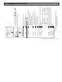
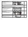
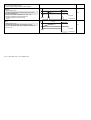
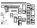
1
INSTALLATION AND PROGRAMMING MANUAL 2nd Edition Manufacturer: NIVELCO Process Control Co. H-1043 Budapest, Dugonics u. 11. Phone: (36-1) 889-0100 Fax: (36-1) 889-0200 e-mail: [email protected] www.nivelco.com BKI 04 ATEX 106X prw1101a0600p_02.doc 1 / 58 TABLE OF CONTENT 1. 2. 3. 3.1. 3.2. 4. 4.1. 4.2. 4.2.1. 4.2.2. 4.2.3. 5. 5.1. 5.1.1. 5.1.2. 5.1.3. 5.1.4. 5.1.5. 5.2. 5.2.1. 5.2.2. 5.2.3. 5.3. 5.4. 5.5. 5.6. 5.6.1. 5.7. 5.8. 5.9. 5.10. APPLICATION .............................................................................4 TECHNICAL DATA .....................................................................4 ORDER CODE .............................................................................6 DIMENSIONS ...................................................................................7 SAFETY REGULATION OF EX APPROVED UNITS ...................................8 ELECTRIC CONNECTION ..........................................................9 ARRANGEMENT OF THE CABLE TERMINALS ........................................9 WIRING OF THE TRANSMITTERS.......................................................10 Wiring of the 2-wire transmitters.................................................10 Wiring 4-wire transmitters ..........................................................11 Wiring of combined system ........................................................12 PROGRAMMING OF MULTICONT ...........................................13 STEPS OF PROGRAMMING ..............................................................14 Stepping between menu tables and scrolling menu points ........15 Activation of devices, relays and current generators .................16 Assignment of (relay and current) output to device....................17 Editing parameter values............................................................18 Editing characters (e.g. Short tag)..............................................19 COMMISSIONING OF NETWORK WITH MULTICONT ...........................20 Preparing transmitters ................................................................20 Wiring .........................................................................................21 Commissioning of MultiCONT ....................................................21 MAIN MENU ...................................................................................27 MULTICONT CONFIGURATION .......................................................28 PROGRAMMING DEVICES ................................................................34 REMOTE PROGRAMMING ................................................................35 Editing the linearisation table .....................................................37 RELAY CONFIGURATION .................................................................38 CURRENT GENERATOR CONFIGURATION ..........................................44 SWITCHING ON ..............................................................................45 MEASUREMENT MODE ....................................................................47 2 / 58 BKI 04 ATEX 106X prw1101a0600p_02.doc 6. 7. 8. ERRORS, ERROR MESSAGES, ERROR CODES.................. 48 PROTECTION OF SETTINGS BY HARDWARE ..................... 50 FUSE REPLACEMENT............................................................. 51 Appendix 1. 2. 3. 4. 5. MANUFACTURER’S IDENTIFICATION CODES (ID).............. 52 MULTICONT PRW-100 MENU SYSTEM ................................. 53 PROGRAMMING RELAYS....................................................... 54 PROGRAMMING CURRENT GENERATORS ......................... 55 MEASUREMENT MODE........................................................... 56 Thank you for choosing a NIVELCO instrument. We are sure that you will be satisfied throughout its use. 1. APPLICATION MultiCONT P-100 series is first of all a controller and display capable to provide powering for 2-wire devices (transmitters) and accomplish complex control tasks. Further it is a „MASTER” for all NIVELCO made smart transmitters as well as a universal interface between field devices with HART and other components of the process control system such as PC, PLC, displays and different actuators. MultiCONT P-100 units support communication with a maximum of 15 ordinary or 2 Ex certified HART-capable NIVELCO made 2- or 4-wire transmitters. Should a system contain more transmitters than one MultiCONT can handle further MultiCONT units can be organized in row by RS485. Remote programming of the transmitters and downloading of the measured data is a routine for the MultiCONT. Measured values and new values calculated from the measured ones can control different outputs such as 4 … 20 mA, relays and digital output. Large DOT matrix LCD panel facilitate a wide variety of display functions including tank content visualization. The output facilities of the basic unit can be extended with external (relay and/or current generator) modules. Explosion proof certified versions of the MultiCONT should be accommodated in non-hazardous area. 2. TECHNICAL DATA TYPE P - 1- Installation Ambient temperature PRC, PRD, PRW PRH Transmitter power supply Display Output Analogue Relay RS 485 interface HART Wall mounting -20 °C … +50 °C -30 °C … +50 °C 30 V DC 60 mA,( for Ex version: 25 VDC / 22 mA) 120 x 32 Dot-matrix/ 128 x 64 Max. 2 x 4 … 20 mA, galvanically isolated max load 500 ohm, over-voltage protection Max. 4 x SPDT 250 V AC ; AC 1. 5 A Galvanically isolated MODBUS protocol HART output signal level 0.5 ±0.1 Vpp trapezoid 1200 / 2200 Hz Minimal input signal level: 50 mVpp Input sensor resistance 255 ohm. BKI 04 ATEX 106X prw1101a0600p_02.doc 3 / 58 TYPE P - 1- Powering, relays, analogue 4 … 20 mA Cables RS 485 interface Shielded, twisted cable pair, cross section: 0.5 … 2.5 mm2 HART cabling Number of transmitters to be powered Power supply / consumption / maximum voltage Below 1500 m Shielded, twisted cable pair, min. cross section 0,5mm Over 1500 m Two shielded, twisted cable, min. cross section 0,8mm Resistance max. 75 ohm, capacitance max. 225 nF 15 ordinary or maximum 4 Ex transmitters 85 … 255 V AC 50 … 60 Hz / 12 VA / 255 Veff 11,4 … 28 V AC 50 … 60 Hz / 12 VA / 28 Veff 11,4 … 40 V DC / 11 W / 40 V DC 85 … 255 V AC 50 … 60 Hz T400 mA 11,4 … 28 V AC 50 … 60 Hz and 10,5 … 40 V DC T1A Fuses Housing material Installation Polycarbonate (PC) Wall mounting Ambient temperature PC, PD, PW PH Ingress protection - 20 °C … + 50 °C - 30 °C … + 50 °C IP65 Ex marking II (1) G [EEx ia] IIB U0 = 30 V I0 = 140 mA P0= 1 W L0 = 4 mH C0 = 200 nF Intrinsical safety data Electric protection Mass Class I/III 0.9 kg 2.1. ACCESSORIES Guarantee certificate Installation and Programming Manual Manufacturer’s Declaration 2 nos cable gland sealing 4 / 58 0.5 … 2.5 mm2 core cross section BKI 04 ATEX 106X prw1101a0600p_02.doc 3. ORDER CODE MultiCONT EXTENSION CODE Standard * Not extendable R E ENCLOSURE IP 65 IP 65 with transparent cover IP 65 with lockable transparent cover IP 65 with transparent cover and heating CODE W C D H** P INPUT 1 tx with HART 2 tx with HART 4 tx with HART 8 tx with HART 15 tx with HART – 1 CODE 1 2 4 8 M – OUTPUT CODE POWER SUPPLY CODE Display only 1 relay 2 relays 3 relays 4 relays 0 1 2 3 4 85 … 255 V AC 24 V AC / DC 85 … 255 V AC Ex 24 V AC / DC Ex 1 2 5 6 1 relay + 1x4…20 mA Analogue output 5 prw1101a0600p_02.doc 5 / 58 2 relays + 1x4…20 mA Analogue output 3 relays+ 1x4…20 mA Analogue output 4 relays + 1x4…20 mA Analogue output 4 relays + 2x4…20 mA Analogue output RS 485 interface RS 485 + 1x4…20 mA 6 7 8 9 A B Order codes of the certified units are followed by „Ex” tag. * Standard units can be extended with relay-, current generator- and combined modules. **Not available yet, Under development BKI 04 ATEX 106X 3.1. DIMENSIONS B 166 B C A Pg9 or M16 B Pg11 or M20 C Pg11, Pg13.5 or M20 A B 193 B C A Pg9 or M16 B Pg11 or M20 C Pg11, Pg13.5 or M20 75.5 R 2.5 10 PW PC, PD, PH ESC PW 6 / 58 BKI 04 ATEX 106X prw1101a0600p_02.doc OK 10 R2 .7 160 160 112 A 107 89.5 75.5 ARRANGEMENT OF MOUNTING BORES ESC OK PC, PD, PH 3.2. SAFETY REGULATION FOR THE EX APPROVED UNITS See arrangement of the Ex certified devices in 4.2.4 Explosion proof certified versions should be accommodated in non-hazardous area! Device should be protected against direct sunshine! Power supply and temperature data must not exceed those given in the Technical Data! Cable of the Ex certified devices in hazardous area should be connected to the terminals L+ and L- ! Housing of the transmitters should be grounded! Wiring to the transmitters should be made with shielded, twisted cable pair! Data table of the Ex device: BKI 04 ATEX 106X prw1101a0600p_02.doc 7 / 58 4. ELECTRIC CONNECTION 4.1. ARRANGEMENT OF THE CABLE TERMINALS MAINS 1 RELAY 1 85 ... 255V AC 10.5 ... 40V DC 10.5 ... 28V AC 2 3 4 5 7 CURRENT OUT 1 RELAY 3 6 8 10 9 11 13 12 14 16 15 17 18 19 (+) ( - ) RELAY 2 Number of TX 65 RELAY 4 CURRENT OUT 2 Cable capacity (pF / m) 95 160 USER RS485 A B COM 20 21 DEVICES L + L- SH 22 23 24 25 A B COM MODULE RS485 26 27 28 After loosening threads and removing cover of the wiring terminal the cables can be connected. The same cable should not be used for AC and DC as well as different cables should be applied for SELV and mains voltage. For wiring of the transmitters shielded, twisted cable pair (STP) should be used with length depending on number of units and technical data of cable. RS485 interface: A: TRD+ B: TRD– COM: shielding 225 1 2800 2000 1300 1000 5 2500 1800 1100 900 10 2200 1600 1000 800 15 1850 1400 900 700 Shielding of the interconnecting cable between the transmitter and the controller should be grounded at one end preferably at the MultiCONT. Intrinsically safe (Ex) transmitters should be connected through the terminals L+, L– to the controller. These points are galvanically isolated from the other parts of the electronics and the power supply for the Ex transmitter is current, voltage and power limited. 8 / 58 BKI 04 ATEX 106X prw1101a0600p_02.doc 4.2. WIRING Before wiring the units are suggested to be checked for type (all Tx with HART), value of loop current and Short address (transmitters should have different addresses). See 5.2. Steps of set up 4.2.1. Wiring of the 2-wire transmitters TX 1 Shielded, twisted cable pair TX 2 MultiCONT TX 3 +Us TX N I+ L+ I– L– 255 Ω SH Shielding grounded at the MultiCONT Hazardous area HART interface Non-hazardous area BKI 04 ATEX 106X prw1101a0600p_02.doc 9 / 58 4.2.2. Wiring of the 4-wire transmitters Tx 1 Shielded, twisted cable pair Tx 2 MultiCONT Tx 3 I+ L– I– SH 255 Ω HART interface Tx 15 85...255 VAC 11,4...28 VAC 11,4...40 VDC 10 / 58 BKI 04 ATEX 106X prw1101a0600p_02.doc Shielding grounded at the MultiCONT 4.2.3. Combined system (containing 2- and 4-wire transmitters) Tx 1 Shielded, twisted cable pair Shielding grounded at the MultiCONT Tx 2 Tx 3 MultiCONT +Us Tx N I+ L+ I– L– I+ SH I– 85...255 VAC 11,4...28 VAC 11,4...40 VDC Tx 1 255 Ω HART interface Shielded, twisted cable pair Tx M BKI 04 ATEX 106X prw1101a0600p_02.doc 11 / 58 5. PROGRAMMING OF MULTICONT During programming the following can be performed: Automatic detection of devices (transmitters) connected to the MultiCONT, their taking up in the list of devices. Devices not being on the list are part of the system but unable to communicate with the MultiCONT (see 5.2.3 Main menu/MultiCONT config / DEV detect). Activation, inactivation of devices (transmitters) Theoretically all devices in the system should be working. For this, however devices should be activated, since MultiCONT will query the activated transmitters only and those, which are inactive not. Devices wishing to be temporarily out of use for any reason can be cut out by inactivation. (See 5.2.3 Main menu/ Devices) Activation, inactivation of relays and current generators Relays and current generators of the MultiCONT should also be activated (see Attachment 3 and 4) Assignment of the MultiCONT outputs (relays, current generators) to devices (transmitters) or to functional values composed from the measured values Setting composition of functional values Functional values can be composed from measured values such as difference (of e.g. two levels), sum of two measurement values, average of measurements. Remote programming of devices however programming of devices is supposed to perform in the workshop before their installing and wiring. (P01, P02, etc. parameters of the transmitters will be used in this Manual the same way as described in their Installation and User’s Manual) Programming of MultiCONT Relay parameters and current generator parameters of the MultiCONT will be identified as RP1, RP2, RP3 and CR1, CR2, CR3 respectively. For planning, erection and putting into operation of systems involving MultiCONT sound knowledge of the HART standard and devices applied is required. During programming full scale of operation such as polling of devices, function of relays and current generators will be maintained. Modifications will only be effective after clicking OK in Main menu /Save and returning back to measurement. If the MultiCONT is left in Programming Mode by mistake, it will automatically return to measurement after 5 minutes following the last clicking on any key (modifications will be lost!). 12 / 58 BKI 04 ATEX 106X prw1101a0600p_02.doc 5.1. STEPS OF PROGRAMMING Programming is to perform by the 6 programming keys aided by Menus displayed on the 120x32 point graphic screen. There are three different kinds of images - Measurement/operation images (marked with capital letters in the upper right corner (Appendix 5): M Measurement, see 5.10 Measurement mode U User image, see 5.4 MultiCONT configuration R Relay assignment table C Current generator assignment table E Error list, see 6. Error codes - Images of setting and programming: - Box messages / warning indicate steps taken by the unit or those to be performed: Name of the menu Number of menu table Main menu 05 Devices Relays Current generators Selected menu point Scanning HART line Device: 3 No further menu points Further menu points down the line Further menu points up and down the line Further menu points up the line HART logical error Click OK See main steps of programming below while the complete menu system is to be found in Appendix 2. Relevant menu point and value to be edited appears inverse. Keys and are used to step within the menu. The function is of repeating i.e. steady pressing results in continuous stepping (round). Programming mode can be entered by pressing Keys and quitted by pressing . are used for editing parameters with numbers or text, choosing local value or position of character to edit and in some menu tables (e.g. in table 18) for marking/activating. Repeating function keys and are used for scrolling numbers and characters when editing parameters with numbers or text. (steady pressing results in continuous stepping up-down or round).. Use error list). for quitting error messages (deleting BKI 04 ATEX 106X prw1101a0600p_02.doc 13 / 58 5.1.1. Stepping between menu tables and scrolling menu points Images (M, U, R, C, E) A can be changed by the keys and while pressing key and the Main menu can be entered and left respectively. and should be used for scrolling menu point. The function is of repeating i.e. steady pressing results in continuous stepping (round). Keys 1: SE300-1 M 3.125 m 2: Errors: 2 Main menu 6 05 Devices Relays Current outs 14 / 58 BKI 04 ATEX 106X prw1101a0600p_02.doc 123456789ABDC DEF R R1 R2 R3 Relays 01: R_IN_1 02: R_IN_2 03: R_IN_3 6 18 Error report 6E 01: SE300-1: Reply 02: SE300-2: Sensor Relay: R_IN_1 6 19 Programing Cycle Working hours 5.1.2 Activation (of devices, relays and current generators) selection (of language and operation mode) Devices on the list may be active ( ) or inactive ( ). Only active devices will be queried. Active relays and current generators would operate according to their setting, inactive relays are de-energized output of inactive current generator is 0 mA. Relays 01: R_IN_1 02: R_IN_2 03: R_IN_3 or 6 18 Relays 01: R_IN_1 02: R_IN_2 03: R_IN_3 or No active relay. 6 18 R_IN_1 is active Change over between active and inactive relay states with keys . Marking/activating of other functions or features (activation of current generator, language, etc.) will be performed the same way. Language German French Hungarian 5 43 Language English German French 6 43 or Language English German French 6 43 After activating a language, it will be changed immediately. IMPORTANT! Setting should be saved under menupoint Main menu/Save BKI 04 ATEX 106X prw1101a0600p_02.doc 15 / 58 5.1.3. Assignment of (relay and current) output to device During configuring relays and current generators of the MultiCONT should be assigned to field devices the output value of which should be defined as below: - Value is taken with positive sign (for summation) Value is taken with negative sign (for measuring difference) Average will be calculated with devices of this marking Above setting can be changed with keys and . Assignment of device SE380-1 to the relay R_IN_1 in the MultiCONT should be performed as below: Relay: R_IN_1 Programming Cycle Working hours : 19 Programming Source Function Parameter : 20 Source 1: SE380-1 2: SE380-2 3: :SE360-1 21 Source 1: SE380-1 2: SE380-2 3: :SE360-1 21 Source 1: SE380-1 2: SE380-2 3: :SE360-1 21 Definition of the output value: Source 1: SE380-1 2: SE380-2 3: :SE360-1 21 Relay R_IN_1 would be controlled by the difference of the measured values of SE380-1 and SE380-2 Relay R_IN_1 would be controlled by the average of the measured values of SE380-1, SE380-2 and SE360-1 Important: If there are more than one device assigned to a relay (for controlling by difference or average value) all devices should be programmed for measuring the same parameter (DIST, LEV, ...) and in the same engineering unit (m, ft, inch, ...) otherwise MultiCONT would send (Program) error message. 16 / 58 BKI 04 ATEX 106X prw1101a0600p_02.doc 5.1.4. Editing parameter values MultiCONT parameters have mathematics signs and local values. Signs and value can be modified with keys The keys and . are for reversing the sign or changing a character. Changing sign Parameter 23 RP1 = + 0000.00 RP2 = 0.00 RP3 = 0 Parameter 23 RP1 = – 0000.00 RP2 = 0.00 RP3 = 0 Changing position of character to edit Parameter 23 RP1 = + 0000.00 RP2 = 0.00 RP3 = 0 Parameter 23 RP1 = + 0000.00 RP2 = 0.00 RP3 = 0 Changing local value Parameter 23 RP1 = + 0000.00 RP2 = 0.00 RP3 = 0 Parameter 23 RP1 = + 0010.00 RP2 = 0.00 RP3 = 0 BKI 04 ATEX 106X prw1101a0600p_02.doc 17 / 58 5.1.5. Editing characters Scrolling order of staves: ABCDEFGHIJKLMNOPQRSTUVWXYZ [ \ ] ^ _ Short TAG ST300-12 18 / 58 BKI 04 ATEX 106X prw1101a0600p_02.doc 09 ! ” # $ % & ’ ( ) * + , - . / 0123456789 : ; < = > ? @ Short TAG ST301-12 09 5.2. COMMISSIONING OF NETWORK WITH MULTICONT Steps of commissioning: Preparing transmitters. Transmitters should be given a „Short address”, see 5.2.1 . For multiple transmitters, this should not be zero (0) Detecting devices. Devices in the loop should be detected and registered, see 5.2.3. Go to and select “Main Menu/ MultiCONT Config/ DEV Detect”. After detection, we get the following list: Detected DEV 37 ? 1: ST300 + 2: SE300 ! 3: SE380 "?" not included in the list, but answered "+" included in the list and answered "!" included in the list, but failed to answer The line number of the list may differ from „Short Address” of the device!!! Activation of devices. In the list only activated devices will be continuously queried by the MultiCONT, see 5.2.3 Relay configuration There should the relay be assigned to transmitter(s) (source), the operation mode be selected, the switching points (parameters RP1…RP3) be set, and finally the relay be activated (as the devices), see 5.7. Current generator configuration. Similar to the relay configuration, see 5.8. SAVE Modifications should be saved otherwise they vanish on switching off the MultiCONT, see 5.3 5.2.1 Preparing transmitters It is suggested to check preferably in the workshop the “Polling or Short address” (in P19 or P13) and current output of the transmitters. The loop current of the ordinary MultiCONT is max. 60mA, and max. 22mA with the Ex certified version. If the loop current exceeds this value the voltage will be too low for the transmitters to start to work. In networks with more than one field device the units should be addressed with numbers 1 … 15 and the current of the transmitters will be limited to 4mA. This constraint can be overwritten with programming in some devices (see table at the right). The loop power must not exceed the above limit. Further precondition of proper operation is the allocation of different Short addresses for different devices. Device data of NIVELCO products DEVICE SERIES EchoTREK 4 wire EchoTREK 2 wire EasyTREK NIVOCAP NIVOTRACK NIVOPRESS UNICONT THERMOCONT SHORT ADDR FIXED CURRENT PARAMETER PARAMETER P19 P08 P13 BKI 04 ATEX 106X DEVICE TYPE ID DEFAULT „SHORT TAG” 1 3, 4 2 5 6 21 22, 23 20 XXXXXX xxxxxx type of the transmitter e.g. STA380 DB500 PDF400 TB500 prw1101a0600p_02.doc 19 / 58 5.2.2. Wiring Wiring has to be performed according to the previous instructions as per section 2. Technical Data and section 4. Electric Connection. 5.2.3. Commissioning of MultiCONT Switching on initiates a test process, during which MultiCONT is checking the memory, which is storing settings of the unit. (See 5.9 Switching on) This process lasting about 50 sec can be accelerated (time period. 25 sec) by pressing key ESC In case of positive result the process will continue with polling and finally No HART device message appears on the screen since the table of devices is empty. To change Language take the route Main menu/MultiCONT config/Language go to and mark the Language required with pressing keys and as well as . To keep this language setting should be saved in Main menu/Save config menupoint otherwise with repowering of the unit default English will return. To detect devices start program Main menu/Local config/DEV detect 20 / 58 BKI 04 ATEX 106X prw1101a0600p_02.doc BKI 04 ATEX 106X prw1101a0600p_02.doc 21 / 58 635 Detected DEV ? 1: ST300 ? 2: SE300 ? 3: XXXX 37 Scanning HART line Device: N "OK" MultiCONT config DEV detect EXT detect Strategy "OK" Main menu 6 05 Relays Current generators MultiCONT config "OK" No HART device M M No HART device Same address "OK" No device found List of detected devices. (table of device will remain empty) At the first set up default of the Short TAG i.e. device type (order code) will appear. After detection it can be modified in menu point. Message appears N=0...15 MultiCONT found devices with the same long address and polling stops. Return to MultiCONT config by clicking OK. (Read next page please!) MultiCONT detects devices by means of the Polling- or Short address (that is why no second or more device must have the same Short address) After detection query will be performed with the help of the Long address that consists of three parts. Manufacturer’s ID: (See APPENDIX 1. At the end of the Manual (for Nivelco products it is:151) Device type ID: (See chart under 5.2.1) Device ID: random number generated during production (0…16777215) When detection stops with the message Same address there are two ways to find out devices with the same address With the Eview configuration software provided with the HART capable devices Long address of the transmitters can be read Devices should be removed one by one until DEV detect program can run to completion Obviously the address one of those devices remained in the loop is the same as the address of the unit removed last. Then removing all devices from the loop and reconnecting them one by one again the three IDs can be read in menu Main menu / Devices (See 5.5 PROGRAMMING DEVICES) Since the Long address can not be modified such unit will be replaced by the manufacturer. The question is what to do if the MultiCONT fail to find all devices? 1. 2. 3. In this case one of the transmitters is not HART-capable. Check the name plates and 3.1 Order Code There are more devices in the system than the actual MultiCONT can handle (Check name plate and 3.1 Order Code). Information is provided in menupoint Main menu / MultiCONT config / Report / Devices (See 5.3.) with numbers 0nn/0mm. Number of devices listed is represented by nn” and numbers of devices that can be handled is represented by mm. In this case, any more detected units will not be displayed. Device is out of order. Dismount the unit and check it in the workshop. Next steps are adding devices to the list, setting devices and activating devices 22 / 58 BKI 04 ATEX 106X prw1101a0600p_02.doc BKI 04 ATEX 106X prw1101a0600p_02.doc 23 / 58 38 37 38 37 "ESC" Device: ST300 6 07 Remote Short TAG Polling address "OK" 1: ST300 Add Remove Set up "OK" Detected DEV + 1: ST300 ? 2: SE300 ? 3: XXXX "OK" Device added Press OK "OK" 1: ST300 Add Remove Set Up "OK" Detected DEV ? 1: ST300 ? 2: SE300 ? 3: XXXX These steps must be carried on by all instruments you wish to add Short TAG being the order code (e.g ST300) can be changed here. Setting and viewing of features of devices can only be performed in Set up if they are on the list (with "+" marking). Device No 1 has added to the list Selecting Remove "+" will be changed to "?" and device removed from the list. Adding device to the list will be represented by the change of "?" to "+" "?" is to signify that the unit has answered to the query but it is non on the list yet. Goto to the unit to be added by pressing keys and click 24 / 58 BKI 04 ATEX 106X prw1101a0600p_02.doc 6 06 Devices 01: ST300 02: SE300 03: ST–HCL 1 LEV 2.452 m 1: ST300 "ESC" M Main menu 6 05 Devices Relays Current generator "ESC" 6 06 Devices 01: ST300 02: SE300 03: ST–HCL "OK" Main menu 6 05 Devices Relays Current generator "OK" No active device M Returning to the Measurement Mode the result of the measurement should appear on the screen. Inactive device Active device None of the unit is active. Goto the unit to activate it with or and activate it with key Returning back to Measurement Mode with key ESC message informs that MultiCONT can not query devices in the list because they are not activated yet. IT IS ESSENTIAL not to confuse Short address and List-tag of the units. Short addresses 1 …. 15 given to devices during their programming (preferably in the workshop before installing) is for the HART detection. MultiCONT registers devices on the basis of the multidecimal List-tags 1, … 8, 9, A, B, … F assigned to the units on its detection (registration). At this stage may the operational features such as display, lighting, etc. be set under Main menu / MultiCONT config (See 5.4 MULTICONT CONFIGURATION). Relays and current generators should be programmed in accordance with the requirements of the application (See 5.7. and 5.8 RELAY CONFIGURATION and CURRENT GENERATOR CONFIGURATION respectively). Modifications should be kept by pressing OK in menupoint Main menu / Save config otherwise they will be vanished on switching off. Setting can be protected with the help of the Main menu/ MultiCONT config / Password (protection by software) and with the program protection switch K1 (see 7. PROTECTION OF SETTINGS BY HARDWARE) Note: If the list of Devices was not empty at the starting of the search then the following can appear on the screen Detected DEV ? 1: ST300 + 2 : SE300 ! 3: SE380 37 "?" not included in the list, but answered "+" included in the list and answered "!" included in the list, but failed to answer The list can be modified on Menu table 38 in menupoint Add and Remove or the whole list can be erased in Main menu / Default BKI 04 ATEX 106X prw1101a0600p_02.doc 25 / 58 5.3. MAIN MENU Main menu can always be entered by pressing key OK. See complete menu in 5.5.1 Main menu 6 05 Devices Relays Current generator MultiCONT config Save config Load config Default Restart Setting features of devices (transmitters) (See 5.6.) Programming relay working mode and parameters (See 5.7.) Programming current generator working mode and parameters (See 5.8.) Programming features of MultiCONT (See 5.4.) Storage of settings in the operating memory. (During programming settings are entered in volatile memory (RAM) forgetting after switch off. To retain settings they should be entered in a non-volatile (FLASH) memory by thus savings. Reading out of the saved parameters from the operating memory Reset to Default List of devices, parameters of relays and current generators as well as assignment will be erased Simulate repowering (RESET) You find this menu network in the Appendix 2. 26 / 58 BKI 04 ATEX 106X prw1101a0600p_02.doc 5.4. MULTICONT CONFIGURATION On Menu Tables 35 the configuration of the MultiCONT can be changed. Grey field represents default (manufacturer’s setting). Main menu/MultiCONT config will reset default. Detect DEV: MultiCONT will detect transmitters (max 15) in the HART network and compile a list with multidecimal marking 1,… ,8,9,A,B,…,F (See also 5.2.3 Setting up MultiCONT) Detected DEV 637 + 2 : ST360-1 ? 3 : SC380 Detect EXT: MultiCONT config 6 35 DEV detect EXT detect Strategy User display Display mode Secret code Language Retry count MultiCONT TAG Address Backlight HART test Report Fresh FLASH Main menu 05 Relays Current generator MultiCONT config "!" = included in the list, but failed to answer "+" = included in the list and answered "?" = not included in the list, but answered Detection of extension modules such as Relay-, Current Generator- or Combined Modules BKI 04 ATEX 106X prw1101a0600p_02.doc 27 / 58 User’s image: Beyond the Measurement image for the measurement mode display of the below users images can be selected in Menu table 51 Displayed "User Image" Selection of devices with with and keys User Image No Bargraph Double Difference Average Device on the list but not activated 1 2 3 4 5 6 6 51 Message of Logical error displayed if: – One device has only been marked for displaying Double, Difference or Average – With average or difference measurement transmitters have not been set for the same process value or engineering unit. U 100% 0% Double 3: SE-360 5: SE-380 6: :SE-360 52 Difference 1: SE-360 3: SE-3801 5: :SE-3802 52 Average 1: SE-360 3: SE-380 5: :SE-360 6: SE-360 52 3: SE360 3.456 ft 6: SC360 2.458 m DIST LEV Difference LEV U + SE-3801 – SE-3802 1.054 m Average 136 LEV U 12.24 m List tag of devices involved in average calculation (blinking List tag represent error of the relevant device) 28 / 58 BKI 04 ATEX 106X prw1101a0600p_02.doc Display Mode: Steps of displaying measurement results Display mode 6 48 Manual Automatic steps of 5s Automatic steps 10s Asked Secret code: Being back in Measurement mode Device can be selected with Automatic stepping with 2 different space Result of the queried transmitter will be displayed. Reading or modification of the configuration of the MultiCONT can be protected with eight-digit secret code other than zero. Key next to the menu table number represents presence of secret code. If the key is blinking access is enabled. Password Unlock Change Avert Selection with 44 Secret code Disabling can be raised here by entering secret code 99999999 keys Secret code Secret code can be modified by entering old code first 99999999 Disabling All Modification 46 Disabling everything Disabling modification of parameters (reading possible) BKI 04 ATEX 106X prw1101a0600p_02.doc 29 / 58 Language: Selection of the language of programming and measurement. Language English German French Hungarian Number of repetition: 6 43 Selection with pressing key MultiCONT would query transmitters on the HART line repeatedly (4…8) i.e. if there is or erroneous reply. Number of retrials before giving error reply message can be set here. Retrial count 56 Default: 04 04 MultiCONT TAG: Tight character identification TAG for systems with more than one MultiCONT. (Default = order code) MultiCONT TAG 54 PR-120-1 MultiCONT address: Address (1…254) for systems with several MultiCONT units connected together over RS485 interface MultiCONT address nnn 30 / 58 BKI 04 ATEX 106X prw1101a0600p_02.doc 54 Default: 000 Backlight: Operation of the display backlight can be set here. Backlight On Off Automatic HART test: 6 36 In position Automatic clicking of any key switches on the backlight. Backlight will be switched off automatically about 10sec after the last button clicking. HART line can be tested HART test Drive Watch 45 Frequent occurance of error Answer can be caused by noisy HART line that is checked in menu point watch Ideally CD=0, if CD=1 steadily communication is impossible devices would not answer. Drive No signal 1200 Hz (1) 2200 Hz (0) 49 Watch 50 RxD = 2200 Hz (0) CD = No (0) Watch 50 RxD = 2200 Hz (0) CD = Present (1) Continuous HART signal can be given to the system Selection with keys Watching the line continuously result detection of trouble will be indicated RxD= pickup CD = Carrier detect, if the line is noisy 1 will prevail or waggling device may not answer. (See: HART test function of the transmitters) BKI 04 ATEX 106X prw1101a0600p_02.doc 31 / 58 Report: Report provides information on the network such as number of devices (transmitters), relays, current outputs, extension modules involved and capable to handle. Assignment of a relay or current generator to a device will be called route. Report Devices: Extension: Relays: Current gen.: Routes: 6 53 002/015 000/032 004/064 002/016 008/100 Type: PRW115 SW type: 01 SW version: 00.01 Serie: 123456 Date: 2004/01/23 Time: 0/1/50 Power cnt.: 2 devices in the network out of the possible 15 Number of extension modules (presently 0) 4 relays from the possible 64 (external+internal 64) 2 current generators (external+internal 16) 8 routes from the possible 100 Route represents assignment of relay or current generator to the device MultiCONT type (e.g. PRW115) MultiCONT software type MultiCONT software version Serial number of the Main PCB Date and time of loading MultiCONT software Number of switching on of MultiCONT Fresh FLASH: For trouble free operation of the program-memory this program should be run once a year IMPORTANT! Do not forget to save settings in menu point Main menu/Save. 32 / 58 BKI 04 ATEX 106X prw1101a0600p_02.doc 6 06 BKI 04 ATEX 106X To perform remote programming. See details in 5.6. To view and change Short TAG with and Short address: 1…15 for HART detection of devices. It can be modified even with active access lock* Modification requires special care thus it is not recommended! 32 character field offered to the user to edit any message relating to the technology or operation 16 character field offered to the user to identify the process medium Date to be assigned to the unit n.a. Assigned to NIVELCO by HART Communication Foundation (fixed 151) NIVELCO code 6=MT300 NIVOTRACK 1=ST300 EchoTREK (4 wire) 20=TB THERMOCONT 2=SC300 EasyTREK NIVOPRESS 3=SE300 EchoTREK (2 wire) 21=NB 22=PDT (2) univ. controller 4=SG300 23=PDT (4) univ. controller 5=CT300 THERMOCONT Software version of the unit (transmitter) (See relevant Manual) Hardware version of the unit (transmitter) (See relevant Manual) Electronic serial number of device assigned by the factory. n.a. n.a. Go to the required devices with keys and and click to enter its file in order to view and/or change parameters Table of the inactive device will not appear!! Parameter address of the Short address and Access lock may be different with different devices. SW version HW version Device ID Major version Device version Date Final ass. number Factory ID Device type ID Descriptor Message Polling address Short TAG Device: SG300 607 Remote programme "OK" Devices 01: ST300 02: SE300 03: SG300 "OK" Main menu 6 05 Devices Relays Current generator 5.5. PROGRAMMING DEVICES (TRANSMITTERS) prw1101a0600p_02.doc 33 / 58 34 / 58 BKI 04 ATEX 106X 6 06 prw1101a0600p_02.doc Delete TOT1 Delete TOT2 Linear. table Echo map Send TMP to DEV "OK" HART write protect Click OK-t To proceed quit programming mode on wait for automatic quitting (max. 30 min.) Transmitter is in Programming Mode remote programming is disabled Key indicates protection of device settings by 4 digit secret code (See Installation and Programming Manual of the relevant device) Making access lock inactive. After unlocking key will be blinking. To delete or change secret code as part of the programming can only be performed after unlocking (entering old code)* To view and modify** parameter values. If the access code is active only viewing is possible*. Complete set of parameters will be downloaded from the unit and saved in a temporary table (TMP) Complete set of parameters saved in the temporary table (TMP) will be uploaded to the unit (to ease programming of silos with the same shape and task). Editing the linearisation table (see 5.6.1.) Displays Echo Map of ultrasound transmitters (ST300, SE300, SG300) ***. With other devices where this feature is not applicable Unknown DEV/comm error will be indicated Deleting of TOT1 in devices with flow measurement Deleting of TOT2 in devices with flow measurement (Access with the Factory code only!) "OK" For explanation of *, **, *** see next page 6 08 Save in P+C TMP Parameters Unlock Change code Remote prog. "OK" Device: SG300 607 Remote programming Short TAG Polling address "OK" Devices 01: ST300 02: SE300 03: SG300 5.6. REMOTE PROGRAMMING Select required device as described above. * If the access is disabled the following message appears Unlock please Click OK After entering secret code and clicking OK access is free for programming. ** Parameters entered during remote programming via MultiCONT will be sent immediately to and checked in the field device only. If the parameter value is incorrect or not applicable the following message appears: HART logical error Click OK Installation and Programming Manual of the relevant device should be consulted. *** Explanation of the Echo Map of the ultrasound devices Number of echoes Distance and amplitude of the first echo. Echo values to display can be selected with and . Echo 3 1.456 m 1 13 -17.45 dB Image will be displayed as stored on entering into the relevant parameter with blinking echo measured in that very moment. Refresh screen with click ESC and OK. BKI 04 ATEX 106X prw1101a0600p_02.doc 35 / 58 Warning! 36 / 58 BKI 04 ATEX 106X prw1101a0600p_02.doc 6 12 Linear. table Lin. 01 (Lin. 02) (Lin. 03) "OK" 6 12 01.00 m 001256.00 m3/s Lin. 01 "OK" 01.00 m 0.00 m3/s Lin. 01 "OK" Linear. table (Lin. 01) (Lin. 02) (Lin. 03) "OK" Remote program 08 Save in P+C to TMP Send TMP to DEV Linear. table Disappearing of the brackets shows that a line of the table is deleted. Editing by keys. The dimensions of the data pairs are defined by the parameters of the "measurement mode" and the Applied measurement unit system. In the first line the left side, in the second line the right side data are to be edited. 5.6.1. Editing the linearisation table To let the transmitter compute the measurement results according to the linearisation table, linearisation has to be enabled in parameter P47 (See the Installation and Programming Manual of the given transmitter). 5.7. RELAY CONFIGURATION First of all relays should be assigned to a field device(s), which will be performed in the menu point Main menu/Relays/ Program/Source. (Relay operation can also be assigned to the difference value of two devices or to the average of more devices). Secondly relevant function is to select in the menu point Main menu/Relays/Program/Function. Finally parameters have to be programmed in Main menu/Relays/Program/Parameter i.e. values of the switching points P1 and P2 entered in dimensions defined by the Measurement Mode of the field device to which the relay has been assigned. Thus if the measurement mode is LEVEL [m] (e.g. with a device of SE-300 i.e. P01=x1 and P00=00x), switching points have to be entered in LEVEL [m]. For overview see Menu system of the MultiCONT Attachment 3. The relay functions in detail are as below (default cursive in gray background). Function Switching diff. (2-point control) Default: filling with energized relay: Inversion = OFF, over RP1 relay will be de-energized below RP2 energized Inversion of the operation with change over of RP1 and RP2 or with selection of Inversion = ON Main menu/Relays/Program/Invert RP1 = RP2 represents is high fail safe function ALARM low Default: Inversion = OFF Below RP1 relay will be de-energized Inversion of the operation (below RP1 relay will be energized) with selection of Inversion = ON Switching difference = 2.5% of RP1 If RP1 = 0 relay is persistently energized Operation Prog. Par RP1 RP2 t RP1,RP2 Energised Relay De-energised RP1 RP1 t Energised Relay De-energised BKI 04 ATEX 106X prw1101a0600p_02.doc 37 / 58 ALARM low with delayed switching Default: Inversion = OFF below RP1 relay will be de-energized with 0 sec delay Delay can be set under RP3 in sec RP1 t Relay ALARM high Default: Inversion = OFF over RP1 relay will be de-energized Inversion of the operation (over RP1 relay will be energized) with selection of Inversion = ON Switching difference = 2.5% of RP1 If RP1 = 0 relay is persistently de-energized K K RP1, RP3 Energised K Delay De-energised RP1 t RP1 Energised Relay De-energised ALARM high with delayed switching Default: Inversion = OFF over RP1 relay will be de- energized with 0 sec delay Delay can be set under RP3 in sec RP1 t Relay Window comparator Default: Inversio n= OFF Within the range of RP1..RP2 relay will be energized Inversion of the operation (within the range of RP1..RP2 relay will be de-energized) with selection of Inversion = ON K K Energised K Delay De-energised RP1 RP2 t Energised Relay De-energised 38 / 58 BKI 04 ATEX 106X prw1101a0600p_02.doc RP1, RP3 RP1, RP2 Window D comparator with delayed switching Default: Inversion = OFF Within the range of RP1..RP2 relay will be energized with 0 sec delay Inversion of the operation (Within the range of RP1..RP2 relay will be de-energized ) with selection of Inversion = ON RP1 RP2 t K Relay K K K K Energised Delay De-energised Error Default: Inversion = OFF In case of error relay will be de-energized. RP3=0 with any error RP3=n with error of n code Inversion of the operation (in case of error relay will be energized ) with selection of Inversion=ON Temperature Default: Inversio n= OFF RP1 over temperature of relay will be de-energized Inversion of the operation (over temperature of RP1relay will be energized ) with selection of Inversion=ON Switching difference = 2.5% of RP1 RP1, RP2, RP3 RP3 Temp RP1 t RP1 Energised Relay De-energised Temperature W (window comp) Default: Inversion = OFF Within the range of RP1..RP2 relay will be energized Inversion of the operation: (within the range of RP1..RP2 relay will be de-energized) with selection of Inversion = ON Temp RP1 RP2 t RP1, RP2 Energised Relay De-energised Energised Impulse C Default: Inversion = OFF relay will be energized for appr. 200ms in 0 intervals Relay 200 ms RP3 [sec] BKI 04 ATEX 106X De-energised RP3 prw1101a0600p_02.doc 39 / 58 Inversion of the operation with selection of Inversion = ON Interval can be set under RP3 in sec If RP3=0 message of Programming error will be displayed Impulse F Default: Inversion = OFF relay will be energized for appr. 200ms with each amount of flow set under RP3 (default=0) Inversion of the operation with selection of Inversion = ON Message of Programming error will be displayed if: – more than one device is marked as source – RP3=0 TOT1 Default: Inversion = OFF relay will be de-energized when TOT1 reaches value of RP1 Inversion of the operation (relay will be energized) with selection of Inversion = ON TOT1 20 RP3=10 RP3 10 t Energised Relay De-energised TOT1 20 RP1=20 RP1 t Energised Relay De-energised 40 / 58 BKI 04 ATEX 106X prw1101a0600p_02.doc Alt (optimized pump control) Default: Inversion = OFF More relays are assigned to one device (transmitter) so that the number Of switching-on will be the same for all relays. Relays connected in series will be energized and de-energized One after the other irrespectively of fulfillment of the condition Relays programmed for this work would operate in the following sequence for: Alt S 1 23 1 23 Energised 123 1 2 3 De-energised Switching diff 3 32 2 21 Energised 123 3 2 2 De-energised RP1 R3 RP2 RP1 R2 RP1 RP2 R1 RP2 t Relay Relay Relay 123 1 1 2 3 2 1 3 23 BKI 04 ATEX 106X RP1, RP2 Energised R3 De-energised Energised R2 De-energised Energised R1 De-energised Energised De-energised prw1101a0600p_02.doc 41 / 58 Notes: 1. 2. 3. Parameter 0001.25 RP1 = RP2 = 12.45 RP3 = 0 23 Parameter are to program in the Main menu/Relays/Relay/Program/Parameter menu table by going to the relevant parameter with entering value in between pointers and clicking OK. Programming parameters can only be completed with clicking OK after setting RP3 (even if it is zero or not applicable in the given function!) Inactive relays are de-energized (See: Main menu/Relays). More than one device can be assigned to any of the relays (Main menu/Relays/Program/Source) The result will be the mathematical combination of sources marked with + or – signed in the menu point Source. If the measurement mode or dimension of devices are different MultiCONT will send error message Program (See 6. Errors, Error messages) The result of the transmitters marked with are added. The result of the transmitters marked with is deducted from the added result of the transmitters marked with Computes the average of the results of the transmitters marked with The instrument indicates error if the dimension or the measurement mode of the transmitters is different. 4. If Error function selected no (source) assignment is required since errors of all devices will be monitored. 5. Relay state will not be changed if its source does not reply! For a detailed overview of the Programming s. Appendix 3. 42 / 58 BKI 04 ATEX 106X prw1101a0600p_02.doc 5.8. CURRENT GENERATOR CONFIGURATION First of all current generators should be assigned to a field device, which will be performed in the menupoint Main menu / Current generators / Program / Source. The result of the transmitters marked with are added. The result of the transmitters marked with is deducted from that result of the transmitters marked with are added. Computes the average of the results of the transmitters marked with Secondly relevant function is to select in the menupoint Main menu/ Current generators /Program/Function. Finally parameters have to be programmed i.e. values of the switching points RP1 and RP2 entered in dimensions defined by the Measurement Mode of the field device to which the current generators has been assigned. Thus if the measurement mode is LEVEL [m] (e.g. with a device of SE-300 i.e. P01=x1 P00=00x), switching points have to be entered in LEVEL [m]. Operation of the current generator can also be assigned to the difference value of two devices or to the average of more devices. For overview see Menu system of the MultiCONT Appendix 4. The functions of the current generators in detail are as below. FUNCTION Analogue Output Error 3.6mA Error 22mA OPERATION PROG.PAR. Current output is proportional to the primary measured value selected in the device (DIS, LEV, VOL, FLOW, etc.) CP1 is assigned to 4mA, CP2 is assigned to 20mA. CP3=0 current output will be provided with any error CP3=n current output will be provided in case of error with code „n” For error codes see 6. Error codes During trouble free operation the current output is 4mA CP1,CP2 CP3 Remark: 1. 2. 3. 4. 5. Programming error will be indicated if in analogue output operation mode CP1=CP2 Value of the output current will not change if the unit assigned does not answer! If the current output is not activated the output will be 0 mA. If Error function selected no (source) assignment is required since errors of all devices will be monitored The programd parameters can only be saved at CP3 by pressing OK. BKI 04 ATEX 106X prw1101a0600p_02.doc 43 / 58 44 / 58 BKI 04 ATEX 106X prw1101a0600p_02.doc No error Init variables System check FLASH OK System check Testing FLASH System check CODE OK System check Testing CODE MultiCONT FLASH ERROR PAGE: nnnn In case of corrigible FLASH error, repair DEVICE ERROR RESTARTING ROUTE ERROR RESTARTING CURRENT ERROR RESTARTING RELAY ERROR RESTARTING error in the list of devices error in the list of routes error in the list of current generators error in the list of relays VARIABLE ERROR RESTARTING FLASH ERROR RESTARTING In case of incorrigible FLASH error Messages depending on The error: NONE FLASH RESTARTING CODE ERROR RESTARTING In case of no FLASH message provided and restart In case of error message provided and restart 5.9. SWITCHING ON On powering a test program checking the hardware of MultiCONT will be run that can be followed on the screen by the (English) messages displayed. The procedure takes about 50s and it can be accelerated by click on ESC (time approximately 25 s). In case of FLASH error the unit will be restarted repeatedly thus device should be sent to the service. After the successfully completed test polling and query will be performed on the basis of the previous configuration and the MultiCONT will enter Measurement Mode and it will work in accordance with setting of 5.4 Main menu/MultiCONT config (See 5.10 Measurement Mode) 1: - - - - - - - - DIST M – –– There is no response from device with List TAG 1. (there is no result to display) Error “Response” can be red in the error list. See 6. ERROR CODES 2 Errors: 1 2: SE300-11 DIST 3.125 m M The result of the device with List TAG 2. is on the display. Device List TAG 1. Is under asking. (See 5.10 MEASUREMENT MODE) 1 BKI 04 ATEX 106X prw1101a0600p_02.doc 45 / 58 5.10. MEASUREMENT MODE After successfully completed test following the switch-on the MultiCONT will automatically enter the Measurement Mode and display Measurement image. Measurement values will be queried and displayed in accordance with the device list and settings in menupoint Main menu / MultiCONT config. /Display mode. In the upper row list-tag (1,…9,A.,...F) and Short TAG abbreviation of the measurement (DIST, LEV, VOL, etc.), in the middle measurement value and dimension, bargraph, in the bottom row list-tag of the unit being under query, number of errors as well as code of device error (See chart in 6 ERRORS, ERROR MESSAGES, ERROR CODES). Beyond the Measurement Image, User Images, relay–device, current generator-device assignment and error list can be viewed in this operation mode (See Attachment 5). Flashing star "*" left to the letter "M" represents query and reply on RS485. List tag 1...9, A...F RS 485 communication (Short TAG) Measurement Measurement max. 8 character mode screen n: SE300-11 LEV M 5.486 m bargraph m Errors: 2 DErr02 List tag of queried device Device error Error messages can be erased with key Besides the above image one of the four user’s images (Bargraph, Double, Difference, Average) can be selected in the menupoint Main Menu / MultiCONT config / User display. (See APPENDIX 5). Assignment of relays and current generators of the MultiCONT to devices can also be performed in the measurement mode. Error will remain displayed (even after ceasing the error) until clearing it by pressing key ESC During programming full scale of operation such as inquiring of devices, function of relays and current generators will be maintained. If the MultiCONT is left unintentionally in Programming Mode, it will automatically return to Measurement mode after 5 minutes following last clicking on any key. 46 / 58 BKI 04 ATEX 106X prw1101a0600p_02.doc 6. ERRORS, ERROR MESSAGES, ERROR CODES In case of failure (blinking) error message appears immediately on the Measurement image even if the error does not occur to the transmitter being on the screen. (See M image above) Failures will be collected in the Error list with list number of the error, short TAG and description of the failure. Error list E 01: SE300-11 : Reply 02: ST300-11 : Program Error messages Sensor and Reply will automatically erased from the list on ceasing the error. Other errors will remain until confirmation by pressing ESC. Thus for instance relay or current generator set for function Error will indicate error even after correction of failure until the error is confirmed as above. ERROR CODE MESSAGE 1 2 3 Init Reply Sensor Device does not reply after switching-on* Device with normal operation fail to provide replies ** Sensor failure on the device *** ERROR DESCRIPTION 4 Device Other device failure (See next page chart) 5 Program 6 Save Error occurred during programming of relay or current generator **** Error occurred in the course of saving in the memory CORRECTION Check wiring of device Check wiring of device Check device (transmitter) Check programming of device ( See relevant Install and Prog. Manual), and measurement conditions Check programming Send device to the service by repeated occurrence. * Device, being on the list and activated does not reply after switching-on. Possible reasons: network has been modified before re-powering (device was disconnected, wiring changed, etc.) device failed to reach operation conditions (not able to provide measurement results) thus this error message appears (e.g. STD-300 can not measure until amplification reaches operation conditions). ** Device with normal operation fail to provide replies. Possible reasons: breaking down of device broken cable noisy HART line (See Main menu/MultiCONT config/HART test) BKI 04 ATEX 106X prw1101a0600p_02.doc 47 / 58 *** Special indication belongs to the failure of the sensors. This information appears on breaking down of the transducer in the ultrasound transmitter or cracking of the magnet disc, break of the magnetostrictive wire in the magnetostrictive transmitter. On the other hand this is the message displayed when echo loss condition occurs with the ultrasonic measurement. 1: SE300-12 DIST M SENSERR Device answers but there is no valid result because of sensor error. 2 Errors: 1 **** Programming error will be caused: assignment of sources with different measured values and/or with different dimension to a relay or current generator current generator programd to analogue output and CP1=CP2 (see 5.8 Current generation configuration) assignment of (Impulse F) relay to flow and there are more than one source (see 5.7 Relay configuration) assignment of (Impulse F) relay to flow and RP3=0 (see 5.7 Relay configuration) mistaken RP3 = 0 setting for Impulse C relay function (See 5.7 RELAY CONFIGURATION) 48 / 58 BKI 04 ATEX 106X prw1101a0600p_02.doc MultiCONT message DErr15 DErr14 DErr13 DErr12 DErr11 DErr10 DErr09 DErr08 DErr07 DErr06 DErr05 DErr04 DErr03 DErr02 DErr01 DErr00 Closed TRANSMITTER ERORS EchoTREK EasyTREK EchoTREK 2 - wire NIVOCAP NIVOTRACK THERMOCONT NIVOPRESS UNICONT Err17 Parameter consonance error Err4 display overflow Thermometer failure SUB0 Err5 Felsz. hiba Err7 Err18 Hardware failure Err15 Linearisation Chart failure missing r(i) Err12 Linearisation Chart failure no valid data pair Err14 Linearisation. Chart failure r(i) not ascendant Err13 Linearisation Chart failure two equivalent L(i) Err16 Parameter CRC failure Err3 hardware failure (EECOM) Err2 no ECHO Err2 sensor failure Err3 Display overflow Err2 Parameter table failure Err1 CRC failure Err0 Err0 Pt100 failure Bridge failure Err0 Lin. failure Hardware protection switch closed (See 7. HARDWARE PROTECTION SWITCH) BKI 04 ATEX 106X prw1101a0600p_02.doc 49 / 58 7. PROTECTION OF SETTING BY HARDWARE Protection switch can be accessed after loosing nuts fastening the front panel. The switch for protection of settings in its ON position will hinder modification of parameters effecting operation of the MultiCONT such as: S1 IC2 ON 50 / 58 BKI 04 ATEX 106X OFF prw1101a0600p_02.doc - relay parameters current generator parameters involving activation of devices remote programming refusing access to Service menu refusing access to the menus DEV detect, EXT detect and Strategy under MultiCONT config The switch is not influencing changes not effecting operation of the MultiCONT such as language, backlight, user image, etc) 8. REPLACING FUSE Fuse B1 Loosen four nuts, which are fastening the front panel. Tilt forward the front panel carefully, in order not to span cable band and replace the fuse. MultiCONT has one fuse the value of which depends on the power supply RS485 CURRENTG2 PRWTAP CURRENTG1 PRW10A02-A + POWER SUPPLY FUSE 85…255 V AC 50…60Hz 10,5…28 V AC 50…60Hz 10,5…40 V DC T400mA T1A Warning! Only fuses as per the table above can be used for replacement. BKI 04 ATEX 106X prw1101a0600p_02.doc 51 / 58 APPENDIX 1. 1 2 3 4 5 6 7 8 9 10 11 12 13 14 15 16 17 18 19 20 21 22 23 24 25 26 27 28 29 30 31 32 33 34 35 36 37 52 / 58 THE ID IDENTIFICATION CODES OF THE MANUFACTURERS "Acromag", "Allen Bradley", "Ametek", "Analog Devices", "Elsag Bailey", "Beckman", "Bell Microsensor", "Bourns", "Bristol Babcock", "Brooks Instrument", "Chessel", "Combustion Engineering", "Daniel Industries", "Delta", "Dieterich Standard", "Dohrmann", "Endress & Hauser", "Elsag Bailey", "Fisher Controls", "Foxboro", "Fuji", "ABB Automation", "Honeywell", "ITT Barton", "Kay Ray/Sensall", "ABB Automation", "Leeds & Northrup", "Leslie", "M-System Co.", "Measurex", "Micro Motion", "Moore Industries", "Moore Products", "Ohkura Electric", "Paine", "Rochester Instrument Systems", "Ronan", BKI 04 ATEX 106X 38 39 40 41 42 43 44 45 46 47 48 49 50 51 52 53 54 55 56 57 58 59 60 61 62 63 64 65 66 67 68 69 70 71 72 73 74 "Rosemount", "Peek Measurement", "Schlumberger", "Sensall", "Siemens", "Weed", "Toshiba", "Transmation", "Rosemount Analytic", "Metso Automation", "Flowserve", "Varec", "Viatran", "Delta/Weed", "Westinghouse", "Xomox", "Yamatake", "Yokogawa", "Nuovo Pignone" "Promac", "Exac Corporation", "Meggitt Mobrey", "Arcom Control System", "Princo", "Smar", "Foxboro Eckardt", "Measurement Technology", "Applied System Technologies", "Samson", "Sparling Instrumnets", "Fireye", "Krohne", "Betz", "Druck", "SOR", "Elcon Instruments", "EMCO", prw1101a0600p_02.doc 75 76 77 78 79 80 81 82 83 84 85 86 87 88 89 90 91 92 93 94 95 96 97 98 99 100 101 102 103 104 105 106 107 108 109 110 111 "Termiflex Corporation", "VAF Instruments", "Westlock Controls", "Dexelbrook", "Saab Tank Control", "K-TEK", "Flowdata", "Draeger", "Raytek", "Siemens Milltronics PI", "BTG", "Magnetrol", "Metso Automation", "Milltronics", "HELIOS", "Anderson Instrument Company", "INOR", "ROBERTSHAW", "PEPPERL+FUCHS", "ACCUTECH", "Flow Measurement", "KAMSTRUP", "Knick", "VEGA", "MTS Systems Corp.", "Oval", "Masoneilan-Dresser", "BESTA", "Ohmart", "Harold Beck and Sons", "Rittmeyer Instrumentation", "Rossel Messtechnik", "WIKA", "Bopp & Reuther Heinrichs", "PR Electronics", "Jordan Controls", "Valcom s.r.l.", 112 "US ELECTRIC MOTORS", 113 "Apparatebau Hundsbach", 114 "Dynisco", 115 "Spriano", 116 "Direct Measurement", 117 "Klay Instruments", 118 "Action Instruments", 119 "MMG Automatiky DTR", 120 "Buerkert Fluid Control Systems", 121 "AALIANT Process Mgt", 122 "POUNDS INSTRUMENT", 123 "ZAP S.A. Ostrow Wielkopolski", 124 "GLI", 125 "Fisher-Rosemount Performance Technologies", 126 "Paper Machine Components", 127 "LABOM", 128 "Danfoss", 129 "Turbo", 130 "TOKYO KEISO", 131 "SMC", 132 "Status Instruments", 133 "Huakong", 134 "Duon Systems", 135 "Vortek Instruments, LLC", 136 "AG Crosby", 137 "Action Instruments", 138 "Keystone Controls", 139 140 141 142 143 144 145 146 147 148 149 150 151 152 153 154 155 156 157 158 159 160 161 162 163 164 165 166 "Thermo Electric Co.", "ISE-Magtech", "Rueger", "Mettler Toledo", "Det-Tronics", "TN Technologies", "DeZURIK", "Phase Dynamics", "WELLTECH SHANGHAI", "ENRAF", "4tech ASA", "Brand Instruments", "NIVELCO", "Camille Bauer", "Metran", "Milton Roy Co.", "PMV", "Turck", "Panametrics", "Stahl", "Analytical Technology Inc.", "Fieldbus International", "BERTHOLD", "InterCorr", "China BRICONTE Co Ltd", "Electron Machine", "Sierra Instruments", "Fluid Components Intl", prw1101a0600p_01.doc 2005. march 22. Technical specification may be changed without notice. 200 Service 6201 Type Default PSW CLR Stime CLR Power CLR Device NUM Relay NUM Relay (I) NUM Current NUM Current (I) NUM U485 (I) NUM EXT num Current CAL Relay test Current test Button test Display test SW test N485 test U485 test F232 test HART test HOST mode Save+Reset 0000000 Password Switching ON Test (can be accelerated with "ESC") LEV LEV LEV M M M See 5.5 section User display 123456789ABDC DEF R R1 R2 R3 Relay coupling Main menu 05 Devices Relays Current generator MultiCONT config Save config Load config Default config Reset or if no key is pressed within 5 min. the instrument returns automatically to measurement mode. Legend: Not active Active, relay is energised by assignment Assignes with positive sign as source Assignes with negative sign as source Assignes to average calculation as source Keys: Keys for changes menu: Keys for menu navigation: Activating: Entering the service menu: Press the keys at the same time by switching ON and enter the password. 12.45 ft n: ST300 4.76 m 2: ST300 1.23 m 1: ST300 Measurement value MultiCONT config 635 DEV detect EXT detect Strategy User display Display mode Password Language Retrial count MultiCONT TAG MultiCONT addr. Back light HART debug Report Flash fresh 27 18 06 Error report 6E 01: SE300-11: Válasz 02: ST300 : Program Error report Current generator 01: I1 02: I2 : 12: I2n Relays 01: R1 02: R12 : 12: R12n Devices 01: SE300 02: ST300 : 15: SC300 123456789ABDCDE F C C1 C2 4-20 mA coupling User display None Bargraph Double Difference Average Current gen.: I2 Program Short TAG ID Relay Program Cycle count : Working hour Short TAG ID 51 28 19 Device: SE300 607 Remote program Short TAG Polling address Message Descriptor Date: Final ass. number Factor ID Device type ID SW revision HW revision Device ID Major revision Device revision 002568 402568 BKI 04 ATEX 106X ID 402568 R132-HCL Short TAG Program Source Mode Parameter : Test ID R132-HCL Short TAG 001856 Working hour Cycle Program Source Mode Parameter Invert Test 34 34 29 25 25 25 25 20 Remote program 6 08 Secret unlock Secret mod. Parameters Save in P+C to TMP Send TMP to DEV Linear. table Echo Clear TOT1 Clear TOT2 6 11 Parameter CP1 = 0003.45 CP2 = 12.45 CP3:= 0 Mode Primary Error 3.6 mA Error 22 mA Source 1: SE300 2: SC380 : n: ST300-1 Parameter RP1 = 0003.45 RP2 = 12.45 RP3 = 0 Mode Hyst Alarm low Alarm low, K Alarm high Alarm high, K Window Window, D Error Temp Temp, W Pulse, C Pulse, F TOT1 Alt..S Source 1: SE300 2: SC380 : n: ST300-1 32 31 30 23 22 21 Device programming Parameters APPENDIX 2. MULTICONT PRW-100 MENU SYSTEM prw1101a0600p_02.doc 53 / 58 54 / 58 BKI 04 ATEX 106X prw1101a0600p_02.doc Relay no. 18 Active Not active (relay is de-energised) Relay identification Short TAG Relays 01: R1 02: R12 : 12: R12n 19 002568 402568 25 25 25 25 20 Not selected Selected Selection with keys It will be valid immediatelly after action ID R132-HCL Short TAG 001856 Working hours Cycle Programming Source Function Parameter : Invert Test Not selected Selected Selection with keys The relay state changes immediatelly after selection. keys Escape with Validate with Change with Relay Programming Cycle Working hours : Short TAG ID Setting will be entered in the memory switch can influence operation, thus without saving it will be lost with switch off. Saving in menu point "Main menu" / "Save" . Attention! Main menu 05 Devices Relays Current generator Local config Save config Load config Default Restart Test On Off Toggle Invert On Off Parameter RP1 = 0003.45 RP2 = 12.45 RP3 = 0 Mode Hyst Alarm low Alarm low, K Alarm high Alarm high, K Window Window D Error Temperature Temperature, W Impulse, C Impulse, F TOT Alt..S Source 1: SE300 2: SC380 : n: ST300-1 24 26 23 22 21 Saving by "Main menu / Save" This parameter can be changed Positioning the decimal point Changing the sign and the number Returning to menu "Programming" by P1 Returning to the former parameter by P2 and P3 Accepting the parameter and skipping to the next one. Pressing it by P3 P1...P3 will be saved and the programme returns to the menu "Programming" Not selected Selected Selection with Not assigned with sign Assigned with "+" sign Assigned with "–" sign Assigned, averaged Modify with APPENDIX 3. PROGRAMMING THE RELAYS 27 Current gen. identification Short TAG Active Not active (output current 0 mA) Current generator no. Current generators 01: I1 02: I2 : 12: I2n Setting will be entered in the memory switch can influence operation, thus without saving it will be lost with switch off. Saving in menu point "Main menu" / "Save" . Attention! Main menu 05 Devices Relays Current generators MultiCONT config Save config Load config Default Restart keys Escape with Validate with Change with Current gen.: I2 Programming Short TAG ID 28 ID 402568 R132-HCL Short TAG Programming Source Function Parameter : Test 34 34 29 Test 18.565 Parameter CP1 = 0003.45 CP2 = 12.45 CP3:= 0 Mode Primary Error 3.6 mA Error 22 mA Source 1: SE300 2: SC380 : n: ST300-1 33 32 31 30 Change with Changed immediatelly This parameter can be changed Positioning the decimal point Changing the sign and the number Returning to menu "Programming" by P1 Returning to the former parameter by P2 and P3 Accepting the parameter and skipping to the next one. Pressing it by P3 P1...P3 will be saved and the programme returns to the menu "Programming" Saving by "Main menu / Save" Not selected Selected Selection with Not assigned with sign Assigned with "+" sign Assigned with "–" sign Assigned, averaged Modify with APPENDIX 4. PROGRAMMING THE CURRENT GENERATOR BKI 04 ATEX 106X prw1101a0600p_02.doc 55 / 58 56 / 58 BKI 04 ATEX 106X prw1101a0600p_02.doc 2 Errors: 2 CLOSED M LEV bargraph Protection switch of settings closed M Error messages can be erased with key m Errors: 2 CLOSED 5.486 m n: SE300-11 See 5.5 User's image RS 485 communication (Short TAG) Measurement Measurement max. 8 character mode screen List tag of queried device List tag 1...9, A...F DIST 3.125 m 1: SE300-11 Measurement value Switching ON Test (can be accelerated with "ESC") Main menu 6 05 Devices Relays Current generator No assignment Assigned (de-energised) Assigned (energised) Scrolling with Serial number of relay 123456789ABDCD EF R R1 R2 R3 Relay assignment Number of the device Enter the "Main menu" with Escape to "Main menu" with No assignment Assigned Serial number of current 123456789AB DCDEF C C1 C2 4-20 mA assignment Confirming the errors with Scrolling with Errors: s. 5. Ch. 6. Description of error Identification of device Number of error Error report 6E 01: SE300-11: Response 02: ST300 : Programme Error report APPENDIX 5. MEASUREMENT MODE APPENDIX 6 AFFIX TO THE MULTICONT USER AND PROGRAMMING MANUAL Normal/Flow mode switching: ( „Main menu”/”MultiCONT Config.”/”Main Display” ) How to select the Display in Measuring Mode: 1: SE300 LEV Main Display 01: SE300 02: ST300 03: SC300 42 OK 01:SE300 Normal Flow 57 M 12.56 m 1 Errors:2 1: SE300 FLOW PV= 21,58 l/s Tn= 245898 l 1 Errors:2 M ’PV’ is the transmitter’s primary value. ’Tn’ is the transmitter’s TOT1 (n=1) or TOT2 (n=2) value. The TOT1 and TOT2 values are alternately displayed almost every second The value of TOT1 and TOT2 can be maximum 232, if the value goes above 99999999 the display switches to exponential display. TOTAL, PULSE relay variables: Quantity (TOT1 and TOT2) summation is done in the flow-measuring transmitters. In the MultiCONT it is possible to transmit the TOT2 in preset units in the form of relay impulses .In order to do this, the relay has to be switched to ‘Impulse F’ mode. In the ‘RP3’ parameter (belonging to the relay), specify the volume that will trigger 1 impulse (the length of 1 impulse is about 200 ms). There is a ‘PULSE’ and a ‘TOTAL’ variable for each relay programmed to work in ‘Impulse F’ mode. The ‘TOTAL’ variable of the relay watches the ‘TOT2’ variable of the transmitter. The volume difference between the 2 variables, given in ‘RP3’ is put into the ‘PULSE’ variable. The value in the ‘PULSE’ variable is transmitted to the output of the relay. The contents of ‘TOTAL’ and ‘PULSE’ can be viewed in the ‘TOT Information’ menu. The ‘TOTAL’ and ‘PULSE’ relay variables get into the “non-forgetting” memory even in the event of a power failure, as a result of the (automatic) saving done every 6 minutes.The relay impulses that occur in the time lapse between the last save and the return of power get counted again after the power supply is put on. In order to avoid such situation, use a UPS. Example: Let the TOT2 value of the transmitter be 1000m3. Let the TOTAL value of the relay also be 1000m3. Let the PULSE value of the relay be 0. At the same time, assume the RP3 parameter of the relay to be 10m3. In this case, no impulses appear at the relay output, because the TOT2 value of the transmitter is the same as the TOTAL value of the relay. Based on the measurement of the transmitter the TOT2 value changes from 1000m3 to 1050m3, the change being 50m3. Also, based on the RP3 parameter of the relay (10m3 unit volume), 5 is added to the value of the PULSE variable, with the change being 5*10=50m3. As a result, the 5 impulses to be transmitted appear on the relay output. After this, the value of the relay’s PULSE becomes 0, while that of TOTAL becomes 1050m3 Deleting TOT: Once in this menu, pressing ’OK’ will delete the values of the relay’s ’TOTAL’ and ’PULSE’ variables. This results in the total volume in the transmitter’s ’TOT2’ variable to be counted to the output of the relay based on the unit set in the ’RP3’. The delete operation is followed by the window below:. TOT cleared Press OK Refreshing TOT: Once in the menu, pressing ’OK’ will copy the transmitter’s ’TOT2’ value into the relay’s ’TOTAL’ variable, and then delete the contents of the relay’s ’PULSE’. Thus, if there was a counting of impulses, it will be halted. The update operation is followed by the window below. TOT Updated Press OK TOT information: At this menu, clicking ’OK’ will display the values of the relay’s ’PULSE’ and ’TOTAL’ variables. The variables are refreshed approximately every 0.5 seconds. The value of ’TOTAL’ always tends towards the transmitter’s ’TOT2’ value. The ’PULSE’ variable shows how many impulses need to be sent for the transmitter’s ’TOT2’ value and the relay’s ’TOTAL value to be the same. If the value of the ’PULSE’ variable increases continuously, that means that the transmiter's ’TOT2’ value is increasing faster than the relay is capable of sending impulses. The ’PULSE’ variable can store a maximum of 65536 relay impulses, while the maximum value of the ’TOTAL’ variable is 232 . TOT info 58 TOT= 2578 PULSE= 1 BKI 04 ATEX 106X prw1101a0600p_02.doc 57 / 58 APPENDIX 6 AFFIX TO THE MULTICONT USER AND PROGRAMMING MANUAL Affix to the MultiCONT User and Programming Manual Switching …On Test 1:SE300 M 1.23m User U Screen Relay - R Binding 4-20mA Binding. C 2:ST300 M 4.76m n:ST300 M 12.45ft ESC Or After 5 minutes, if no button is pressed, it automatically Old menu item XXXXX New menu item Main menu 605 Devices Relays Current outs MuliCONT conf. Save config Íload config Default config Reset New menu OK ESC Buttons: Changing Menus ESC OK Changing Menu items Activation Signal Explanation: Inaktiv Aktiv, pulled relay, in case of relay binding Binded as positive source Binded as negative source Binded as averaged source 58 / 58 BKI 04 ATEX 106X prw1101a0600p_02.doc E Devices 606 01: SE300 02: ST300 . . 15: SC300 Relays 618 01: Rxxx 02: Rxxx . . nn: Rxxx OK XXXXXX Error Report 01:SE300 607 Remote program Short TAG Polling address Message Descriptor Date Final ass. number Factory ID Device type ID SW revision HW revision Device ID Major revision Device revision 01: Rxxx 619 Program Cycle count Working hour Short TAG ID TOT info Remote program 08 Secret unlock Secret mod Parameters Linear. table Ment P+C TMP-be Küld TMP DEV-be Echo Clear TOT1 Clear TOT2 Program 620 Source Function Parameter Invert Clear TOT Update TOT Test Cycle count 25 40001253 Working hour 25 40101.253 Short TAG 25 4AB1201253 ID MultiCONT 635 DEV detect EXT detect Main display User display Display mode Password Language Retrial count MultiCONT TAG MultiCONT addr. Backlight HART debug Report Flash frissít Current outs 27 01: Iyy 02: Iyy . . nn: Iyy Main display 42 01: SE300 02: ST300 03: SPA340 User display 651 No Bargraph Dual Difference Average Display Mode 42 Manual Auto step 5s Auto step 10s Polled 25 4ABCDD1.253 01: Iyy Program Short TAG ID 01: SE300 Normal Flow 28 57 Parameters 611 Device programming Source 1: SE300 2: ST300 n: SC300 21 Function 622 Hyst. Alarm low Alarm low,D Alarm high Alarm high,D Window Window,D Error Temp Temp,W Pulse, C Pulse, F TOT1 Alt..S Parameter 23 RP1 =40001.253 RP2 = 12.45 RP3 = 0 TOT info 58 TOT: 34648 PULSE: 0 Program 629 Source Function Parameter Test Short TAG 34 4AB1201253 ID 34 4ACDE01253 Source 1: SE300 2: ST300 n: SC300 30 Function Primary Error 3.6mA Error 22mA 31 Parameter 32 CP1 =40001.253 CP2 = 12.45 CP3 = 0